ATV Honda TRX350 TM/TE, TRX350 FM/FE. Service Manual - part 74


  Index      Manuals     ATV Honda TRX350 TM/TE, TRX350 FM/FE. Service Manual


Search            copyright infringement  


Content      ..     72      73      74      75     ..


ATV Honda TRX350 TM/TE, TRX350 FM/FE. Service Manual - part 74


+ −

+ −

+ −

+ −

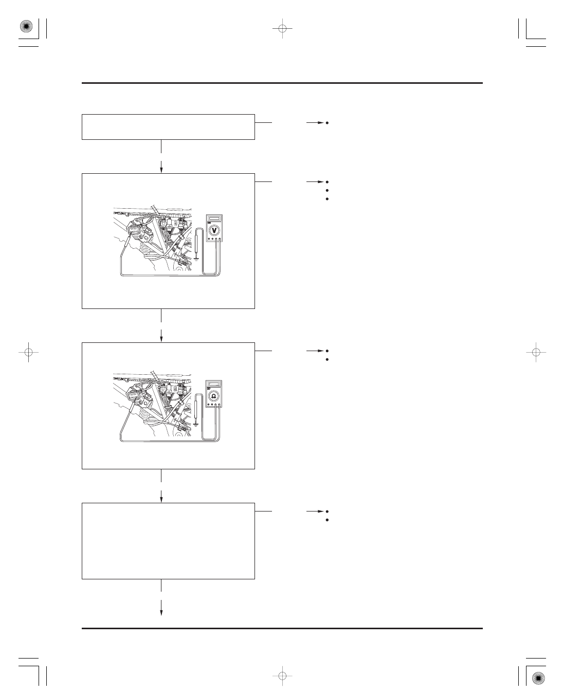
Problem Code 5: ECU Motor Driver Circuit

ELECTRIC SHIFT PROGRAM (ESP)

CONNECTION: Green (

)

Body ground (

)

STANDARD: Continuity

CONNECTIONS:

Orange (

)

Orange (

)

Green/Blue (

)

Green/Blue (

)

STANDARD: Continuity

CONNECTION: Red/Yellow (

)

Body ground

(

)

STANDARD: 11 V minimum

21-16

Check the connections of the ECU, motor and
related circuit.

Check for continuity between the Green terminal
and body ground.

Disconnect the ECU connector (5P/Brown).
Measure the voltage between the Red/Yellow
terminal and body ground.

Disconnect the motor connector (2P).
Check for continuity between the ECU connector
and motor connector.

Loose or poor contact of related circuits

Loose or poor contact of related circuits
Blown fuse
Open circuit in Red/Yellow wire

Loose or poor contact of related circuits
Open circuit in Green wire

Loose or poor contact of related circuits
Open or loose circuit in Orange and/or Green/
Blue wire

Normal

Abnormal

Abnormal

Abnormal

Normal

Normal

Normal

Abnormal

03/01/08 16:01:59 61HN400N_017

-------------------------------------------------------------------------------------------------------------------------------------------------------------

Problem Code 6: ECU Fail-Safe Circuit or
Problem Code 7: ECU Voltage Convert Circuit

ELECTRIC SHIFT PROGRAM (ESP)

21-17

Check the ES system failure (the gear indicator
blinks) when turning the ignition switch from
‘‘OFF’’ to ‘‘ON’’.

Check the ES system failure (the gear indicator
blinks) when turning the ignition switch from
‘‘OFF’’ to ‘‘ON’’.

Check the number of blinks (problem code
number)

Faulty motor

Replace the ECU with a new one and
troubleshoot again

No problem (temporary failure)

No problem (temporary failure)

Troubleshoot the problem code

Replace the ECU with a new one and
troubleshoot again

Connect a fully charged battery to the motor 2P
connector terminals.

Blinks

No blinks

Blinks

Six or seven blinks

No blinks

Does not

turn

Blinks other

than 6 or 7

times

Motor turns

03/01/08 16:02:07 61HN400N_018

-------------------------------------------------------------------------------------------------------------------------------------------------------------

+ −

Problem Code 10: Ignition Pulse Generator System

ELECTRIC SHIFT PROGRAM (ESP)

CONNECTION: Blue/Yellow (

)

Blue/Yellow

(

)

STANDARD: Continuity

21-18

Check the connection of the ECU, ignition pulse
generator and related circuit.

Check the connections of the ground cables.

Check the ignition system (page 18-4).

Loose or poor contact of related circuit

Loose or poor contact of ground cable(s)

Open circuit in Blue/Yellow wire
Loose or poor contact of related circuit

Ignition system failure

Replace the ECU with a new one and
troubleshoot again

No problem (temporary failure)

Check the number of gear indicator blinks while
driving in 1st gear over 6 km/h (4 mi/h) for more
than 6 seconds

Disconnect the ECU connector (22P/Brown) and
pulse generator connector (5P).
Check for continuity of the Blue/Yellow wire
between the ECU and pulse generator connector
terminals.

Normal

Abnormal

Abnormal

No continuity

Normal

Normal

Abnormal

Gear indicator

blinks

No blinks

Normal

03/01/08 16:02:15 61HN400N_019

-------------------------------------------------------------------------------------------------------------------------------------------------------------

+ −

+ −

CONNECTION
: Pink/Green (

)

Pink/Green (

)

: Black/Blue wire (

)

Black/Blue wire (

)

STANDARD: Continuity

Problem Code 11: Vehicle Speed Sensor System

ELECTRIC SHIFT PROGRAM (ESP)

21-19

Check the vehicle speed indicator during low
speed driving.

Check the combination meter (page 20-2)

Loose or poor contact of related terminals

Open circuit in Pink/Green wire

Replace the ECU with a new one and
troubleshoot again

No problem (temporary failure)

Check the number of gear indicator blinks while
driving in 1 st gear over 6 km/h (4 mi/h) for more
than 6 seconds.

Check the connection of the Pink/Green and Black
/Blue wires between the ECU and the vehicle
speed sensor.

Turn the ignition switch ‘‘OFF’’.
Disconnect the ECU connector (22P/Brown) and
speed sensor connector.
Check for continuity of both the Pink/Green wire
and the Black/Blue wire between the ECU
connector and vehicle speed sensor terminals.

Normal

Abnormal

Abnormal

Normal

Gear

indicator

blinks

No Continuity

Continuity

No blinks

03/01/08 16:02:23 61HN400N_020

-------------------------------------------------------------------------------------------------------------------------------------------------------------

SYSTEM INSPECTION

ELECTRIC SHIFT PROGRAM (ESP: TE/FE models)

ANGLE SENSOR

STANDARD:

STANDARD:

Clockwise turn:
Counterclockwise turn:

21-20

4

6 k

Compare the measurements to result of the fol-
lowing calculations.

2. Shift-up resistance:
Measure and record the resistance between the
Yellow/blue and Blue/green terminals while
upshifting the gear manually by using the gear
change tool.

3. Shift-down resistance:
Measure and record the resistance between the
Yellow/blue and Blue/green terminals while down-
shifting the gear in the same manner as at upshift.

Remove the angle sensor (page 21-21).
Check the sensor shaft hole and gearshift spindle
for wear or damage.
Check that the resistance between the Yellow/blue
and Blue/green wire terminals of the angle sensor
while turning the sensor shaft slowly.

If the measurement at the control unit is abnor-
mal and the one at the angle sensor is normal,
check for an open or short circuit, or loose or
poor sensor connector contact.
If the both measurements are abnormal, replace
the angle sensor.

1. Total resistance:
Turn the ignition switch to ‘‘OFF’’.
Disconnect the ECU 22P (gray: ’00

’02,

brown: After ’02) connector.
Measure and record the resistance between the
Black/red and Blue/green terminals of the harness
side control unit connector.

The angle sensor is normal if the result of the
calculations is less than 0.4 at upshift and more
than 0.6 at downshift.

If the measurement is abnormal, remove the angle
sensor cover (page 21-21) and disconnect the
sensor 3P connector and perform the same
inspection at the angle sensor terminals.

2

2

2

2

P

P

C

C

O

O

N

N

N

N

E

E

C

C

T

T

O

O

R

R

A

A

N

N

G

G

L

L

E

E

S

S

E

E

N

N

S

S

O

O

R

R

S

S

H

H

A

A

F

F

T

T

H

H

O

O

L

L

E

E

B

B

l

l

u

u

e

e

/

/

g

g

r

r

e

e

e

e

n

n

Y

Y

e

e

l

l

l

l

o

o

w

w

/

/

b

b

l

l

u

u

e

e

B

B

l

l

a

a

c

c

k

k

/

/

r

r

e

e

d

d

B

B

l

l

u

u

e

e

/

/

g

g

r

r

e

e

e

e

n

n

Y

Y

e

e

l

l

l

l

o

o

w

w

/

/

b

b

l

l

u

u

e

e

S

S

P

P

I

I

N

N

D

D

L

L

E

E

(20 °C/68 °F)

Shift-up resistance (step 2)/Total resistance (step 1)

0.4

Shift-down resistance (step 3)/Total resistance
(step 1)

0.6

Resistance decreases smoothly

Resistance increases

smoothly

Be caref ul not to

damage the sensor

shaf t hole.

03/01/08 16:02:37 61HN400N_021

-------------------------------------------------------------------------------------------------------------------------------------------------------------

REMOVAL

INSTALLATION

ELECTRIC SHIFT PROGRAM (ESP: TE/FE models)

STANDARD:

TORQUE:

21-21

Remove the two bolts and sensor cover.

Disconnect the 3P connector.
Remove the two socket bolts, washers and angle
sensor.

Install a new O-ring into the sensor groove.
Carefully install the angle sensor by aligning the
flat surfaces of the sensor shaft hole and gearshift
spindle end.
Apply locking agent to the socket bolt threads and
install the socket bolts with the washers and tighten
them.

6 N·m (0.6 kgf·m , 4.3 lbf·ft)

Install the sensor cover by aligning its groove with
the lug on the crankcase cover and tighten the two
bolts.

Connect the control unit 22P (gray: ’00

’02,

brown: After ’02) connector.
Measure the input voltage between the Black/red
(

) and Blue/green (

) terminals of the angle

sensor 3P connector with the ignition switch turned
to ‘‘ON’’.

4.7

5.3 V

If the input voltage is abnormal, or if there is no
input voltage, check for an open or short circuit in
the wire harness, or loose or poor connections in
the wire harness.

B

B

O

O

L

L

T

T

S

S

S

S

E

E

N

N

S

S

O

O

R

R

C

C

O

O

V

V

E

E

R

R

A

A

l

l

i

i

g

g

n

n

B

B

O

O

L

L

T

T

S

S

A

A

N

N

D

D

W

W

A

A

S

S

H

H

E

E

R

R

S

S

A

A

l

l

i

i

g

g

n

n

A

A

N

N

G

G

L

L

E

E

S

S

E

E

N

N

S

S

O

O

R

R

3

3

P

P

C

C

O

O

N

N

N

N

E

E

C

C

T

T

O

O

R

R

O

O

-

-

R

R

I

I

N

N

G

G

3

3

P

P

C

C

O

O

N

N

N

N

E

E

C

C

T

T

O

O

R

R

Route the control

motor wire prop-

erly 


( page 1-22).


03/01/08 16:02:50 61HN400N_022

-------------------------------------------------------------------------------------------------------------------------------------------------------------

MOTOR

ELECTRIC SHIFT PROGRAM (ESP: TE/FE models)

REMOVAL

CONTROL MOTOR AND REDUCTION

GEARS

21-22

Remove the sensor cover (page 21-21).

Remove the three wire bands from the fame down
tube and release the motor wire from the wire clip
on the frame cross member.

Disconnect the motor 2P (white) connector.

Remove the two mounting bolts and control motor.

REDUCTION GEARS

CONTROL MOTOR

O-RING

DOWEL PIN

O-RING

GEAR COVER

ANGLE SENSOR

SENSOR COVER

2

2

P

P

C

C

O

O

N

N

N

N

E

E

C

C

T

T

O

O

R

R

M

M

O

O

T

T

O

O

R

R

Replace the

control motor as

an assembly.

03/01/08 16:02:59 61HN400N_023

-------------------------------------------------------------------------------------------------------------------------------------------------------------


INSTALLATION

REMOVAL

INSTALLATION

SPECIFIED GREASE:

REDUCTION GEARS

ELECTRIC SHIFT PROGRAM (ESP: TE/FE models)

21-23

Remove the following:

Coat a new O-ring with engine oil and install it into
the groove in the crankcase cover.
Install the dowel pin.

Check the gear teeth for abnormal wear or damage.

Thoroughly clean the gears and journals.
Install the middle and upper gears into the
crankcase cover, and the lower gear by aligning its
wide groove (indicated by punch mark) with the
wide tooth on the shift spindle.
At this time, apply 3

5 g of specified grease to the

gear journals (both sides of the upper and middle
gears) and gear teeth as shown (encircled areas)
and install the gears.

Coat a new O-ring with engine oil and install it into
the groove in the motor.
Install the control motor and tighten the mounting
bolts.

Connect the motor 2P connector and secure the
motor and angle sensor wires with the wire clip
and wire bands.

Install the sensor cover (page 21-21).

angle sensor (page 21-21)
control motor (page 21-22)
gear cover

dowel pin
O-ring
reduction gears

Unirex N2 grease (ESSO) or
Unirex N3 grease (ESSO)

O

O

-

-

R

R

I

I

N

N

G

G

M

M

O

O

T

T

O

O

R

R

M

M

O

O

T

T

O

O

R

R

D

D

O

O

W

W

E

E

L

L

P

P

I

I

N

N

G

G

E

E

A

A

R

R

S

S

O

O

-

-

R

R

I

I

N

N

G

G

A

A

p

p

p

p

l

l

y

y

3

3

5

5

g

g

A

A

l

l

i

i

g

g

n

n

G

G

E

E

A

A

R

R

C

C

O

O

V

V

E

E

R

R

A

A

N

N

G

G

L

L

E

E

S

S

E

E

N

N

S

S

O

O

R

R

T he reduction

gears can be

serviced with the

engine installed in

the f rame.

Route the wires

properly ( page

1-22).

03/01/08 16:03:13 61HN400N_024

-------------------------------------------------------------------------------------------------------------------------------------------------------------


SYSTEM INSPECTION

ELECTRIC SHIFT PROGRAM (ESP: TE/FE models)

GEARSHIFT SWITCH

STANDARD:

21-24

Install the following:

gear cover
control motor (page 21-23)
angle sensor (page 21-21)

Disconnect the ECU 22P (gray) connector.
Check for continuity between the terminals of the
connector in each switch position.
Continuity should exist between the color coded
wires as follows:

If the continuity is abnormal, perform the same in-
spection at the handlebar switch 10P (green) con-
nector.
Remove the following connectors from the frame
and disconnect the 10P connector:

Connect the control unit 22P connector.
Measure the input voltage between the Black/red
(

) terminal of the harness side 10P (green) connec-

tor and ground (

) with the ignition switch turned

to ‘‘ON’’.

If the continuity at the control unit is abnormal
and the one at the 10P connector is normal, check
for an open or short circuit, or loose or poor con-
nector contact.
If both continuities are abnormal, replace the
gearshift switch.

ignition switch (4P white)
handlebar switch (10P green)

If the input voltage is abnormal, or if there is no
input voltage, check for an open or short circuit in
the wire harness, or loose or poor connections in
the wire harness.

4.7

5.3 V

Color

Position

Up

Free

Down

Black/

red

White/

Yellow

M

M

O

O

T

T

O

O

R

R

G

G

E

E

A

A

R

R

C

C

O

O

V

V

E

E

R

R

G

G

E

E

A

A

R

R

S

S

H

H

I

I

F

F

T

T

S

S

W

W

I

I

T

T

C

C

H

H

R

R

e

e

m

m

o

o

v

v

e

e

f

f

r

r

o

o

m

m

f

f

r

r

a

a

m

m

e

e

1

1

0

0

P

P

C

C

O

O

N

N

N

N

E

E

C

C

T

T

O

O

R

R

A

A

N

N

G

G

L

L

E

E

S

S

E

E

N

N

S

S

O

O

R

R

White/

blue

Black/

red

03/01/08 16:03:26 61HN400N_025

-------------------------------------------------------------------------------------------------------------------------------------------------------------

INSPECTION

REMOVAL/INSTALLATION

ELECTRIC SHIFT PROGRAM (ESP: TE/FE models)

REVERSE SHIFT SWITCH

TORQUE:

21-25

Disconnect the switch connector and remove the
reverse shift switch.

Install the switch with a new sealing washer and
tighten it.

Connect the switch connector securely.

13 N·m (1.3 kgf·m , 9 lbf·ft)

Remove the seat (page 2-4).

Remove the alternator 5P and gear position/reverse
shift switch 8P connectors from the frame.

Disconnect the gear position/reverse shift switch 8P
(white) connector and check for continuity between
the Gray/red terminal of the switch side connector
and ground.

There should be continuity with the reverse
selector operated and no continuity with it released.

R

R

e

e

m

m

o

o

v

v

e

e

f

f

r

r

o

o

m

m

f

f

r

r

a

a

m

m

e

e

8

8

P

P

C

C

O

O

N

N

N

N

E

E

C

C

T

T

O

O

R

R

S

S

R

R

E

E

V

V

E

E

R

R

S

S

E

E

S

S

H

H

I

I

F

F

T

T

S

S

W

W

I

I

T

T

C

C

H

H

A

A

N

N

D

D

W

W

A

A

S

S

H

H

E

E

R

R

C

C

O

O

N

N

N

N

E

E

C

C

T

T

O

O

R

R

03/01/08 16:03:35 61HN400N_026

-------------------------------------------------------------------------------------------------------------------------------------------------------------

MEMO

03/01/08 16:03:37 61HN400N_027

-------------------------------------------------------------------------------------------------------------------------------------------------------------

-------------------------------------------------------------------------------------------------------------------------------------------------------------


22-1 

WIRING DIAGRAMS

USA TM model

-------------------------------------------------------------------------------------------------------------------------------------------------------------


22-2 

WIRING DIAGRAMS

USA FM model

-------------------------------------------------------------------------------------------------------------------------------------------------------------


22-3 

WIRING DIAGRAMS

Canada TM/FM models

-------------------------------------------------------------------------------------------------------------------------------------------------------------

WIRING DIAGRAMS

USA TE/FE 00-02 models


22-4 

-------------------------------------------------------------------------------------------------------------------------------------------------------------


Content      ..     72      73      74      75     ..