ATV Honda TRX350 TM/TE, TRX350 FM/FE. Service Manual - part 72
LIGHTS/METERS/SWITCHES
20-0
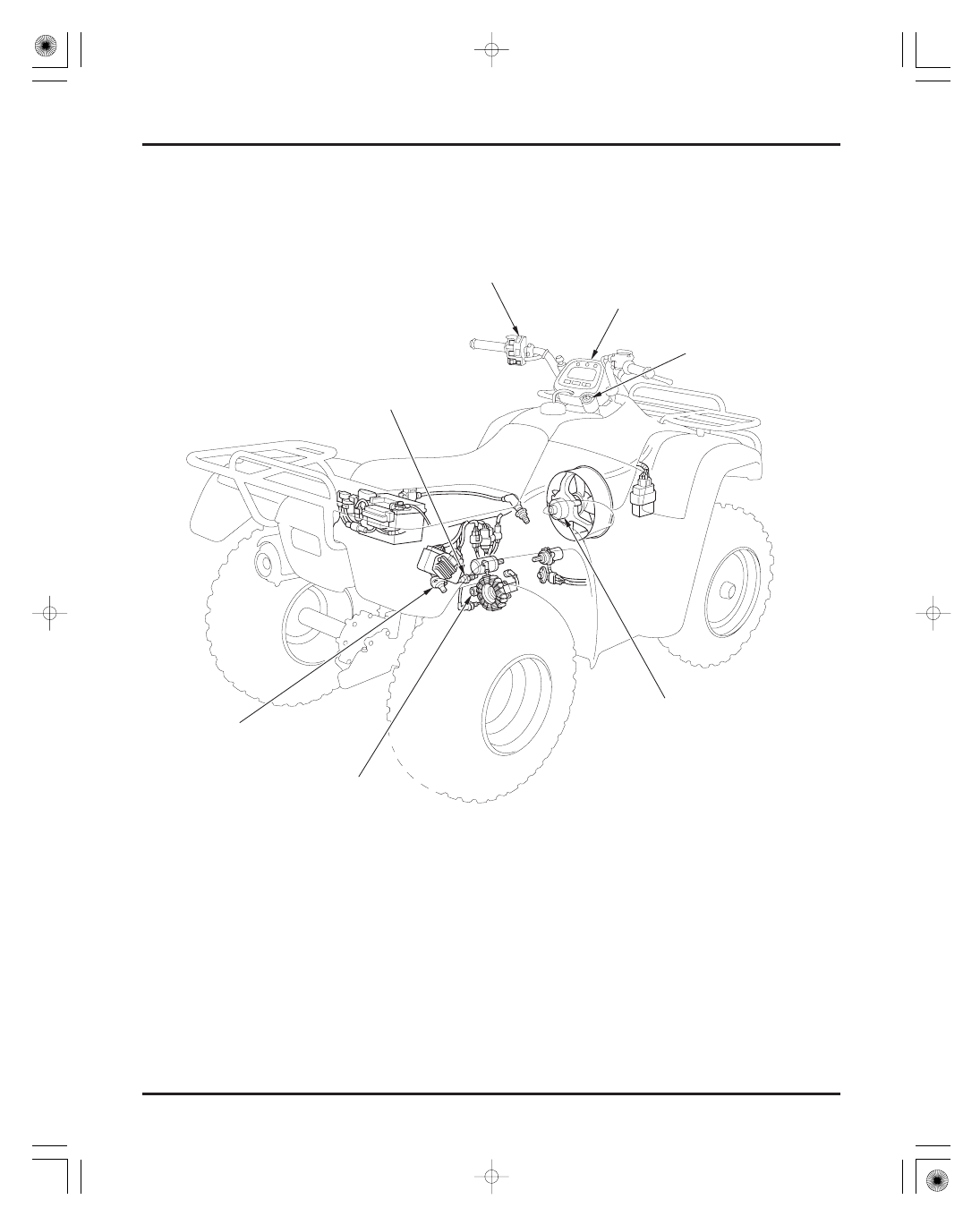
TE/FE model shown:
HANDLEBAR SWITCH
IGNITION SWITCH
GEAR POSITION SWITCH
OIL THERMOSENSOR
SPEED SENSOR
(U.S.A. TM/FM models-optional)
COOLING FAN MOTOR
(U.S.A. TM model-optional)
COMBINATION METER
(U.S.A. TM/FM models-optional)
03/01/08 15:55:30 61HN400M_001