Suzuki GSX-R1000. Service Manual - part 38
9A-9 Wiring Systems:
1
2
3
5
6
7
8
“C”
“D”
“E”
4
4
“A”
“B”
Upside
I947H1910909-03
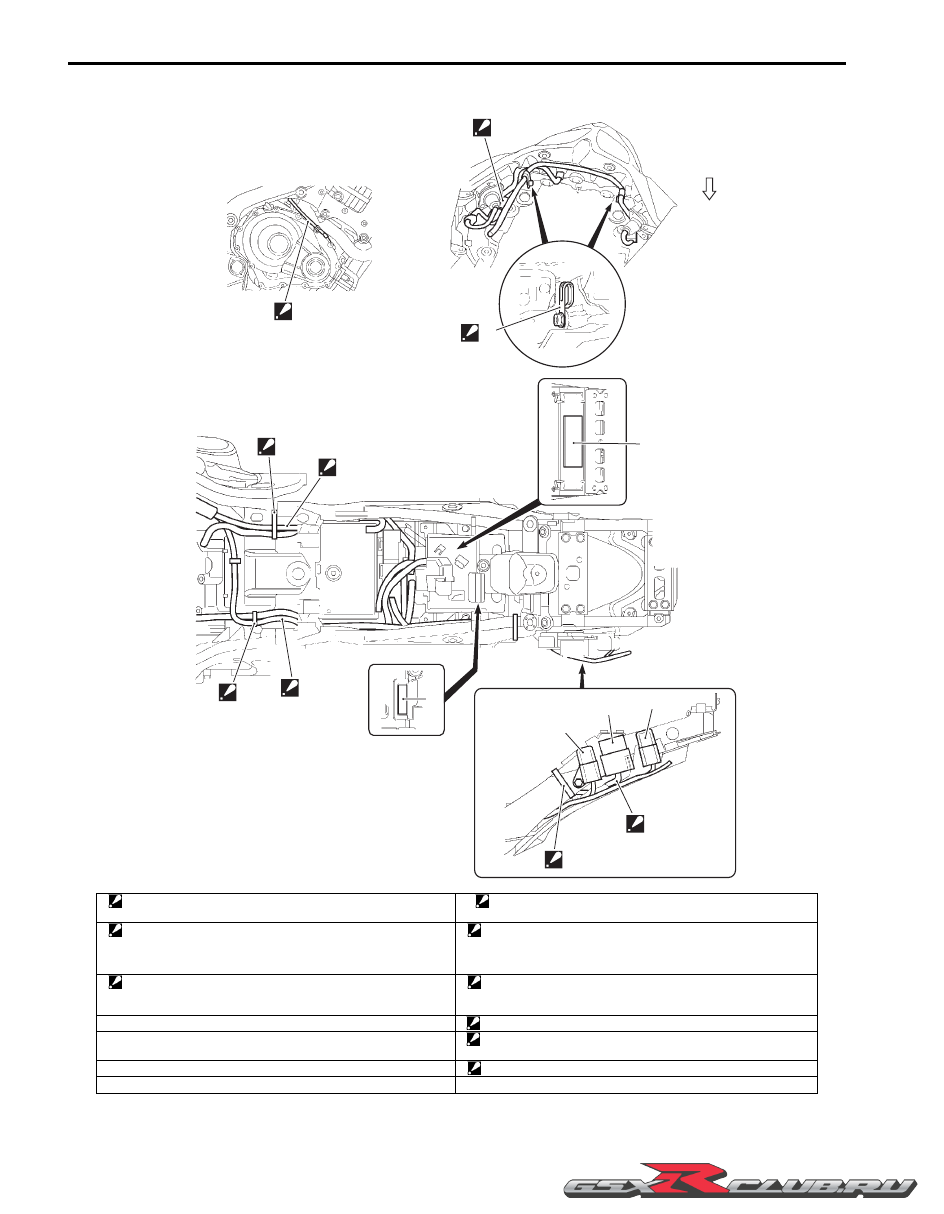
1. Steel clamp
: Set the clamp facing downward and bend it to outside.
8. Clamp
: Put the coupler in the frame rib and face the clamp end inside.
2. Clamp
: Bind the wiring harness and battery negative lead wires at blue
taping point and face the clamp end outside and downward. Be
sure not to slacken the rear brake light switch lead wire.
“A”: Be sure not to pinch the CKP sensor lead wire between engine
and water hose.
3. Clamp
: Bind the wiring harness and starter motor lead wire at blue taping
point and cut off the excess tip of the clamp.
“B”: Put the coupler between the rear turn signal and frame cover.
4. ECM cushion
“C”: Do not twist the wiring harness.
5. FP relay
“D”: Bring the part number sticker on the wiring harness upward.
Do not twist the wiring harness.
6. Turn signal/side-stand relay
“E”: Put the turn signal/side-stand relay lead wires inside the frame.
7. Cooling fan relay