Suzuki GSX-R1000. Service Manual - part 26
 

  Index      Manuals     Suzuki GSX-R1000. Service Manual


Search            copyright infringement  


Content      ..     24      25      26      27     ..


Suzuki GSX-R1000. Service Manual - part 26


1J-6 Charging System: 

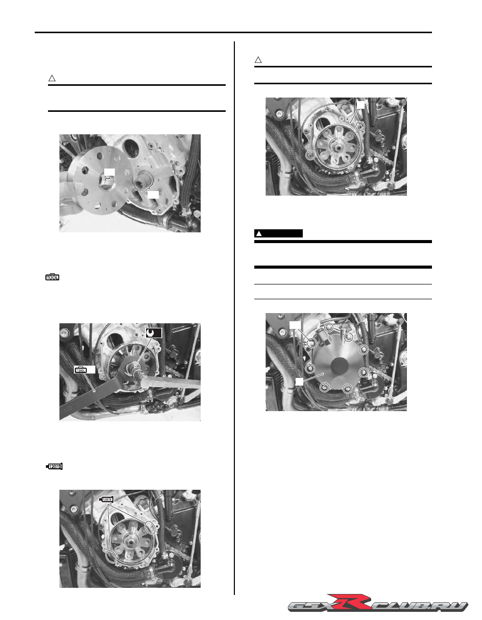
• Degrease the tapered portion “A” of generator rotor 

and also the crankshaft “B” with nonflammable 
cleaning solvent.

CAUTION

!


Dry these parts naturally. Do not wipe them 
with a cloth or use compressed air to dry.


• Install the generator rotor onto crankshaft.

• Hold the generator rotor with the special tool and 

tighten its bolt to the specified torque.

Special tool

(A):  09930–44530 (Rotor holder)

Tightening torque
Generator rotor bolt (c):  145 N·m (14.5 kgf-m, 
105.0 lbf-ft)

• Apply a bond lightly to the mating surfaces at the 

parting line between the upper and lower crankcases 
as shown.

:  Sealant 99000–31140 (SUZUKI BOND 

No.1207B or equivalent)

• Install the dowel pins and new gasket (2).

CAUTION

!


Use new gasket to prevent oil leakage.


• Install the generator cover (3) and tighten the 

generator cover bolts.

WARNING

!


Be careful not to pinch the finger between the 
generator cover and crankcase.


NOTE

Fit the clamp to the generator cover bolt “C”.


• Route the generator lead wire. Refer to “Wiring 

Harness Routing Diagram” in Section 9A (Page 9A-7).

“A”

“B”

I947H11A0023-01

(A)

(c)

I947H11A0012-02

I947H11A0013-01

2

I947H11A0014-01

3

“C”

I947H11A0015-01

-------------------------------------------------------------------------------------------------------------------------------------------------------------

Charging System:  1J-7

Regulator / Rectifier Construction

B947H11A06005

Regulator / Rectifier Removal and Installation

B947H11A06006

Removal

1) Turn the ignition switch OFF.

2) Remove the right side cowling. Refer to “Exterior 

Parts Removal and Installation” in Section 9D 
(Page 9D-6).

3) Lift and support the fuel tank. Refer to “Fuel Tank 

Removal and Installation” in Section 1G (Page 1G-
9)
.

4) Remove the EVAP system purge control solenoid 

valve bracket bolt. (E-33 only)

2

“A”

FWD

FWD

3

4

(a)

(a)

1

(a)

5

1

I947H11A0020-03

1. Regulator/rectifier

4. Spacer

: 10 N

m (1.0 kgf-m, 7.0 lbf-ft)

2. Regulator/rectifier bracket

5. Wiring harness

3. Air intake pipe (RH)

“A”: Connect the regulator/rectifier couplers under the wiring harness.

I947H11A0019-01

-------------------------------------------------------------------------------------------------------------------------------------------------------------

1J-8 Charging System: 

5) Disconnect the regulator/rectifier couplers (1).

6) Remove the regulator/rectifier as shown in the 

regulator/rectifier construction. Refer to “Regulator / 
Rectifier Construction” (Page 1J-7).

Installation

1) Install the regulator/rectifier as shown in the 

regulator/rectifier construction. Refer to “Regulator / 
Rectifier Construction” (Page 1J-7).

2) Reinstall the removed parts.

Regulator / Rectifier Inspection

B947H11A06007

Inspect the regulator/rectifier in the following procedures:

1) Turn the ignition switch OFF.

2) Disconnect the regulator/rectifier couplers. Refer to “Regulator / Rectifier Removal and Installation” (Page 1J-7).

3) Measure the voltage between the terminals using the multi-circuit testers as indicated in the following table. If the 

voltage is not within the specified value, replace the regulator/rectifier with a new one. Refer to “Regulator / 
Rectifier Removal and Installation” (Page 1J-7)
.

NOTE

If the tester reads 1.4 V and below when the tester probes are not connected, replace its battery.


Special tool

:  09900–25008 (Multi circuit tester set)

Tester knob indication
Diode test (

)

Unit: V

4) Connect the regulator/rectifier couplers and bind the clamp.

5) Reinstall the removed parts.

1

I947H11A0016-02

B

2

B

3

B

1

B/R

2

B/W

2

B/R

1

B/W

1

I823H11A0020-04

(+) probe of tester to:

B/R

1

B/R

2

B

1

B

2

B

3

B/W

1

B/W

2

(–) probe of 

tester to:

B/R

1

0

0.3 – 0.6

0.3 – 0.6

0.3 – 0.6

0.6 – 0.9

0.6 – 0.9

B/R

2

0

0.3 – 0.6

0.3 – 0.6

0.3 – 0.6

0.6 – 0.9

0.6 – 0.9

B

1

*

*

*

*

0.3 – 0.6

0.3 – 0.6

B

2

*

*

*

*

0.3 – 0.6

0.3 – 0.6

B

3

*

*

*

*

0.3 – 0.6

0.3 – 0.6

B/W

1

*

*

*

*

*

0

B/W

2

*

*

*

*

*

0

*1.4 V and more (tester’s battery voltage)

-------------------------------------------------------------------------------------------------------------------------------------------------------------

Charging System:  1J-9

Battery Components

B947H11A06008

Battery Charging

B947H11A06009

Initial Charging
Filling electrolyte

NOTE

When filling electrolyte, the battery must be 
removed from the vehicle and must be put on 
the level ground.


1) Remove the aluminum tape (1) which seals the 

battery filler holes “A”.

2) Remove the caps (2) from the electrolyte container.

NOTE

• Do not remove or pierce the sealed areas 

“B” of the electrolyte container.

• After filling the electrolyte completely, use 

the removed cap (2) as sealing caps of 
battery-filler holes.


3) Insert the nozzles of the electrolyte container (3) into 

the electrolyte filler holes of the battery.

4) Hold the electrolyte container firmly so that it does 

not fall.

NOTE

Do not allow any of the electrolyte to spill.


1. Anode plates

5. Stopper

2. Separator (Fiberglass plate)

6. Filter

3. Cathode plates

7. Terminal

4. Upper cover breather

8. Safety valve

1

3

2

4

5

6

7

8

I649G11A0046-03

1

“A”

I649G11A0039-03

2

“B”

I649G11A0040-03

3

I649G11A0041-03

-------------------------------------------------------------------------------------------------------------------------------------------------------------

1J-10 Charging System: 

5) Make sure that air bubbles (4) rise to the top of each 

electrolyte container, and leave in this position for 
about more than 20 minutes.

NOTE

If no air bubbles come out from a filler port, 
tap the bottom of the electrolyte container 
two or three times.
Never remove the container from the battery.


6) After confirming that the electrolyte has entered the 

battery completely, remove the electrolyte containers 
from the battery.

7) Wait for about 20 minutes.

8) Insert the caps (2) into the filler holes, pressing in 

firmly so that the top of the caps do not protrude 
above the upper surface of the battery’s top cover.

CAUTION

!


• Once the caps are installed to the battery, 

do not remove the caps.

• Do not tap the caps with a hammer when 

installing them.


Charging

For initial charging, use the charger specially designed 
for MF battery.

CAUTION

!


• For charging the battery, make sure to use 

the charger specially designed for MF 
battery. Otherwise, the battery may be 
overcharged resulting in shortened service 
life.

• Do not remove the cap during charging.

• Position the battery with the cap facing 

upward during charging.


4

I649G11A0042-03

I310G11A0024-01

2

I718H11A0027-01

Correct

Incorrect

I649G11A0047-02

-------------------------------------------------------------------------------------------------------------------------------------------------------------

Charging System:  1J-11

Battery Recharging

CAUTION

!


Do not remove the caps on the battery top 
while recharging.


NOTE

When the motorcycle is not used for a long 
period, check the battery every 1 month to 
prevent the battery discharge.


1) Remove the battery from the motorcycle. Refer to 

“Battery Removal and Installation” (Page 1J-11).

2) Measure the battery voltage using the multi-circuit 

tester.
If the voltage reading is less than the 12 V (DC), 
recharge the battery with a battery charger.

Recharging time
1.2 A for 5 to 10 hours or 5 A for 1 hour

CAUTION

!


Be careful not to permit the charging current 
to exceed 5 A at any time.


3) After recharging, wait at least 30 minutes and then 

measure the battery voltage using the multi-circuit 
tester.
If the battery voltage is less than 12.5 V, recharge 
the battery again.
If the battery voltage is still less than 12.5 V after 
recharging, replace the battery with a new one.

4) Install the battery to the motorcycle. Refer to “Battery 

Removal and Installation” (Page 1J-11).

Battery Removal and Installation

B947H11A06010

Removal

1) Remove the front seat. Refer to “Exterior Parts 

Removal and Installation” in Section 9D (Page 9D-
6)
.

2) Disconnect the battery (–) lead wire (1).

3) Disconnect the battery (+) lead wire (2).

NOTE

Be sure to disconnect the battery (–) lead 
wire (1) first, then disconnect the battery (+) 
lead wire (2).


4) Remove the battery (3) from the motorcycle.

“A”: Charging period

“B”: Stop charging

“A”

“B”

I649G11A0045-02

I705H11A0029-02

1

2

3

I947H11A0017-01

-------------------------------------------------------------------------------------------------------------------------------------------------------------

1J-12 Charging System: 

Installation

Install the battery in the reverse order of removal.
Pay attention to following points:

CAUTION

!


Never use anything except the specified 
battery.


• Tighten the battery lead wire bolts securely.

Battery Visual Inspection

B947H11A06011

Inspect the battery in the following procedures:

1) Remove the front seat. Refer to “Exterior Parts 

Removal and Installation” in Section 9D (Page 9D-
6).

2) Visually inspect the surface of the battery container.

If any signs of cracking or electrolyte leakage from 
the sides of the battery have occurred, replace the 
battery with a new one.
If the battery terminals are found to be coated with 
rust or an acidic white powdery substance, clean the 
battery terminals with sandpaper.

3) Install the front seat. Refer to “Exterior Parts 

Removal and Installation” in Section 9D (Page 9D-
6).

Specifications

Service Data

B947H11A07001

Electrical

Unit: mm

CAUTION

!


Never use anything except the specified battery.


Tightening Torque Specifications

B947H11A07002

NOTE

The specified tightening torque is described in the following.
“Regulator / Rectifier Construction” (Page 1J-7)


Reference:

For the tightening torque of fastener not specified in this section, refer to “Tightening Torque List” in Section 0C 
(Page 0C-9).

I947H11A0018-01

Item

Specification

Note

Generator coil resistance

0.12 – 0.6 

Generator maximum output

Approx. 375 W at 5 000 r/min

Generator no-load voltage (When 
engine is cold)

85 V (AC) and more at 5 000 r/min

Regulated voltage

14.0 – 15.5 V at 5 000 r/min

Battery

Type designation

FT12A-BS

Capacity

12 V 36.0 kC (10 Ah)/10 HR

Fastening part

Tightening torque

Note

N

m

kgf-m

lbf-ft

Generator stator set bolt

11

1.1 

8.0 

)

(Page 1J-5)

Generator lead wire set bolt

5.5

0.55 

4.0 

)

(Page 1J-5)

Generator rotor bolt

145

14.5 

105.0 

)

(Page 1J-6)

-------------------------------------------------------------------------------------------------------------------------------------------------------------

Charging System:  1J-13

Special Tools and Equipment

Recommended Service Material

B947H11A08001

Special Tool

B947H11A08002

Material

SUZUKI recommended product or Specification

Note

Sealant

SUZUKI BOND No.1207B or 
equivalent

P/No.: 99000–31140

)

(Page 1J-5) / 

)

(Page 1J-

6)

09900–25008

09930–30460

Multi circuit tester set

Rotor remover bolt

)

(Page 1J-3) / 

)

(Page 1J-

3) / 

)

(Page 1J-4) / 

)

(Page 1J-4) / 

)

(Page 1J-

8)

)

(Page 1J-5)

09930–34970

09930–44530

Rotor remover

Rotor holder

)

(Page 1J-5)

)

(Page 1J-5) / 

)

(Page 1J-

6)

-------------------------------------------------------------------------------------------------------------------------------------------------------------

1K-1 Exhaust System: 

Engine

Exhaust System

Precautions

Precautions for Exhaust System

B947H11B00001

WARNING

!


To avoid the risk of being burned, do not touch the exhaust system when the system is hot. Any 
service on the exhaust system should be performed when the system is cool.


CAUTION

!


Make sure that the exhaust pipes and muffler have enough clearance from the rubber parts and plastic 
parts to avoid melting.


General Description

Exhaust Control System Description

B947H11B01001

The exhaust control system (EXCS) consists of the exhaust control valve (EXCV), exhaust control valve actuator 
(EXCVA) and exhaust control valve cables (EXCV cables). 
EXCV is installed in the exhaust pipe. EXCVA is mounted inside of the right frame. The EXCV is operated by the 
EXCVA via the cables. This system is designed to improve the engine torque at low engine rpm.

1

2

I947H11B0001-01

1. Exhaust control valve actuator (EXCVA)

2. Exhaust control valve (EXCV)

-------------------------------------------------------------------------------------------------------------------------------------------------------------

Exhaust System:  1K-2

Exhaust Control System Operation

B947H11B01002

The EXCS is operated by the signal supplied from the ECM. The open/close operation of the EXCV is performed by 
the EXCVA which is controlled by the ECM by changing the current direction of the actuator motor. The position 
sensor (incorporated in the EXCVA) detects the EXCVA movement by measuring the voltage and then the ECM 
determines the EXCV opening angle based on the engine rpm and gear positions. Every time the ignition switch is 
turned ON, the EXCVA automatically drives the EXCV and detects full close/open position voltages and sets the 
EXCV to middle position.

FULL CLOSE

I947H11B0002-01

-------------------------------------------------------------------------------------------------------------------------------------------------------------

1K-3 Exhaust System: 

FULL OPEN

I947H11B0003-01

-------------------------------------------------------------------------------------------------------------------------------------------------------------

Exhaust System:  1K-4

Repair Instructions

Exhaust Control System Construction

B947H11B06001

1

2

1

2

“ a ”

“ b ”

“ c ”

(a)

“A”

I947H11B0004-02

1. EXCV cable No. 1 (CL)

: 5 N

m (0.5 kgf-m, 3.5 lbf-ft)

“c”: 11 – 12 mm (0.43 – 0.47 in)

2. EXCV cable No. 2 (OP)

“a”: 42 – 43 mm (1.65 – 1.69 in)

“A”: When loosening or tightening the pulley bolt, be sure to fix the 

pulley with an adjustable wrench, or EXCVA may get damaged.

“b”: 60 – 61 mm (2.36 – 2.40 in)

-------------------------------------------------------------------------------------------------------------------------------------------------------------

1K-5 Exhaust System: 

Exhaust System Components

B947H11B06002

CAUTION

!


Replace the gaskets and connectors with new ones when reassembling.


(b)

(b)

(b)

(b)

1

2

3

5

6

6

7

8

4

“A”

(a)

(a)

(a)

(a)

(a)

(a)

(f)

(c)

(d)

(e)

4

4

(c)

I947H11B0005-03

1. Exhaust pipe gasket

7. EXCV cable No. 1

: 5.5 N

m (0.55 kgf-m, 4.0 lbf-ft)

2. Exhaust pipe assembly

8. EXCV cable No. 2

: 5 N

m (0.5 kgf-m, 3.5 lbf-ft)

3. HO2 sensor

“A”: When loosening or tightening the pulley bolt, be sure to fix the 

pulley with an adjustable wrench, or EXCVA may get damaged.

: 30  N

m (3.0 kgf-m, 21.5 lbf-ft)

4. Connector

: Install the connector so that the 
chamfer side faces backward.

: 23 N

m (2.3 kgf-m, 16.5 lbf-ft)

: Apply muffler seal.

5. Muffler chamber

: 25 N

m (2.5 kgf-m, 18.0 lbf-ft)

: Do not reuse.

6. Muffler body

: 10 N

m (1.0 kgf-m, 7.0 lbf-ft)

-------------------------------------------------------------------------------------------------------------------------------------------------------------

Exhaust System:  1K-6

EXCV Cable Removal and Installation

B947H11B06003

Removal

1) Turn the ignition switch OFF.

2) Remove the front seat. Refer to “Exterior Parts 

Removal and Installation” in Section 9D (Page 9D-
6)
.

3) Remove the left side cowling. Refer to “Exterior 

Parts Removal and Installation” in Section 9D 
(Page 9D-6).

4) Connect the special tool (Mode select switch) to the 

dealer mode coupler. Refer to “Self-Diagnostic 
Procedures” in Section 1A (Page 1A-12).

5) After turning the mode select switch ON, turn the 

ignition switch ON.

Special tool

(A):  09930–82720 (Mode selection switch)

6) Check that the cable slots of the EXCVA pulley 

comes to the middle (Adjustment position) “A”.

7) Turn the ignition switch OFF.

CAUTION

!


Before removing the EXCV cables, be sure to 
set the EXCVA pulley to the adjustment 
position.


8) Loosen the lock-nut (1) on the No. 2 cable (2) and 

turn in the cable adjuster (3) fully.

9) Loosen the lock-nut (4) on the No. 1 cable (5) and 

turn in the cable adjuster (6) fully.

10) Disconnect the No. 2 cable (2) and No. 1 cable (5) 

from the EXCVA pulley (7).

11) Loosen the lock-nuts.

12) Disconnect the No. 2 cable (2) and No. 1 cable (5) 

from the EXCV pulley (8).

(A)

I947H11B0006-01

“A”

I947H11B0007-01

1

2

3

5

6

4

I947H11B0008-01

2

5

7

I947H11B0009-02

2

5

8

I947H11B0010-02

-------------------------------------------------------------------------------------------------------------------------------------------------------------

1K-7 Exhaust System: 

Installation

CAUTION

!


The cable slots of EXCVA pulley must be 
located adjustment position.


1) Temporarily connect the EXCV cable No. 1 

(47H0CL) (1) and No. 2 (47H0OP) (2) to the exhaust 
pipe and EXCV pulley.

NOTE

The EXCV cables are identified by the letters.
No. 1 cable (1): 47H0CL
No. 2 cable (2): 47H0OP


2) Tighten the lock-nuts (3) on the No. 1 cable.

3) Adjust the inner cable length “a” of No. 1 cable in 42 

– 43 mm (1.65 – 1.69 in) by turning the adjuster (4), 
then tighten the lock-nuts (5).

4) Turn in the adjuster (6) on the No. 2 cable fully.

5) Turn the No. 2 cable adjuster (7) in or out until the 

inner cable length “b” becomes 60 – 61 mm (2.36 – 
2.40 in).
After adjusting the inner cable length “b”, tighten the 
lock-nuts (8).

6) Connect the other end of EXCV cable No. 1 (1) and 

No. 2 (2) to the EXCVA pulley (9).

7) After connecting the No. 2 cable (2), loosen the lock-

nut (10) and turn the adjuster (6) in or out until 11 – 
12 mm (0.43 – 0.47 in) of the thread length “c” on the 
cable adjuster can be provided and tighten the lock-
nut (10).

8) Inspect the EXCVA position sensor output voltage. 

Refer to “EXCVA Adjustment” (Page 1K-9).

EXCVA Removal and Installation

B947H11B06004

Removal

1) Turn the ignition switch OFF.

2) Remove the left side cowling. Refer to “Exterior 

Parts Removal and Installation” in Section 9D 
(Page 9D-6)
.

3) Connect the special tool (Mode select switch) to the 

dealer mode coupler. Refer to “Self-Diagnostic 
Procedures” in Section 1A (Page 1A-12).

“ a ”

“ b ”

1

2

3

5

6

7

8

4

I947H11B0011-02

1

2

9

I947H11B0012-01

2

6

10

“ c ”

I947H11B0013-01

-------------------------------------------------------------------------------------------------------------------------------------------------------------

Exhaust System:  1K-8

4) After turning the mode select switch ON, turn the 

ignition switch ON.

Special tool

(A):  09930–82720 (Mode selection switch)

5) Check that the cable slots of the EXCVA pulley 

comes to the middle (Adjustment position) “A”.

6) Turn the ignition switch OFF.

CAUTION

!


Before removing the EXCVA, be sure to set 
the EXCVA pulley to the adjustment position.


7) Disconnect the EXCVA coupler (1).

8) Remove the EXCV cables (2). Refer to “EXCV Cable 

Removal and Installation” (Page 1K-6).

9) Remove the EXCVA (3) with the bracket.

10) Remove the bracket from the EXCVA.

11) Hold the pulley with an adjustable wrench, and 

loosen the pulley mounting bolt (4).

CAUTION

!


• When loosening or tightening the pulley 

bolt, be sure to fix the pulley with an 
adjustable wrench, or EXCVA may get 
damaged.

• Do not use the adjustable wrench to turn 

EXCVA pulley so as not to cause damage 
to the internal gear of EXCVA.


12) Remove the pulley from the EXCVA body.

(A)

I947H11B0014-01

“A”

I947H11B0015-01

1

I947H11B0016-01

3

2

I947H11B0017-01

I947H11B0037-01

4

I947H11B0038-01

-------------------------------------------------------------------------------------------------------------------------------------------------------------


Content      ..     24      25      26      27     ..