Suzuki GSX-R1000. Service Manual - part 24


  Index      Manuals     Suzuki GSX-R1000. Service Manual


Search            copyright infringement  


Content      ..     22      23      24      25     ..


Suzuki GSX-R1000. Service Manual - part 24


1H-1 Ignition System: 

Engine

Ignition System

General Description

Immobilizer Description (For E-02, 19, 24, 51)

B947H11801001

The immobilizer, an anti-theft system, is installed as a 
standard equipment.
The immobilizer verifies that the key ID agrees with ECM 
ID by means of radio communication through the 
immobilizer antenna. When the ID agreement is verified, 
the system makes the engine ready to start.

Operation

When the ignition switch is turned ON with the engine 
stop switch in ON, the immobi-antenna and ECM are 
powered ON. 
The ECM transmits a signal to the transponder through 
the immobi-antenna in order to make comparison 
between the key ID and ECM ID. 
With the signal received, the transponder transmits the 
key ID signal to ECM so that ECM can make comparison 
with its own ID, and if it matches, the engine is made 
ready to start.

Also, when the ignition switch is turned ON, the indicator 
light flashes as many as the number of IDs registered in 
ECM. Thereafter, if the IDs are in agreement, the 
indicator light turns on for two seconds to notify of 
completion in successful communication.
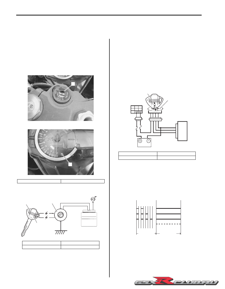
If the indicator light (LED) flashes fast, it notifies of 
communication error or disagreement of ID.

1. Immobilizer antenna

2. Indicator light

1. Immobilizer antenna

3. Transponder

2. Indicator light

4. ID

1

I947H1180001-01

2

I947H1180002-01

ECM

1

2

3

4

I815H1180002-02

1. Immobilizer antenna

3. Ignition switch

2. Transponder

4. ECM

OFF

ON

R

O

1

2

3

4

I815H1180003-01

Flashing

Lighting

2 registered

3 registered

4 registered

Normal

Normal

Normal

Abnormal

Fast flashing

Approx. 1.6 sec.

Approx. 2.0 sec.

I705H1180006-01

-------------------------------------------------------------------------------------------------------------------------------------------------------------

Ignition System:  1H-2

NOTE

If the indicator light flashes fast, turn the 
ignition switch OFF then ON to make 
judgment again as there is possible 
misjudgment due to environmental radio 
interference.


CAUTION

!


When the battery performance is lowered in 
winter (low temperature), the system may at 
times makes a re-judgment at the time of 
beginning the starter motor operation. In this 
case, the indicator light operation starts 
immediately after the starter operation.


Drive Mode Selector Description

B947H11801002

Engine power characteristics can be changed in 3 
modes by operating the drive mode selector to meet 
various riding conditions and rider’s preference.

Operation

Drive mode is preset at A-mode when the ignition switch 
and engine stop switch are turned on. Follow the 
procedure below to operate drive mode selector.

1) Turn on the ignition switch and engine stop switch.

2) Push the drive mode selector UP

or DOWN 

for 1 second until the drive mode indicator 

shows A.

3) Push the drive mode selector to change drive mode. 

Pushing the UP

switch can change from A to C 

to B to A. Pushing the DOWN

switch can change 

from A to B to C to A. The drive mode indicator 
indicates actual drive mode.

NOTE

• Operating the drive mode selector while 

riding with the throttle opened will change 
the engine speed because of engine power 
characteristics change.

• Drive mode indicator blinks when drive 

mode change operation is failed.

• Turning off the ignition switch or engine 

stop switch will return the drive mode to A-
mode. Start the engine and reset the drive 
mode.


Drive Mode
A-mode

A-mode provides sharp throttle response at all throttle 
opening range to obtain maximum engine power.

B-mode

B-mode provides softer throttle response than A-mode 
up to middle throttle opening range.

C-mode

C-mode provides soft throttle response at all throttle 
opening range by reducing engine power.

5. Indicator light

5

I947H1180003-01

I947H1180015-01

A

B

A, B

C

Engine power

Throttle opening

I838H1180001-01

-------------------------------------------------------------------------------------------------------------------------------------------------------------

1H-3 Ignition System: 

Schematic and Routing Diagram

Ignition System Diagram

B947H11802001

Refer to “Wire Color Symbols” in Section 0A (Page 0A-5).

Ignition System Components Location

B947H11802002

Refer to “Electrical Components Location” in Section 0A (Page 0A-7).

#1

#2

#3

#4

CKP 
sensor

TP
sensor

ECT
sensor

GP
switch

Engine stop switch

Side-stand
relay

Fuse

Fuse

Ignition
switch

Battery

ECM

I947H1180004-01

-------------------------------------------------------------------------------------------------------------------------------------------------------------

Ignition System:  1H-4

Diagnostic Information and Procedures

Ignition System Symptom Diagnosis

B947H11804001

Condition

Possible cause

Correction / Reference Item

Spark plug not sparking

Damaged spark plug.

Replace.

Fouled spark plugs.

Clean or replace.

Wet spark plugs.

Clean and dry or replace.

Defective ignition coil.

Replace.

Defective CKP sensor.

Replace.

Defective ECM.

Replace.

Open-circuited wiring connections.

Repair or replace.

Engine stalls easily (No 
spark)

Fouled spark plugs.

Clean or replace.

Defective CKP sensor.

Replace.

Defective ECM.

Replace.

Spark plug is wet or 
quickly becomes fouled 
with carbon

Excessively rich air/fuel mixture.

Inspect FI system.

Excessively high idling speed.

Inspect FI system.

Incorrect gasoline.

Change.

Dirty air cleaner element.

Clean or replace.

Incorrect spark plug (Cold type).

Change to hot type spark plug.

Spark plug quickly 
becomes fouled with oil 
or carbon

Worn piston rings.

Replace.

Worn pistons.

Replace.

Worn cylinders.

Replace.

Excessive valve-stem to valve-guide 
clearance.

Replace.

Worn valve stem oil seals.

Replace.

Spark plug electrodes 
overheat or burn

Incorrect spark plug (Hot type).

Change to cold type spark plug.

Overheated engine.

Tune-up.

Loose spark plugs.

Tighten.

Excessively lean air/fuel mixture.

Inspect FI system.

-------------------------------------------------------------------------------------------------------------------------------------------------------------

1H-5 Ignition System: 

No Spark or Poor Spark

B947H11804002

Troubleshooting

NOTE

Check that the transmission is in neutral and the engine stop switch is in the “RUN” position. Grasp 
the clutch lever. Check that the fuse is not blown and the battery is fully-charged before diagnosing.


Step

Action

Yes

No

1

Check the ignition system couplers for poor connections.

Is there connection in the ignition system couplers?

Go to Step 2.

Poor connection of 
couplers.

2

Measure the battery voltage between input lead wires at the 
ECM with the ignition switch in the “ON” position. (E-02, 19, 
24, 51: O/G and B/W, E-03, 14, 28, 33: O/W and B/W)

Is the voltage OK?

Go to Step 3.

• Faulty ignition switch.

• Faulty turn signal/

side-stand relay.

• Faulty engine stop 

switch.

• Broken wire harness 

or poor connection of 
related circuit 
couplers.

3

Measure the ignition coil primary peak voltage. Refer to 
“Ignition Coil Inspection” (Page 1H-7).

NOTE

This inspection method is applicable only with 
the multi-circuit tester and the peak volt adaptor.


Is the peak voltage OK?

Go to Step 4.

Go to Step 5.

4

Inspect the spark plugs. Refer to “Spark Plug Inspection and 
Cleaning” in Section 0B (Page 0B-9).

Is the spark plug(-s) OK?

Go to Step 5.

Faulty spark plug(-s).

5

Inspect the ignition coil. Refer to “Ignition Coil Inspection” 
(Page 1H-7).

Is the ignition coil OK?

Go to Step 6.

• Faulty ignition coil.

• Poor connection of 

the ignition coil.

6

Measure the CKP sensor peak voltage and its resistance. 
Refer to “CKP Sensor Inspection” (Page 1H-9).

NOTE

The CKP sensor peak voltage inspection is 
applicable only with the multi-circuit tester and 
peak volt adaptor.


Are the peak voltage and resistance OK?

• Faulty  ECM.

• Open or short circuit 

in wire harness.

• Poor connection of 

ignition couplers.

• Faulty CKP sensor.

• Metal particles or 

foreign material being 
stuck on the CKP 
sensor and rotor tip.

-------------------------------------------------------------------------------------------------------------------------------------------------------------

Ignition System:  1H-6

Repair Instructions

Ignition Coil and Spark Plug Removal and 
Installation

B947H11806001

Removal

WARNING

!


The hot engine can burn you.
Wait until the engine is cool enough to touch.


1) Turn the ignition switch OFF.

2) Remove the air cleaner box. Refer to “Air Cleaner 

Box Removal and Installation” in Section 1D 
(Page 1D-7).

3) Disconnect the lead wire couplers (1).

CAUTION

!


Disconnect the lead wire coupler before 
removing the ignition coil to avoid lead wire 
coupler damage.


4) Remove the ignition coils (2).

CAUTION

!


• Do not pry up the ignition coil with a 

screwdriver or a bar to avoid its damage.

• Be careful not to drop the ignition coil to 

prevent short/open circuit.


5) Remove the spark plugs with the spark plug wrench.

Special tool

(A):  09930–10121 (Spark plug wrench set)

Installation

Install the spark plugs in the reverse order of removal. 
Pay attention to the following points:

• Screw the spark plugs into the cylinder head with 

fingers, and then tighten them to the specified torque.

CAUTION

!


Do not cross thread or over tighten the spark 
plug, or such an operation will damage the 
aluminum threads of the cylinder head.


Special tool

(A):  09930–10121 (Spark plug wrench set)

Tightening torque
Spark plug:  11 N·m (1.1 kgf-m, 8.0 lbf-ft)

1

I947H1180005-03

2

I947H1180006-02

(A)

I947H1180007-03

(A)

I947H1180008-03

-------------------------------------------------------------------------------------------------------------------------------------------------------------

1H-7 Ignition System: 

• Install the ignition coil and connect their lead wire 

couplers.

CAUTION

!


Do not hit the ignition coil with a plastic 
hammer when installing it.


Spark Plug Inspection and Cleaning

B947H11806002

Refer to “Spark Plug Inspection and Cleaning” in Section 
0B (Page 0B-9).

Ignition Coil Inspection

B947H11806003

Refer to “Electrical Components Location” in Section 0A 
(Page 0A-7).

Ignition Coil Primary Peak Voltage

1) Remove the air cleaner box. Refer to “Air Cleaner 

Box Removal and Installation” in Section 1D 
(Page 1D-7).

2) Disconnect all ignition coil. Refer to “Ignition Coil and 

Spark Plug Removal and Installation” (Page 1H-6).

3) Connect the new spark plugs to each ignition coil.

4) Connect all the ignition coil lead wire couplers to the 

ignition coil respectively, and ground them on the 
cylinder head (each spark plug hole).

CAUTION

!


Avoid grounding the spark plugs and 
suppling the electrical shock to the cylinder 
head cover (magnesium parts) to prevent the 
magnesium material from damage.


NOTE

Be sure that all the spark plugs are 
connected properly and the battery used is in 
fully-charged condition.


INCORRECT

I718H1180012-01

I947H1180009-03

1. New spark plug

“A”: Contact the spark plug to the cylinder head.

I947H1180010-03

1

“A”

I823H1180011-02

-------------------------------------------------------------------------------------------------------------------------------------------------------------

Ignition System:  1H-8

5) Insert the needle pointed probe to the lead wire 

coupler.

CAUTION

!


Use the special tool to prevent the rubber of 
the water proof coupler from damage.


6) Connect the multi-circuit tester with the peak voltage 

adaptor as follows.

CAUTION

!


Before using the multi-circuit tester and peak 
voltage adaptor, refer to the appropriate 
instruction manual.


Special tool

(A):  09900–25008 (Multi circuit tester set)
(B):  09900–25009 (Needle-point probe set)

Tester knob indication: Voltage (

)

7) Measure the ignition coil primary peak voltage in the 

following procedures:

WARNING

!


Do not touch the tester probes and spark 
plugs to prevent an electric shock while 
testing.


a) Shift the transmission into neutral, turn the 

ignition switch ON and grasp the clutch lever.

b) Press the starter button and allow the engine to 

crank for a few seconds, and then measure the 
ignition coil primary peak voltage.

8) Repeat the b) procedure several times and measure 

the highest peak voltage.
If the voltage is lower than standard range, inspect 
the ignition coil and the CKP sensor.

Ignition coil primary peak voltage
80 V and more

9) After measuring the ignition coil primary peak 

voltage, reinstall the removed parts.

(+) Probe

(–) Probe

Ignition coil #1

W/Bl wire terminal

Ground

Ignition coil #2

Black wire terminal

Ground

Ignition coil #3

Yellow wire terminal

Ground

Ignition coil #4

Green wire terminal

Ground

(B)

(A)

I718H1180003-02

2. ECM

“B”: (+) probe

3. Peak voltage adaptor

“C”: (–) probe

4. New spark plug

“D”: To engine stop switch

5. Ignition coil

2

3

“B”

“C”

“D”

5

4

I823H1180026-01

-------------------------------------------------------------------------------------------------------------------------------------------------------------

1H-9 Ignition System: 

Ignition Coil Resistance

1) Remove the ignition coil. Refer to “Ignition Coil and 

Spark Plug Removal and Installation” (Page 1H-6).

2) Measure the ignition coil for resistance in both 

primary and secondary coils. If the resistance is not 
within the standard range, replace the ignition coil 
with a new one.

Special tool

(A):  09900–25008 (Multi circuit tester set)

Tester knob indication
Resistance (

)

Ignition coil resistance
Primary: 1.1 – 1.9 

 ((+) terminal – (–) terminal)

Secondary: 6.4 – 9.6 k

 (Spark plug cap – (–) 

terminal)

3) After measuring the ignition coil resistance, reinstall 

the removed parts.

CKP Sensor Inspection

B947H11806004

Refer to “Electrical Components Location” in Section 0A 
(Page 0A-7).

CKP Sensor Peak Voltage

1) Lift and support the fuel tank. Refer to “Fuel Tank 

Removal and Installation” in Section 1G (Page 1G-
9).

2) Disconnect the CKP sensor coupler (1).

NOTE

Be sure that all of the couplers are connected 
properly and the battery is fully-charged.


3) Connect the multi-circuit tester with the peak volt 

adaptor as follows.

CAUTION

!


Before using the multi-circuit tester and peak 
voltage adaptor, refer to the appropriate 
instruction manual.


Special tool

(A):  09900–25008 (Multi circuit tester set)

Tester knob indication: Voltage (

)

4) Measure the CKP sensor peak voltage in the 

following procedures:

a) Shift the transmission into neutral, turn the 

ignition switch ON and grasp the clutch lever.

b) Press the starter button and allow the engine to 

crank for a few seconds, and then measure the 
CKP sensor peak voltage.

5) Repeat the b) procedure several times and measure 

the highest CKP sensor peak voltage.

CKP sensor peak voltage
0.5 V and more (B – Bl/Y)

(A)

I718H1180005-01

(

ޓ

)

(

ޓ

)

(

ޓ

)

(

ޓ

)

I718H1180006-01

CKP sensor

(+) Probe

(–) Probe

B

Bl/Y

1. CKP sensor coupler

3. Peak voltage adaptor

2. CKP sensor

1

I947H1180011-02

Bl/Y

B

Bl/Y

B

(A)

1

2

3

I947H1180020-01

-------------------------------------------------------------------------------------------------------------------------------------------------------------

Ignition System:  1H-10

6) If the peak voltage is within the specification, check 

the continuity between the CKP sensor coupler and 
ECM coupler.

CAUTION

!


Normally, use the needle pointed probe to the 
backside of the lead wire coupler to prevent 
the terminal bend and terminal alignment.


7) After measuring the CKP sensor peak voltage, 

connect the CKP sensor coupler.

CKP Sensor Resistance

1) Lift and support the fuel tank. Refer to “Fuel Tank 

Removal and Installation” in Section 1G (Page 1G-
9)
.

2) Disconnect the CKP sensor coupler (1).

3) Measure the resistance between the lead wires and 

ground. If the resistance is not within the standard 
range, replace the CKP sensor with a new one. 
Refer to “CKP Sensor Removal and Installation” 
(Page 1H-10).

Tester knob indication
Resistance (

)

CKP sensor resistance
142 – 194 

 (B – Bl/Y)


 (B – Ground)

4) After measuring the CKP sensor resistance, connect 

the CKP sensor coupler.

5) Reinstall the fuel tank. Refer to “Fuel Tank Removal 

and Installation” in Section 1G (Page 1G-9).

CKP Sensor Removal and Installation

B947H11806005

Refer to “Generator Removal and Installation” in Section 
1J (Page 1J-4).

Engine Stop Switch Inspection

B947H11806006

Inspect the engine stop switch in the following 
procedures:

1) Turn the ignition switch OFF.

2) Remove the air cleaner box. Refer to “Air Cleaner 

Box Removal and Installation” in Section 1D 
(Page 1D-7)
.

3) Disconnect the right handlebar switch coupler (1).

4) Inspect the engine stop switch for continuity with a 

tester.
If any abnormality is found, replace the right 
handlebar switch assembly with a new one. Refer to 
“Handlebar Removal and Installation” in Section 6B 
(Page 6B-2).

Special tool

:  09900–25008 (Multi circuit tester set)

Tester knob indication
Continuity (

)

5) After finishing the engine stop switch inspection, 

reinstall the removed parts.

Ignition Switch Inspection

B947H11806007

Refer to “Ignition Switch Inspection” in Section 9C 
(Page 9C-7).

1. CKP sensor coupler

2. CKP sensor

1

I947H1180012-02

1

2

I837H1180011-01

1

I947H1180013-01

O/B

O/W

Color

Position

OFF

RUN

(

)

(

)

I815H1180012-01

-------------------------------------------------------------------------------------------------------------------------------------------------------------

1H-11 Ignition System: 

Ignition Switch Removal and Installation

B947H11806008

Removal

1) Remove the air cleaner box. Refer to “Air Cleaner 

Box Removal and Installation” in Section 1D 
(Page 1D-7).

2) Disconnect the ignition switch lead wire coupler (1).

3) Disconnect the immobilizer lead wire coupler (2). 

(For E-02, 19, 24, 51)

4) Remove the harness clamp (3).

5) Remove the ignition switch (4) with the special tools.

Special tool

(A):  09930–11920 (Torx bit (JT40H))
(B):  09930–11940 (Torx bit holder)

Installation

Install the ignition switch in the reverse order of removal. 
Pay attention to the following points:

• Tighten the ignition switch mounting bolts (1), right 

and left with the special tools.

CAUTION

!


When reusing the ignition switch bolts, clean 
the threaded part and apply a thread lock to 
them.


Special tool

(A):  09930–11920 (Torx bit (JT40H))
(B):  09930–11940 (Torx bit holder)

:  Thread lock cement 99000–32110 

(THREAD LOCK CEMENT SUPER “1322” or 
equivalent)

2

1

I947H1180014-01

3

I947H1180016-01

(A)

(B)

4

I947H1180017-01

(A)

(B)

1

I947H1180018-01

-------------------------------------------------------------------------------------------------------------------------------------------------------------

Ignition System:  1H-12

Drive Mode Selector Inspection

B947H11806009

Inspect the drive mode selector in the following procedures:

1) Set up the SDS tool. (Refer to the SDS operation manual for further details.)

2) Turn the ignition switch ON.

3) Click “Data monitor”.

4) Make sure each of “Driving mode selection” on the monitor is indicated “Open”.

5) Push each of drive mode selector (1) and (2). At this time, if the indication is changed to “GND”, the function is 

normal.

I947H1180021-01

1

2

I947H1180019-02

-------------------------------------------------------------------------------------------------------------------------------------------------------------

1H-13 Ignition System: 

Specifications

Service Data

B947H11807001

Electrical

Unit: mm (in)

Tightening Torque Specifications

B947H11807002

Reference:

For the tightening torque of fastener not specified in this section, refer to “Tightening Torque List” in Section 0C 
(Page 0C-9).

Item

Specification

Note

Firing order

 2 

 4 

 3

Spark plug

Type

NGK: CR9EIA-9

DENSO: IU27D

Gap

0.8 – 0.9 (0.031 – 0.035)

Spark performance

Over 8 (0.3) at 1 atm.

CKP sensor resistance

142 – 194 

CKP sensor peak voltage

0.5 V and more

When cranking

Ignition coil resistance

Primary

1.1 – 1.9 

Terminal – 

Terminal

Secondary

6.4 – 9.6 k

Plug cap – 

Terminal

Ignition coil primary peak voltage

80 V and more

When cranking

Fastening part

Tightening torque

Note

N

m

kgf-m

lbf-ft

Spark plug

11

1.1 

8.0 

)

(Page 1H-6)

-------------------------------------------------------------------------------------------------------------------------------------------------------------

Ignition System:  1H-14

Special Tools and Equipment

Recommended Service Material

B947H11808001

Special Tool

B947H11808002

Material

SUZUKI recommended product or Specification

Note

Thread lock cement

THREAD LOCK CEMENT SUPER 
“1322” or equivalent

P/No.: 99000–32110

)

(Page 1H-11)

09900–25008

09900–25009

Multi circuit tester set

Needle-point probe set

)

(Page 1H-8) / 

)

(Page 1H-

9) / 

)

(Page 1H-9) / 

)

(Page 1H-10)

)

(Page 1H-8)

09930–10121

09930–11920

Spark plug wrench set

Torx bit (JT40H)

)

(Page 1H-6) / 

)

(Page 1H-

6)

)

(Page 1H-11) / 

)

(Page 1H-11)

09930–11940
Torx bit holder

)

(Page 1H-11) / 

)

(Page 1H-11)

-------------------------------------------------------------------------------------------------------------------------------------------------------------

1I-1 Starting System: 

Engine

Starting System

Schematic and Routing Diagram

Starting System Diagram

B947H11902001

Refer to “Wire Color Symbols” in Section 0A (Page 0A-5).

Component Location

Starting System Components Location

B947H11903001

Refer to “Electrical Components Location” in Section 0A (Page 0A-7).

Diagnostic Information and Procedures

Starting System Symptom Diagnosis

B947H11904001

O/B

Y/G

Bl

G

O

R

Starter 

motor


Ignition

switch

Fuse (30 A)

Side-stand

switch

Starter relay

Engine stop

switch

Starter

button

Turn signal/

side-stand relay

Fuse

Gear

position

switch

Batter

y

Clutch lever

position switch

B/W

B/Y

O/W

To
ignition coil

I837H1190038-01

Condition

Possible cause

Correction / Reference Item

Engine does not turn 
though the starter motor 
runs

Faulty starter clutch.

Replace.

Starter button is not 
effective

Run down battery.

Repair or replace.

Defective switch contacts.

Replace.

Brushes not seating properly on starter 
motor commutator.

Repair or replace.

Defective starter relay or starter interlock 
switch.

Replace.

Defective main fuse.

Replace.

-------------------------------------------------------------------------------------------------------------------------------------------------------------

Starting System:  1I-2

Starter Motor Will Not Run

B947H11904002

NOTE

Make sure the fuses are not blown and the battery is fully-charged before diagnosing.


Troubleshooting

Starter Motor Runs But Does Not Crank The Engine

B947H11904003

The starter motor runs when the transmission is in neutral, but does not run when the transmission is in any position 
other than neutral, with the side-stand up.

Step

Action

Yes

No

1

1) Shift the transmission into neutral.

2) Grasp the clutch lever, turn on the ignition switch with 

the engine stop switch in the “RUN” position and listen 
for a click from the starter relay when the starter button is 
pushed.

Is the click sound heard?

Go to Step 2.

Go to Step 3.

2

Check if the starter motor runs when its terminal is 
connected to the battery (+) terminal. (Do not use thin “wire” 
because a large amount of current flows.)

Does the starter motor run?

• Faulty starter relay.

• Loose or 

disconnected starter 
motor lead wire.

• Loose or 

disconnected 
between starter relay 
and battery (+) 
terminal.

Faulty starter motor.

3

Measure the starter relay voltage at the starter relay terminal 
(between Y/G (+) and B/Y (–)) when the starter button is 
pushed.

Is the voltage OK?

Go to Step 4.

• Faulty ignition switch.

• Faulty engine stop 

switch.

• Faulty clutch lever 

position switch.

• Faulty gear position 

switch.

• Faulty turn signal/

side-stand relay.

• Faulty starter button.

• Faulty side-stand 

switch.

• Poor contact of the 

coupler.

• Open circuit in wire 

harness.

4

Check the starter relay. Refer to “Starter Relay Inspection” 
(Page 1I-6).

Is the starter relay OK?

Poor contact of the 
starter relay.

Faulty starter relay.

Step

Action

Yes

No

1

Check the side-stand switch. Refer to “Side-stand / Ignition 
Interlock System Parts Inspection” (Page 1I-7).

Is the side-stand switch OK?

Go to Step 2.

Faulty side-stand 
switch.

2

Check the starter clutch. Refer to “Starter Clutch Removal 
and Installation” (Page 1I-10).

Is the starter clutch OK?

• Open circuit in wire 

harness.

• Poor contact of 

connector.

Faulty starter clutch.

-------------------------------------------------------------------------------------------------------------------------------------------------------------


Content      ..     22      23      24      25     ..