Suzuki GSX-R1000. Service Manual - part 8
1A-50 Engine General Information and Diagnosis:
DTC “C15” (P0115-H/L): ECT Sensor Circuit Malfunction
B947H11104014
Detected Condition and Possible Cause
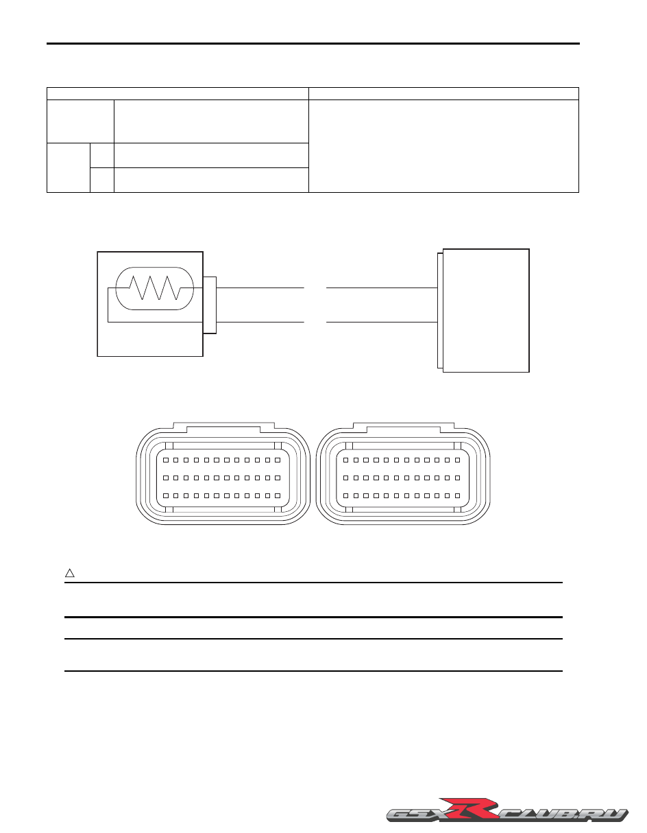
Wiring Diagram
ECM coupler (Harness side)
Troubleshooting
CAUTION
!
When using the multi-circuit tester, do not strongly touch the terminal of the ECM coupler with a
needle pointed tester probe to prevent terminal damage.
NOTE
After repairing the trouble, clear the DTC using SDS tool. Refer to “Use of SDS Diagnosis Reset
Procedures” (Page 1A-14).
Detected Condition
Possible Cause
C15
Output voltage is not with in the following
range.
0.15 V
≤
Sensor voltage < 4.85 V
• ECT sensor circuit open or short.
• ECT sensor malfunction.
• ECM malfunction.
P0115
H
Sensor voltage is higher than specified
value.
• ECT sensor circuit is open or ground circuit open.
L
Sensor voltage is lower than specified
value.
• ECT sensor circuit shorted to ground.
ECM
E2
ECTS
B/Br
ECT sensor
B/BI
32
35
I837H1110027-01
1
2
3
4
5
6
7
8
9 10 11 12
13 14 15 16 17 18 19 20 21 22 23 24
25 26 27 28 29 30 31 32 33 34 35 36
37 38 39 40 41 42 43 44 45 46 47 48
49 50 51 52 53 54 55 56 57 58 59 60
61 62 63 64 65 66 67 68 69 70 71 72
I837H1110007-02