CFMoto ATV CF500/CF500-A. Service Manual - part 12


  Index      Manuals     CFMoto ATV CF500/CF500-A. Service Manual


Search            copyright infringement  


Content      ..     10      11      12      13     ..


CFMoto ATV CF500/CF500-A. Service Manual - part 12


                                                                            15. Engine Removal, Inspection & Installation 

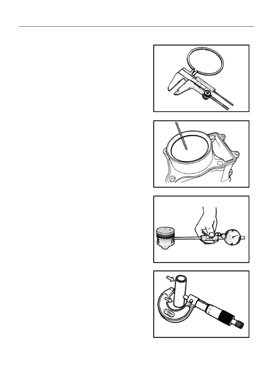
Piston Ring Free End Gap and End Gap 

z

  Before installing piston rings, use vernier caliper to 

measure the free end gap of each ring, and then fit 
ring into the cylinder. 

z

  Use thickness gauge to measure each ring end gap, 

if any ring has an excess end gap, replace the 
piston ring. 


Piston ring free end gap limit:   
Top ring: 8.9mm 
2

nd

 ring: 9.5mm 

 
Piston ring end gap limit: 
Top Ring: 0.60mm 
2

nd

 ring: 0.60mm 

 
Tool: Vernier caliper 

Thickness gauge 


Piston Pin and Pin Bore 

z

  Use a bore gauge to measure the inner diameter of 

piston pin bore. 

z

  Use micrometer to measure outer diameter of piston 

pin. 

z

  If out of limit, replace both piston and piston pin. 

 
Piston pin bore limit: 23.030mm 


z

  Use micrometer to measure piston pin outer 

diameter at three points   


Piston pin outer diameter limit: 22.980mm 
Tools: Bore gauge (18-35mm) 

Micrometer (0-25mm) 


15-26 

                                                                            15. Engine Removal, Inspection & Installation 

Connecting Rod/Crankshaft 
Connecting rod small end I.D. 

z

  Use a dial gauge to measure the I.D. of connecting 

rod small end. If the measurement exceeds the limit, 
replace the connecting rod. 

 
Connecting rod small end I.D. : 23.040mm 
Tool: Dial Gauge (18-35mm) 


Connecting Rod Deflection 

z

  Check the movement of the small end of the rod and 

inspect the wear of the small end. This method is 
also applicable to check and inspection of big end. 


Connecting Rod Deflection: 3.0mm 
Tools: Dial Gauge 

Magnetic stand 
V-block 

 
Connecting Rod Big End Side Clearance 

z

  Push the big end to one side, and use thickness 

gauge to measure the other side clearance. 

z

  If out of limit, replace with a new crankshaft. 


Connecting Rod big end side clearance: 1.0mm 
Tool: Thickness Gauge 


Crankshaft Run-out 

z

  Support crankshaft with “V” blocks as illustrated. Put 

the dial gauge, slowly turn the crankshaft and 
measure run-out with a dial gauge. 

z

  If the run-out exceeds the limit, correct or replace 

the crankshaft. 


Run out limit: 0.08mm 
Tools: dial gauge 

Magnetic stand 
V-block 


 15-27 

                                                                            15. Engine Removal, Inspection & Installation 

Clutch 
Clutch Shoes 

z

  Check clutch for chipping, scrape, uneven wear or 

heat discoloration. At the same time check depth of 
the grooves of clutch shoes. If any of the clutch 
shoes has no groove, replace the clutch. 


Note:

 clutch should be replaced as a set. 


Clutch Wheel   

Check the inner clutch wheel 

 for scratches, scuffs or 

blue discoloration or uneven wear. If any damage is 
found, replace the clutch wheel with a new one. 

z

  Check oil seal lip for wear or damage.   

Wear or Damage: 

Replace 

z

  Use special tool to remove oil seal 

Tool: Oil seal remover 

z

  Use special tool to assemble oil seal 

Tool: Oil seal installer set 

z

  Check the turning of bearing.   

Abnormal damage: 

Replace             


Assembly 


z

  Apply lubricant grease to oil seal when assembling.   


15-28 


                                                                            15. Engine Removal, Inspection & Installation 

Primary and Secondary Sheave 


15-29

                                                                            15. Engine Removal, Inspection & Installation 

Primary Sliding Sheave 
 
 
Disassembly 

z

 Remove 

spacer 

z

 Remove 

Cam 

and Roller


Roller 

z

  Check each roller and sliding face for wear and 

damage. 

Wear and damage: 

Replace 


Note: 

rollers should be replaced as a set. 


Oil Seal 

z

  Check oil seal lip for wear and damage. 

Wear and damage: 

Replace 


z

  Remove the oil seal 


 15-30 

                                                                            15. Engine Removal, Inspection & Installation 

Primary Sliding Sheave and Fixed Sheave 

z

  Check the drive face for any abnormal conditions 

such as damage or stepped wearing. 

Damage or wearing: 

 Replace 


z

  Install oil seal with special tool. 

Tool: Bearing install set 


Tool   Tool  


Assembly 

Reverse the removal procedure of primary sliding and 
fixed sheave for installation. 
 
Pay attention to the following:   
 

z

  Apply grease to inner bore and oil seal lip. 


Note: 

z

  Wipe off any excessive grease thoroughly. 

z

  Take care not to attach any lubricant grease 

to contact surface of drive belt. 

Material: Lubricant grease 


z

  Position 8 rollers 

on the primary sliding sheave 

z


Install 4 dampers 

 to cam 


z

  Install cam to primary sliding sheave. 


Notes: 

When inserting the spacer, press down the cam 
so that the rollers will not come out of position. 


15-31 

                                                                            15. Engine Removal, Inspection & Installation 

Install spacer 
 
Secondary Sheave 
Disassembly 

z

  Use special tool and holder to hold the secondary 

sheave. Remove secondary sheave nut with special 
tool. 


Caution:  

Do not remove the ring nut before attaching the 
clutch spring compressor.   

 
Tool: Nut Wrench 
     Sheave Holder 


z

  Attach special tool to the secondary sliding sheave 

and compress it by turning in the tool handle. 


Note: 

Make sure that spring end A is inserted into slot 
B of the tool handle. 


z

  Remove ring nut. 

Tool: Secondary sliding sheave spring compressor 


Note: 

Since a high spring force applies to the 
secondary sliding sheave, take special care that 
the secondary sliding sheave will not come off 
abruptly. 


z

  Slowly loosen tool handle and remove the special 

tool. 

tool


 15-32 

                                                                            15. Engine Removal, Inspection & Installation 


z

 Remove 

spring 


z

  Remove spring seat  .


z

  Remove guide pin and spacer. 


z

  Remove secondary sliding sheave   


O-ring and Oil Seal 

 
Check the O-ring and oil seal for wear and damage. 

O-ring    oil seal 

Wear and Damage: 

 Replace 


z

  Remove Oil Seal 


 15-33 

                                                                            15. Engine Removal, Inspection & Installation 

z

  Install oil seal with special tool. 

Tool: Bearing install set 


tool  tool  


Secondary Sheave Spring 

z

  Use vernier caliper to check the spring free length. If 

the length is shorter than the service limit, replace 
with a new one. 

Service Limit: 145.4mm


lubricant grease 


Secondary Sliding and Fixed Sheave 

z

  Check drive face for any abnormal condition such 

as stepped wear or damage. 

Wear or damage: 

 Replace 


Lubricant grease 


Assembly 

z

  Install a new O-ring 

z

  Apply lubricant grease to O-ring, oil seal lip and 

guide pin groove. 

Material: lubricant grease 


 15-34 

                                                                            15. Engine Removal, Inspection & Installation 

z

  Install guide pin and spacer 


Note: 

To avoid damage to the oil seal lip during 

assembly, slide the lip with a 0.1mm steel sheet 
as guide. 


z

  Install spring seat. Align hole A with hole B. 


z

  Install spring and spring plate. Insert spring end into 

the hole. 


z

  Compress spring with special tool. 

z

  Align the secondary sheave end with spring plate 

hole. 

Tool: Secondary sheave spring compressor 


tool 


z

  Tighten ring nut temporarily. 

tool


z

  Remove the special tool from secondary sheave.   


  15-35 

                                                                            15. Engine Removal, Inspection & Installation 

z

  Tighten the ring nut with special tool to the specified 

torque. 


Ring Nut Tightening Torque: 100N·m 
Tool: Ring nut wrench 

Sheave Holder 


Drive belt 


z

  Check belt for any greasy substance. 

z

  Check contact surface of belt for any cracks and 

damage. 

z

  Check belt width with vernier caliper. 


Damage, width out of range: 

Replace 


Belt width service limit: 33.5mm 
Tool: vernier caliper 


Caution:  

If belt surface is stained with grease or oil, degrease the 
belt thoroughly.   


15-36 

                                                                            15. Engine Removal, Inspection & Installation 

Transmission 


No. Description 

Qty 

No. Description 

Qty. 

MAIN SHAFT. GEARSHIFT   

10 

DRIVEN GEAR,    HIGH RANGE 

SHIFT CAM 

11 

DRIVEN GEAR, LOW RANGE   

RIGHT CRANKCASE 

12 

SPRING, SHIFT FORK 

LEFT CRANKCASE 

13 

RIGHT SHIFT FORK 

DRIVEN SECTOR GEAR 

14 

GUIDE BAR 

SPROCKET, REVERSE GEAR   

15 

DRIVEN SHAFT 

CHAIN, REVERSE GEAR 

16 

SPRING, SHIFT FORK 

DRIVEN OUTPUT GEAR 

17 

LEFT SHIFT FORK 

DRIVE SECTOR GEAR 


18 SHIFT 

FORK 

ASSEMBLY 


   15-37

                                                                            15. Engine Removal, Inspection & Installation 

Inspection 

z

  Check main shaft gear and sprocket surface for any 

damage or over wear. 

Damage or over wear: 

 Replace 


z

  Check reverse gear chain for any damage or over 

wear. 

Damage or over wear: 

 Replace 


z

  Disassemble driven shaft as illustrated. 


z

  Check each gear surface for any damage or over 

wear. 

z

  Check bearing and collar for any wear or damage.. 

Damage or over wear: 

 Replace 


    15-38

                                                                            15. Engine Removal, Inspection & Installation 

z

  Check the shift fork clearance with a thickness 

gauge in the groove of its gear. 

Clearance exceeds the limit: 

 Replace 


Shift fork to Groove clearance 
Standard clearance :0.10-0.30mm 
Service Limit :0. 50mm 


z

  Measure shift fork groove width with vernier caliper 


Standard shift fork groove width: 6.05-6.15mm 


z

  Measure shift fork thickness with vernier calipers; 


Standard fork thickness: 5.08-5.90mm 


z

  Check shift fork   and   for damage 

or bend   


Damage, bend: 

 Replace 


z

  Install shift fork to guide bar and move left and right. 

In case of any unsmooth moving, replace with a new 
one. 


15-39 

                                                                            15. Engine Removal, Inspection & Installation 

z

  Put the guide bar on a flat plate and roll it. In case of 

any bend, replace with a new one. 


NOTE

:DON NOT attempt to correct a bent guide bar.


z

  Check shift fork spring for breakage, damage 

Broken or damaged: 

 Replace 


z

  Check shift cam groove for scratches, damage. 

Scratch or damage: 

 Replace 


Assembly 

 
Reverse the removal procedure for assembly. Pay   
attention to the following: 
 

z

  Use new retainers. Pay attention to the direction of 

the retainers. Fit to the side where the thrust is as 
illustrated. 


z

  Coat the gears and shafts with engine oil before 

assembly. 


Note: 

z

  Do not reuse the retainers 

z

  Do not expand of the gap end of new retainers too 

wide when assembling. 

z

  Make sure that all the retainers are properly fitted. 


    15-40       

                                                                            15. Engine Removal, Inspection & Installation 

z

  When assembling the guide bar, take care not to 

assemble the two shift forks and springs in the 
opposite direction. 

 
1. Guide bar             2. Retainer 
3. Left shift fork           4. Shift fork Spring (small) 
5. Right shift fork         6. shift fork spring (big) 
7. Spring seat 


OIL PUMP 

z

  Disassembly oil pump as illustrated: 

1. Oil pump housing    2.Dowel pin 
3.Oil pump shaft       4.Straight pin 
5.Inner rotor, oil pump    6.Outer rotor, oil pump 
7. Oil pump cover 


z

  Check oil pump housing and cover for cracks and 

damage. 

Crack or damage: 

 Replace 


z

  Measure top clearance “a” between inner and outer 

rotors and side clearance “b” between outer rotor 
and oil pump housing. If the clearance exceeds the 
limit, replace with new one. 


Top Clearance:0. 03-0.10mm 
Service Limit: 0. 15mm 
 
 
Side clearance: 0. 03-0.10mm 
Service Limit: 0.12mm        


15-41 


Content      ..     10      11      12      13     ..