CFMoto ATV CF500/CF500-A. Service Manual - part 10
14. Checks & Adjustment
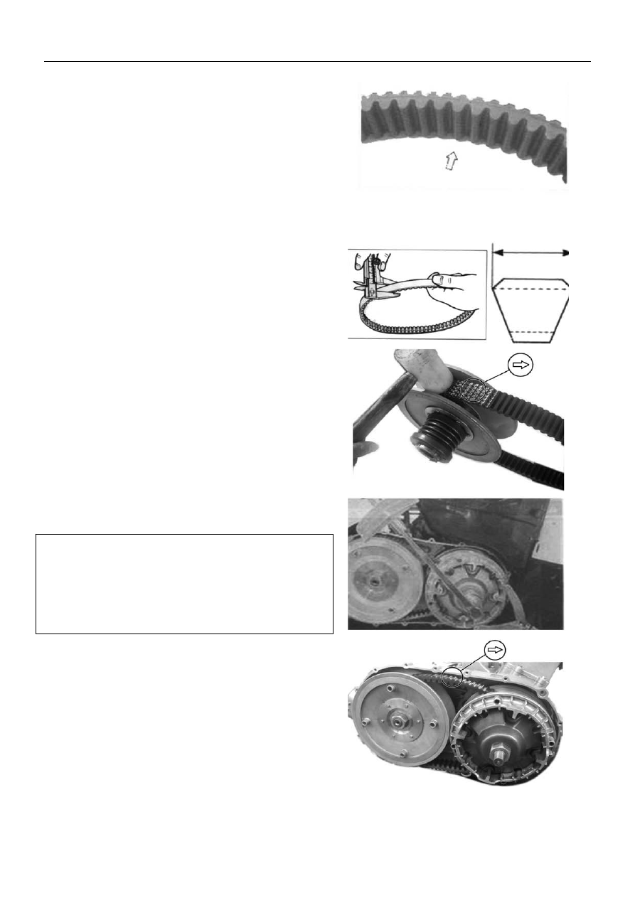
Inspection:
Inspect drive belt for wear and damage. If any cracks or
damages are found, replace drive belt with a new one.
Inspect drive belt for width, if width is out of
service limit,
replace drive belt with a new one.
Service Limit: 33.5mm
Tool: Vernier Caliper
Installation
Reverse the removal procedure for installation. Pay
attention to the following:
Insert drive belt, as low as possible, between secondary
sliding sheave and primary fixed sheave.
Hold secondary sheave with a special tool and tighten
the nut to the specified torque.
Nut, Secondary Sheave: 115 N.m
Install primary sheave and nut. Hold the primary sheave
with a special tool and tighten the nut to the specified
torque.
Nut, Primary Sheave:115N.m
Turn primary sheave, until the drive belt is properly
seated and both the primary and secondary sheaves
rotate together smoothly and without slipping.
Caution:
z
Fit the drive belt with the arrow on the drive belt
points toward normal turning direction.
z
The drive belt contact surface of the driven face
should be thoroughly cleaned.
Install CVT cover
14-7