CFMoto ATV CF500-5B, CF500-5C. Service Manual - part 2
1
-
16
C
F
MOTO
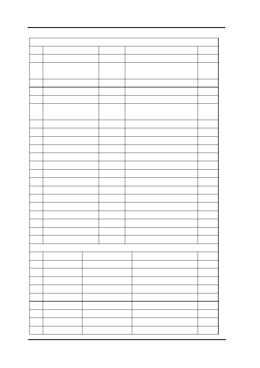
Engine Tools
Measuring Tools
No
Name
Type
Function
Remark
1
Vernier Calipers
0-150mm
Measure length and thickness
2
Micrometers
0-25mm
Measure the outer diameters of swing
arm, valve rod and camshaft
3
Dial gauge
25-50mm
Measure max. lift range of camshaft
4
Dial gauge
75-100mm
Measure piston skirt
5
Inner dia. Gauge, Cylinder
Measure inner dia. of cylinder head
6
Inner dia. Gauge,
10-34mm
Inner dia. of swing arm, piston pin hole,
and rod head hole
7
Dial Test Indicator
1/100
Run-out
8
Knife Straight Edge
plainness
9
Feeler Gauge
Plainness, adjusting valve clearance
10
Fuel Level Gauge
Fuel level length of carburetor
11
Plastic gauge
Fit clearance
12
pull tension gauge
Spring bounce
13
Tachometer
Engine rotation rate
14
Cylinder Pressure Meter
pressure in cyclinder
15
Oil Pressure Gage
Oil pressure
16
Barometer
Opening pressure of radiator cover
17
Ohmmeter
Resistance and voltage
18
Amperemeter
Opening of currency / switch
19
Thermometer
Liquid temperature
20
Timing Lights
Test spark timing
21
Torque Tester
One Set
Tightening torque
Auxiliary Measuring Instrument
22
Alcohol Burner
Warming up
23
Magnet Stand
Install dialgauge
24
Slab
Auxiliary measure supplementary
25
V-Block
Run-out supplementary
26
Forcep
Install valve clip
27
Plier
Disassemble and install circlip
28
Joint Plier
Disassemble and install flange
29
Impact Driver
Disassemble cross recessed bolt
30
Slot Type Driver
31
Cross Type Driver