CFMoto ATV Terralander CF800-2. Service Manual - part 6
14 FRONT DIFFERENTIAL/REAR GEARCASE
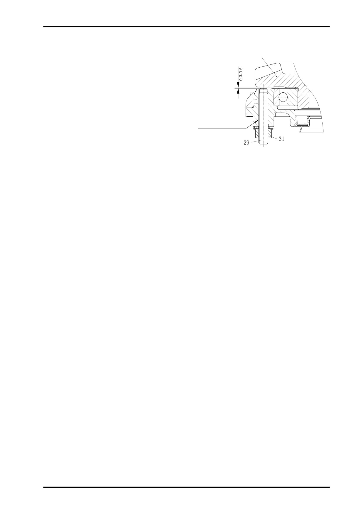
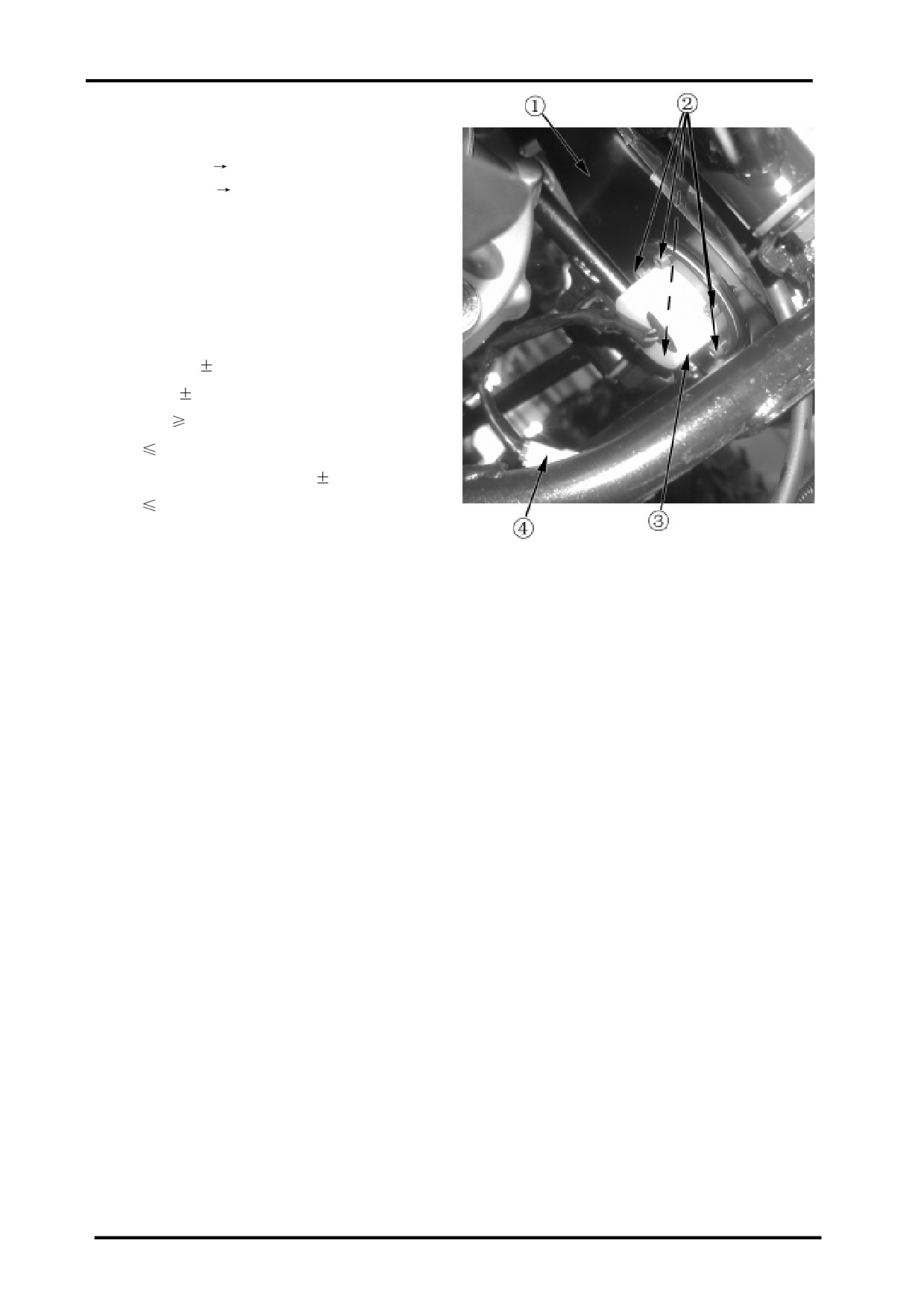
f Adjust item “29” as illustrated, and make sure the
Ring Gear
distance between its end and back of the ring gear is
0.3~0.6. Tighten item “31”.
Apply threadlocker here
14-11
15 ELECTRICAL SYSTEM
Charging System…… ……………………………… ………………… ………………… …
15-2
Start ing Syst em……………… ……………… …………… ……………… ……………… ………15-4
Electronic Fuel Injection (EFI) System………… …………………………… ………………
15-8
1. EFI Structure… ……………… …………… ……………… …………… ……………… ……15-8
2. EFI Maintenance N otice……………… …………… ……………… ……………… ………15-9
15
3. EFI Service Tools……………… …………………… ………………… ………………… …15-10
4. EFI Components and Function…………… ……………………………… ……………
15-12
ECU
15-12
Throttle Body
15-13
T-MAP Sensor
15- 14
Coolant Temperature Sensor
15-16
Oxygen Sensor
15-17
CPS
15-18
Speed Sensor
15-19
Gear Position Sensor
15-20
Fuel Pump
15-21
Fuel Injector
15-22
Idle Air Control Valve
15-23
Ignition Coil
15-24
5. EFI Self-diagnosis
15-25
MIL
15-25
PDA
15-26
Trouble Code
15-27
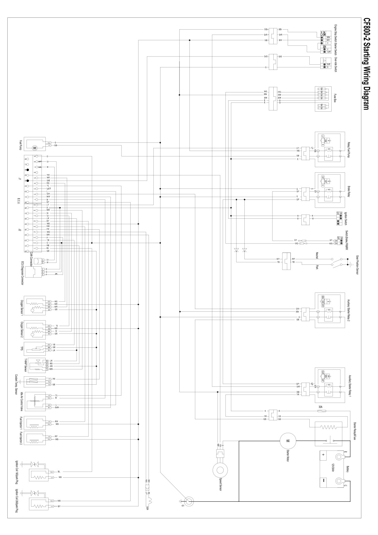
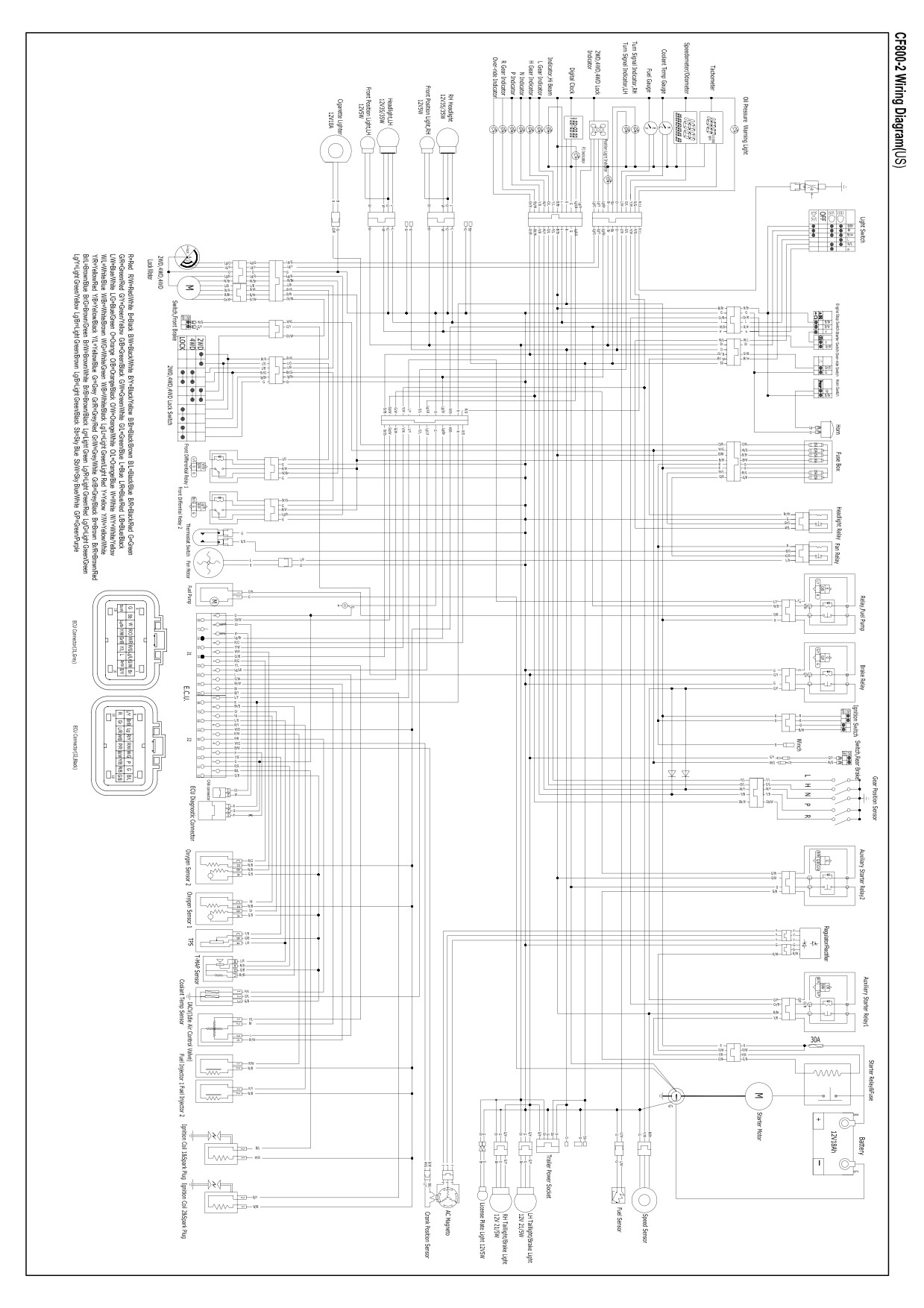
Appendix: EFI wiring diagram, starting wiring diagram, CF800-2 wiring diagram
15
15-1

CHARGING SYSTEM
Charging Circuit
4
5
6
3
1
2
1.Magneto 2.Voltage Regulator/Rectifier 3.Voltage Stablizing 4.Fuse 5.Battery 6.Load
Magneto Coil Resistance
Measure 3-phase magneto stator coil resistance;
If the resistance is out of specification,replace with
a new stator;
Check for the insulation between stator coil and
core.
Turn multimeter to 1X10
MAG Coil Resistance 0.5-1.5
(Yellow-Yellow)
Resistance between Stator Coil and Core:
(Yellow-Ground)
MAG Non-loaded Performance
Start the engine and allow it run at 5000r/min;
Use multimeter to measure the voltage
between 3 output lines.
Ifthe reading is below specification,replace with
a new magneto.
Turn Multimeter to V(AC)
Voltage between Output Lines When MAG
Non-loaded:
>200V(AC) at 5000r/min
15-2

15 ELECTRICAL SYSTEM
VOLTAGE REGULATOR/RECTIFIER
1
2
3
After engine running and at the state of battery
Connect multimeter between terminals;
full charged,if the voltage between positive and
Read resistance;
negative terminal exceeds 15v or is lower 12v,
If any reading is out of specification,
replace with a new MAG.
replace with a new regulator.
Turn multimeter to DIODE.
NOTE:
If multimeter reads below 1.4v when
15
probes unconnected,replace its battery.
(+)
1
2
3
(-)
(+)
1
400-500
2
400-500
(-)
3
400-500
(-)
(+)
400-500
400-500
400-501
750-850
15-3

STARTING SYSTEM
Starting Circuit Diagram
1
3
1.Outer Cover
2.Brush Holder
2
5
3.Brush Spring
4.O-ring
4
5.Brush Terminal
6
6.Main Housing(yoke)
4
7.Washer
8.Armature
9.Washer
10.Cover Inner
11.O-ring
9
7
8
11
10
15-4

15 ELECTRICAL SYSTEM
BRUSH
Check brush for damages,cracks.
If any damages,replace with a new brush.
COMMUTATOR
Check for color change,damages,wear;
If any damages,replace with a new commutator;
If the color changes,poslish the commutator sur
face with sand paper and wipe it up with a clean,
dry cloth.
If over wear,cut a part of insulator B and main
tain the distance betwen A nd B as d.
d
1.5mm
ARMATURE
Use a multimeter to check the armature coil continu-
ity and the one between coil and the shaft.If armature
coil has no continuity or there is continuity between
15
the coil and the shaft,replace the armature with a new
one.
OIL SEAL
Check for damages or leaks.
If damages or leaks,replace with a new starter
motor.
15-5

STARTER RELAY
Put 12V between positive and negative
terminal.
Use multimeter to check if there is continuity
between 2 contacts.
If multimeter clicks,there is continuity between
contacts.
If 12V is removed,no continuity remains between
contacts.
If both above 2 items are ok,it indicates the
replay is ok.
Turn mulitimeter to DIODE.
CAUTION:
The voltage loaded between terminals can not
exceed 2 mins,otherwise,starter relay may over-
heat or burn.
Use multimeter to measure starter relay coil
resistance,if the reading is out of specification,
replace a new relay.
Turn multimeter to 1X10
Starter Relay Coil Resistance:3-5
AUXILIARY STARTER RELAY,FUEL
PUMP RELAY
A
Put 12V between auxiliary starter relay positive and
negative terminal;use multimeter to cheack the
continuity between A and B.
Turn multimeter to DIODE.
If multimeter clicks,it indicates there is continuity
between A and B.
If 12V is removed,no continuity remains between
B
contacts.
If both above 2 items are ok,it indicates the
Ground
replay is ok.
Turn multimeter to
1X100
;measure auxiliary
starter relay resistance.
Auxiliary starter relay resistance
90-100
NOTE:At the back of auxiliary starter relay,parallel to
Battery(+)
diode,it’s the relay coil positive terminal.
15-6
15 ELECTRICAL SYSTEM
ENGINE STARTING NOTICE
Poperly route according to starting schematic
diagram.
Before starting,check if all parts are fitted correct;
Regarding EFI components connection,refer to EFI
section.
Check air intake system.
Check fuel supply system;ensure there is no bolck
or leaks.
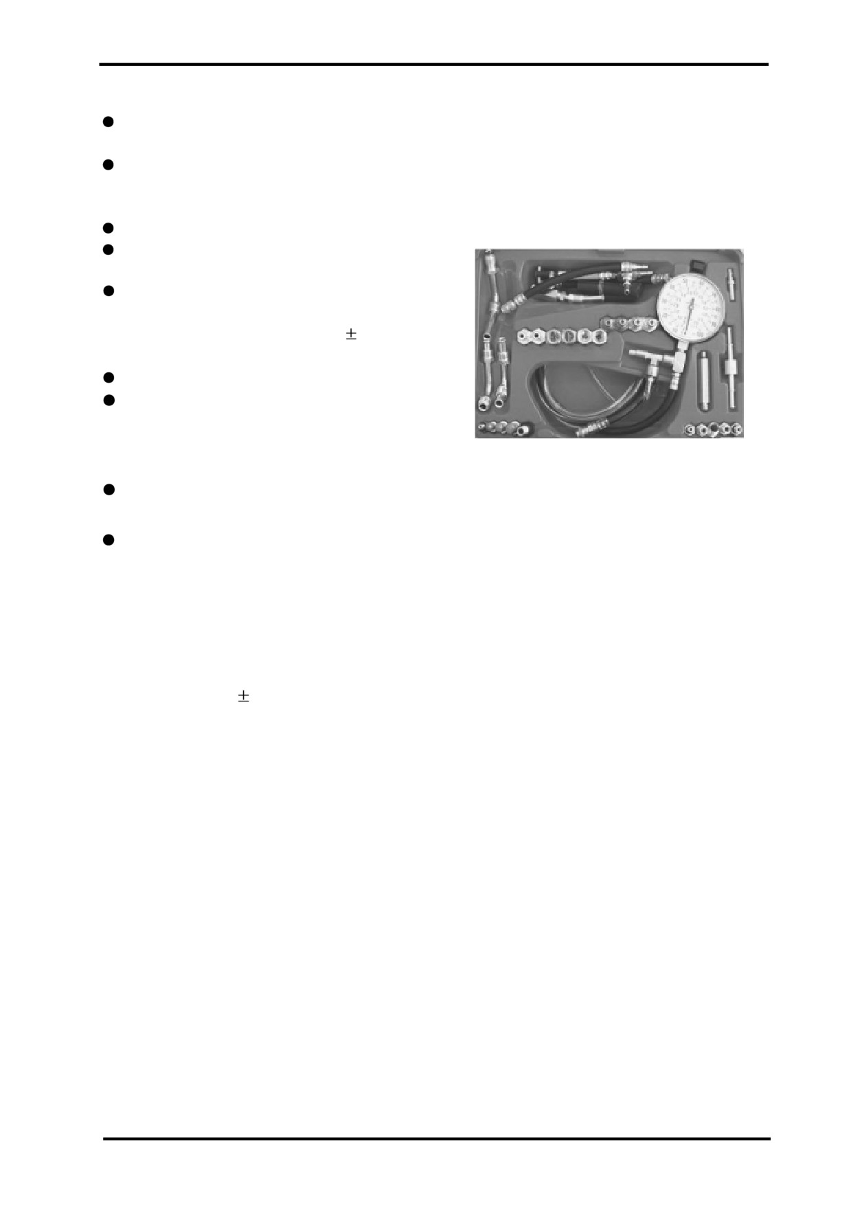
Test fuel presure with fuel pressure gauge.
Pressure in fuel pump outlet:0.33
0.01Bar.
Place the transmission in Neutral.
Check EFI with PDA for faut;if there is,eliminate
the trouble according to DTC(Diagnostic Trouble
Code).
Fuel Pressure Gauge
Close the throttle and turn the engine stop switch
to “RUN”,then push starter switch to run the engine.
After starting,warm up until idle speed is stable and
check it.
NOTE:
If idle speed is unstable or too high,shut off the
15
engine,and then start it.
Idle Speed:1250
100rpm.
15-7

EFI Structure
Idle Air Control Valve
T-MAP Senor
Air Filter
Ignition Coil
Coolant Temp. Sensor
TPS
O2S(Oxygen
Sensor)
CPS
ECU
Fuel Pump
EFI system is composed of three
subsystems:
Sensors:
A sensor is a device that measures a physical
(3)Actuator:
quantity and converts it into a signal which can be
Execute the EFI instruction.Main actuators include:
read by an observer or by an instrument.Sensors in
Fuel Pump
EFI system include:
Fuel Injector
Throttle Position Sensor(TPS)
Ingnition Coil
Crankshaft Position Sensor(CPS)
Idle Air Control Valve
Coolant Temp. Sensor
Speed Sensor
Gear Positon Sensor and Reverse Gear Sensor
Oxygen Sensor
4WD/LOCK
Over-ride Switch
(2)ECU:
Electronic Control Unit,the brain of EFI system,which
determines the amount of fuel injection, ignition tim-
ing and other parameters a engine needs to keep run-
ning by calculating and analysing values provided by
sensors.
15-8
15 ELECTRICAL SYSTEM
EFI System Maintenance Notice
Always use genuine CFMOTO parts for maintenace,
Don’t reverse the battery cable connections.This
otherwise it can not assure a normal performance
may damage electrical components.
to EFI system.
During the maintenance procedure,never try to
Never remove the battery cables When the engine
break down the EFI components.
is running.
In the course of maintenance,EFI parts must be
Always remove cables and electrical control units
handled carefully.
which are connected with battery terminals.
Ignition switch must be shut off before connecting
Never test the component input and output electric
or disconnecting connectors,otherwise,it may
signal by piercing the cable plastic jacket.
cause the EFI parts damage.
When removing fuel pump from fuel tank,do not
Respect the environment and dispose of the waste
energize the fuel pump,otherwise,a spark can
left during maintenance.
cause a fire.
Fuel pump is not allowed to operate in a dry
enviroment or under water,otherwise,it’s life
would be shortened.Besides, reverse connections
between positive and negative terminal of fuel
pump is not permitted.
The fuel pressure in EFI fuel supply system is very
high(about 330kPa),accordingly,all fuel lines are
high pressure resisting.Even if the engine is not
15
running,the fuel pressure is high.Therefore,do not
disassemble the fuel line unless it’s necessary.
When the fuel line needs to be repaired,release
the fuel pressure as follow shows:
Remove fuel pump relay,start the engine and
allow it to idle until the engine stalls
automatically.
Fuel line removal and fuel filter replace ment should
be practiced by a proffessional person in a
well-ventilated place.
If possible,don’t do the spark test.If spark test
is done unavoidably,try to complete the
test as soon as possible.Besides,don’t open the
throttle,otherwise,a large quantity of unburnt fuel
would enter muffler,causing the catalytic converter
damage.
Idle speed is controlled by ECU,so it’s unadjustable.
The throttle limiter screw has been adjusted by
manufacturer before sale,therefore,it’s not
recommended to adjust it by the user.
15-9

SERVICE TOOLS
Tool Name:PDA
Function:
Read/clear EFI system trouble codes,observe
datastream.
Tool Name:Digital Multimeter
Function:
measure voltage, current and resistance
and other parameters in EFI system.
Tool Name:Vaccum Gauge
Function:
Check the manifold for air pressure.
15-10
15 ELECTRICAL SYSTEM
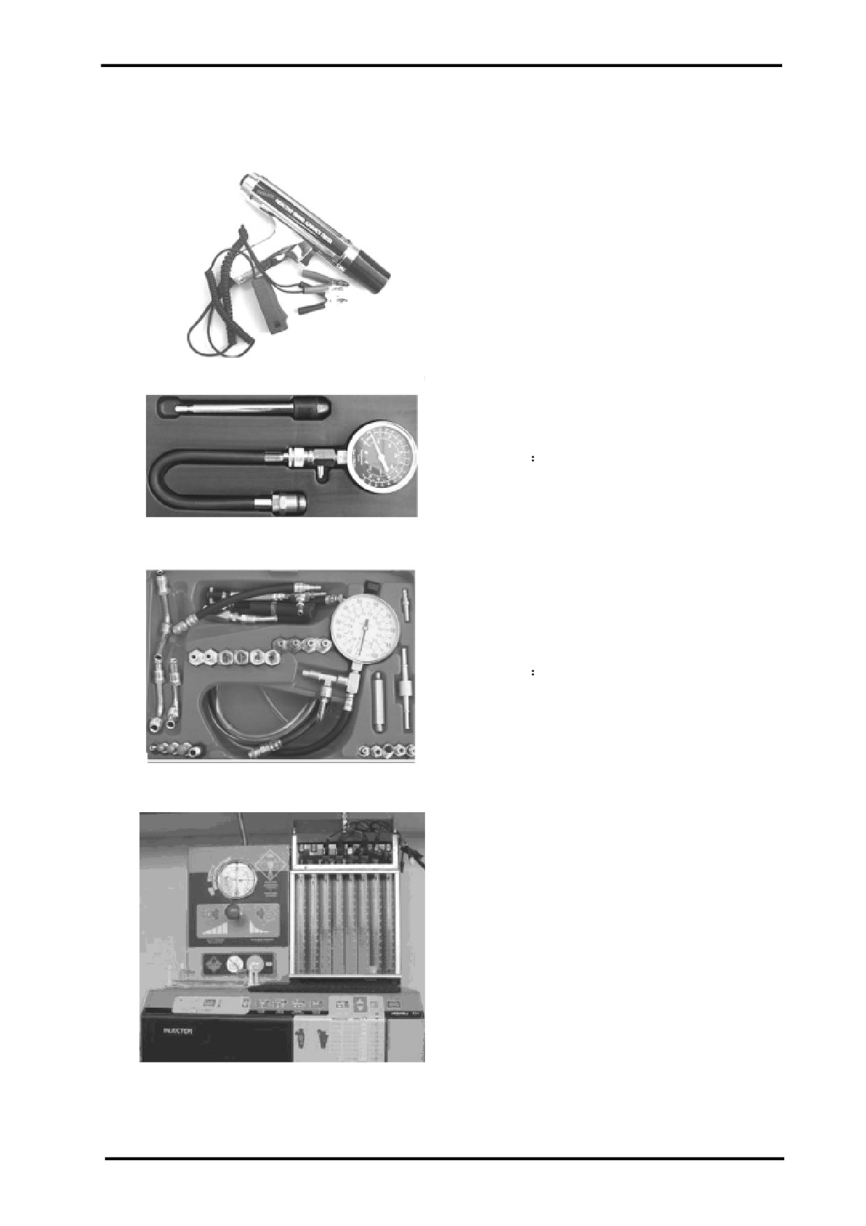
Tool name:Timing Light
Function:
This light is used to check engine ignition timing.
Tool name:Compression Tester
Function
This tester is used to check cylinder compression,so
as to determine if the rings or valves are bad and leak-
ing pressure.
Tool Name:Fuel Pressure Gauge
15
Function
This gauge is used to test the fuel pressure,so as to
check fuel pump and fuel pressure regulator working
conditions.
Tool Name:Fuel Injector Analyser
Function:
This analyser is used to clean and analyse fuel
injectors.
15-11
EFI COMPONENTS AND FUNCTION
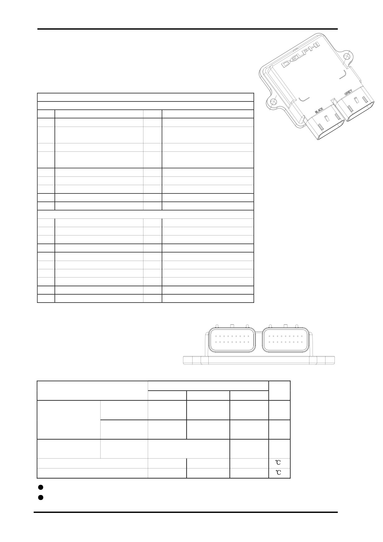
(1)ECU:
ECU pins and function:
PINOU T CH ART
J1 CONNECTOR
PIN#
Description
PIN#
Description
J1-1
IACVHI/IAV
J1-10
COILB/ESTB
J1-2
MAGNETO
CUT
J1-11
IACALO
RELAY/CLTL/ESTC
J1-3
MIL
J1-12
IACBHI
ECU
J1-4
DEAD
BATT
J1-13
IACBLO
BYPASS/O2BHTR/INJC
J1-5
SPARE ANALOG
J1-14
ROLLOVER
J1-6
TACHOMETER
J1-15
VSS/02B SENSOR
J1-7
CANLO
J1-16
DIAG
J1-8
CANHI
J1-17
FUEL PUMP RE-CIR
J1-9
GND(POWER)
J1-18
PN SW
J2 CONNECTOR
Pin#
Pin#
Description
J2-1
COILA/ESTA
J2-10
5VRTN
J2-2
GND(POWER)
J2-11
MAP
J2-3
KW 2000
J2-12
TPS
J2-4
CRANK VR HI(23XHIFI)
J2-13
C RANK VR LO(23XLOFI)
J2-5
IN JA
J2-14
CLT
J2-6
IN JA
J2-15
IGN
J2-7
O2A HTR
J2-16
5VR EF
J2-8
IAT-MAT
J2-17
O2A SENSOR
J2-9
FUEL PUMP RELAY
J2-18
VBATT
J2
J1
9
1
9
1
18
10
18
10
ECU Pin Locations:
Limit Data:
Value
Item
Unit
Min
Standard
Max
Operation
9.0
14.0±1
16.0
V
Battery Voltage
Normal
Function
6.0-9.0
16.0-18.0
V
Limited
Withstanded
Limited Function Such As
26.0V
5.0
Min
Overvoltage and Time
Diagnosis
Working Temp
-40
+70
Storage Temp
-40
+70
It’s not allowed to apply a heavy load on ECU housing,or it may deform and damage ECU.
Always handle ECU gentlely.Never drop it,especially on a hard surface.
15-12

15 ELECTRICAL SYSTEM
(2)THROTTLE BODY ASSEMBLY:
Idle Air Control Valve
Connected
with Air Filter
Connected between air filter and engine.When throttle
lever is applied,the valve butterfly in throttle body would
spin at a certain angle.Tps can monitor the position of
valve butterfly and send the signal to ECU.
TPS
Pins and function:
Connected with Air
1.Connected to 5V power
Intake Manifold
2.Ground
Throttle Body Assembly
3.Outout voltage signal
1
2
3
TPS
15
TPS Circuit:
9
1
TPS
ECU
J2
18
16
12
10
Idle speed limiter screw is not allowed to adjust.
Idle speed is regulated by ECU.
Idle Speed
Adjuster Screw
15-13

(3)T-MAP SENSOR:
This sensor integrates Inlet Air Temperature Sensor
and Manifold Absolute Sensor.It’s used to detect both
inlet air temperature and maifold absolute pressure,
providing ECU the signal of engien load.
4 3
2 1
Pins and Function:
1.Ground
2.Connected with 5V power
3.Voltage signal output
T-MAP Sensor
T-MAP Sensor Circuit:
9
1
J1
ECU
MAP Sensor
18
16
11
10
1
4
2
9
8
1
J2
18
10
IAT Sensor
1
3
The right figure illustrates the allowed installation angle
to avoid condensated water built up in T-MAP sensor,
causing pressure sensitive elements damage.
15-14

15 ELECTRICAL SYSTEM
The following figure refers to output volatge-pressure relation.
5
4.65
0.4
0
0
10
115
Absolute Pressure in kPa
The following chart explains resistance-temperature relation.
15
60000
50000
40000
30000
20000
10000
0
-40 -30 -20 -10
0
10
20
30
40
50
60
70
80
90
100 110
120 130
-10000
Temp.(
)
Resistance(OHM)
15-15
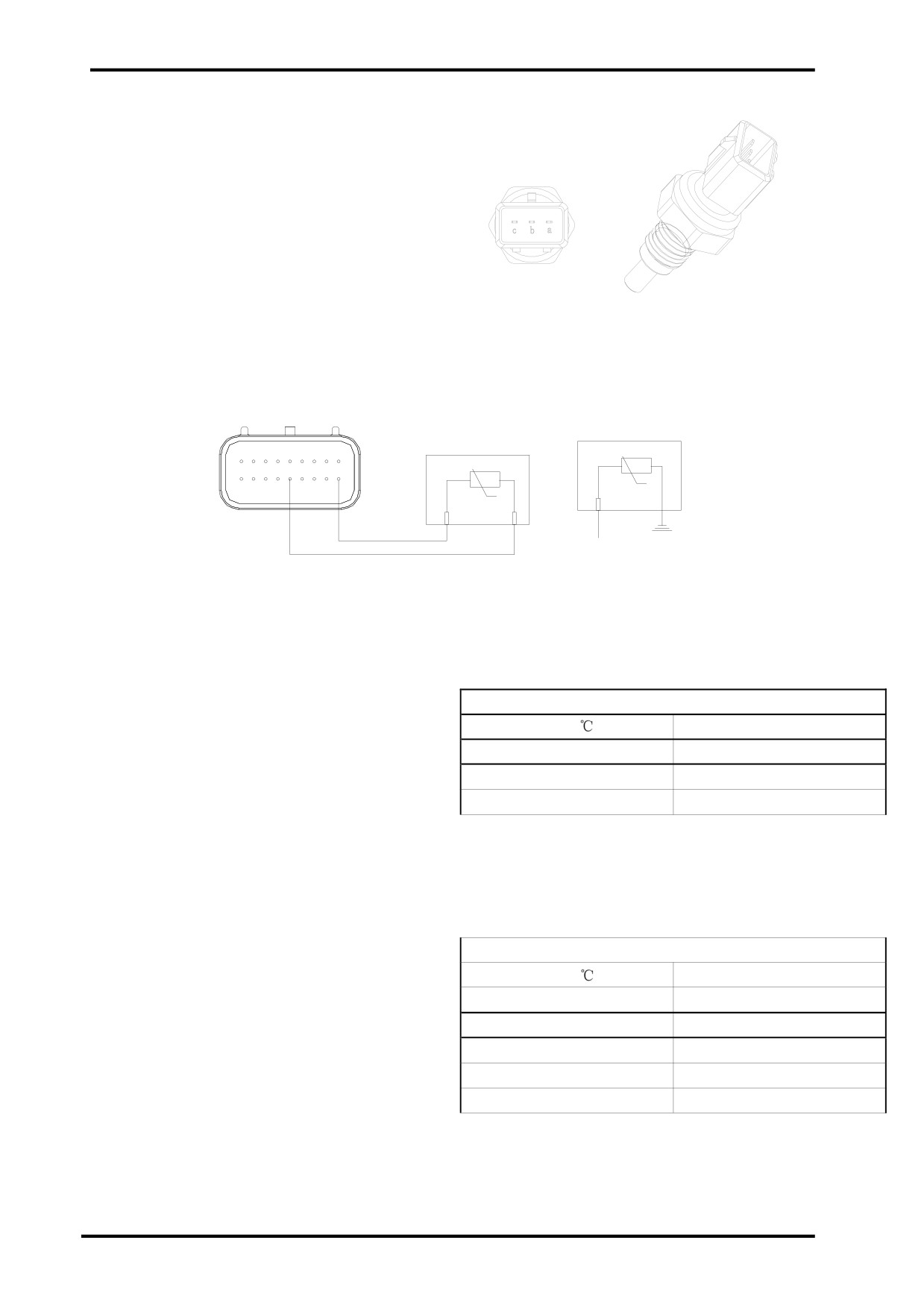
(4)COOLANT TEMPERATURE SENSOR
(CTS):
This sensor is a negative temperature coefficient(NTC)
thermistance,whose resistance increases with the tem-
perature of coolant decreases.It outputs 2 set of
coefficients,one is for ECU to monitor the tempera-
ture of coolant,the other is for meter dispaly.
A and C consists of one group,which provids signal for
ECU.
Coolant Temperature Sensor
B and threaded portion consists of one group,which
provides sigal for coolant temperature gauge.
Coolant Temperature Sensor Circuit:
9
1
ECU
J2
T
18
14
10
T
B
A C
Connected with Meter
The right chart explains pin B and threaded portion-
Meter Channel Resistance(b-Threaded Portion)
coolant temperature relation.
Temp.(
?
)
Resistance(Ω)
45
265.0-323.0
80
74.6-90.6
115
25.7-31.7
The right chart explains pin A,C-coolant temperature
ECU Channel Resistance(a-c)
relation. The siganl is for ECU.
Temp.(
?
)
Resistance(Ω)
-25
38,583
0
9,399
25
2,795
80
334
115
115.7
15-16
15 ELECTRICAL SYSTEM
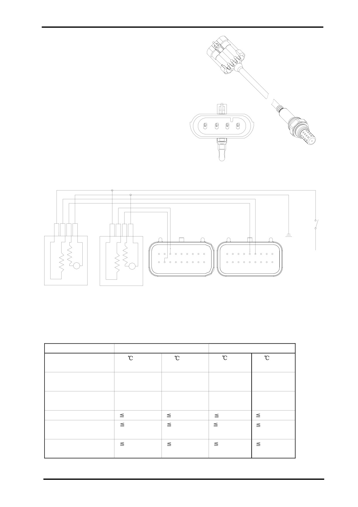
(5)OXYGEN SENSOR:
This sensor is used in closed-loop feedback-controlled
fuel injection to improve the air-to-fuel ratio accuracy
and control the emission.
It’s located in the exhaust stream to measure
the amount of oxygen in exhaust and send the signal to
ECU,which can revise the fuel injector output ,so as to
reduce the amounts of both unburnt fuel and oxides of
nitrogen entering the atmosphere.
Pins and Function:
1.Connected with positive terminal,heating power(white)
D C
B
A
2.Connected with negative terminal,heating power(white)
3.Connected with negative terminal,signal output(grey)
4.Connected with positive terminal,signal output(black)
Oxygen Sensor Circuit:
Engine
Stop
D
C
BA
D
C
B
A
Switch
9
7
1
9
5
4
1
1817
10
18
10
15
J2
J1
ECU
O2S
2
O2S 1
The following table explains the oxygen sensor working parameters.
Parameter
New oxygen sensor
After 500 hours bench test
Exhaust temp. at a
350
850
350
850
certain duty ratio
Sensor voltage
(mv)
840±70
710±70
840±70
710±70
when λ=0.97(Co=1%)
Sensor voltage
(mv)
20±50
55±30
20±50
40±40
when λ=1.10
Sensor inner resistance
1.0
0.1
1.5
0.3
Response
150
150
300
200
time(ms)(600mv-300mv)
Response
150
150
300
200
time(ms)(300mv-600mv
15-17
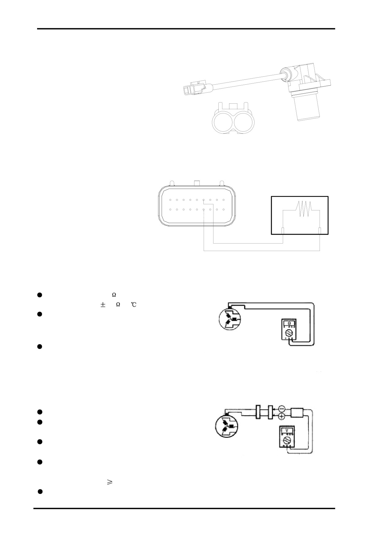
(6)CRANKSHAFT POSITION SENSOR
(CPS):
Detects the rate at which the crankshaft is spinning
and provides the signal for ECU to determine ignition
and fuel injection.
A
B
(+)
(-)
CPS Circuit:
CPS
9
4
1
J2
18
13
10
A
B
ECU
CPS Resistance:
Set multimeter to 1X2K range;
CPS resistance:950
50
(20
)
If the CPS resistance reading is out of specifi
cation above,replace.
Test CPS Peak Voltage
AC Magneto
Connect multimeter and peak voltage adapter as
CPS Resistance
right wiring diagram illustrates;
+Probe: Green Lead
- Probe: Blue Lead
NOTE:
When using peak voltage adapter,refer to some
CPS Peak Voltage Tester
instructions.
Set multimeter to V range;
Place the transmission in N and turn the ignition
switch to ”ON”;
Push starter switch and allow the engine to run for
AC Magneto
seconds,then test CPS peak voltage;
CPS Peak Voltage
Repeat above procedure and get the highest CPS
peak voltage;
CPS peak voltage :
2V (300rpm)
If the CPS peak voltage reading is out of above
specification,replace.
15-18

15 ELECTRICAL SYSTEM
(7)SPEED SENSOR:
This sensor is used to detect the rotating speed of the
engine output shaft and provide the signal for ECU to
determine the vehicle speed. It belongs to Hall effect
sensor,that varies its output voltage in response to a
magnetic field.
Pins and Function:
1
2
1.Ground
3
2.Output voltage signal (>80% input power voltage)
3.Power+DC12V
Speed Sensor
Exterior
+12V Power
The right figure refers to speed sensor wiring:
Ground
1
2
3
ECU
Hall Switch
15
15
Speed Sensor
1
Speed Sensor Test:
2
Ground pin 1and connect pin 3 with +12V power;
3
Fix a gear 2.5mm away from a speed sensor as
the right figure illustrates;
Turn multimeter to DCV range;
Slowly turn the gear and measure the voltage be-
tween pin 2 and pin 3 to determine that if the reading
Gear
2.5mm
varies from 0V-12V;
If the reading doesn’t vary,that indicates the sen-
sor is defective and needs to be
replaced.
15-19
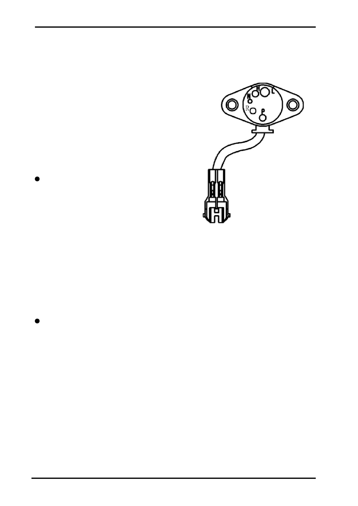
(8)GEAR POSITION SENSOR:
This sensor is used to provide the gear position signal for meter display.
Pins and Function:
Yellow/Blue-L(Low Gear)
Orange/Blue-H(High Gear)
Yellow/Black-P(Park Gear)
White/Yellow-N(Neutral)
Sky Blue/White-R (Reverse Gear)
When each pin at a certain gear position,there is
continuity between this pin and engine.Otherwise,no
continuity.
Gear Position Sensor
(10)CAUTION when driving in reverse
When driving in reverse,gear position sensor sends
the reverse signal to ECU and meter.ECU would limit
the vehicle speed in response to the reverse signal.
15-20

15 ELECTRICAL SYSTEM
(10)FUEL PUMP ASSEMBLY:
This fuel pump assembly includes fuel pump,plastic
12
support,preliminary filter,fine filter and pressure
regulator.It suppies fuel for engine under a certain pres-
sure and flow.
Fuel Outlet
Pins and Function:
1.Blue(Ground)
2.Red(Connected with fuel pump relay output terminal)
Parameters:
Pressure regulator opening pressure:0.33
0.01MPa
Flow:>35L/h
This fuel pump is located in fuel tank;
Don’t operate the fuel pump in dry condition in or-
der to prevent damage.
Always handle the fuel pump gently.Never drop the
fuel pump,especially on a hard surface.Such a shock
to pump can damage it.
Fuel Pump Assembly
Fuel Pump Wiring:
Battery supplies power for fuel pump assembly via
9
1
fuel pump relay,which connects the fuel pump circuit
J2
only with the engine started.
15
18
10
Fuel Pressure Test:
Connect the fuel pressure gauge with fuel outlet
and tighten the joint with a clamp to prevent fuel leaks;
Route according to the right circuit;
Turn both ignition switch engine stop switch on;
At this moment,fuel pump will operate for 5
seconds.After the fuel pump stops running,fuel pres-
Fuel Pump Relay
sure should be in specification,otherwise replace it;
After the engine stops running,0.25MPa fuel
pressue should be kept for more than 5minutes,other-
wise replace the fuel pump;
Power
Pressure Relief in Fuel System:
In an EFI model,the pressure in fuel system is very
Engine
high,so all the line is high pressure resistant.Even
Stop
though the engine is not started,the pressure in fuel
Switch
system remains high.Therefore,it’s not recommended
Ignition Switch
to remove fuel lines before pressure relief.
M
Follow the procedure below to perform pressure relief:
Remove fuel pump relay.Start the engine and allow it
to idle until the engine stops automatically
15-21

(11)FUEL INJECTOR:
Connected with Injector Cap
One end of fuel injector mounts into fuel injector seat,
and the other end attaches to the injector cap,which
connects with a fuel line.Fuel injector is controlled by
ECU to inject fuel at stated time into the engine.
This injector nozzle is a 4-hole style.Don’t turn injec-
tor after the joint between injector and injector cap is
installed.
Pins and Function:
Mark”+”
Connector with the mark”+”:connected with fuel
pump relay output terminal.
Connector without mark:connected with ECU pin 14.
Connected with Injector
Seat
Fuel Injector Resistance:12
1
(20
)
Fuel Injector Exterior
9
65
1
18
10
ECU
Fuel Injector Circuit:
Engine
Stop
Switch
Ignition
Switch
1
2
1
2
Fuel Injector Installation:
Install fuel injector manually.Never knock fuel in-
jector with a hammer.
When removing and installing fuel injector,the o-
Injector 1
Injector 2
rings on both ends must be replaced;
Perform pressure relief before fuel injector removal
if necessary;
Test the fuel injector sealing after installation to
ensure no leaks.
15-22

15 ELECTRICAL SYSTEM
(12)IDLE AIR CONTROL VALVE:
IACV is used to control the air flow of by-pass.ECU
Idle Air Control Valve
calculates the engine load and controLs IACV through
Connected with Air Filter
electrical pulse durationand frequency(commonly
known as duty ratio).IACV allows diffrent air flows
passed through under different pressure diffrences.
Therefore,it should be connected properly,otherwise,
idle speed may be incorrect.When there is no electri-
cal pulse,IACV would be closed.
TPS
Pins and Function:
1.Pin A:IACBLO-ECU J1-13;
2.Pin B:IACBHI-ECU J1-12;
Connected with Manifold
3.Pin C:IACALO-ECU J1-11;
4.Pin D:IACAHI/IAV-ECU J1-1;
9
1
ECU
J1
18
10
Idle Air Control Valve Circuit:
1
2
3
4
15
Idle Air Control Valve
Idle Air Control Valve Parameters:
Value
Unit
Item
Min
Standard
Max
Rated Voltage
13.5
V
Resistance(+20?
)
16
Ω
Rated Current
0.85
A
Control Pulse Frequency
30
Hz
Standard Control Pulse Width
≈8
ms
Air Flow(When Pressure
Difference=700mbr,
5.0
m3/h
Duty Ratio=100%)
15-23

(13)IGNITION COIL
Ignition coil transforms the low voltage of primary coil
to high voltage of secondary coil needed to spark the
spark plug and ignite the mixture of air and fuel in
cylinder.
Pins and Function:
1.Ignition coil (-) of cylinder 1 connected with pin 1,ECU J2;
1.Ignition coil (+) of cylinder 1 connected with battery(+);
3.Ignition coil (-) of cylinder 2 connected with pin 10,ECU J1;
4.Ignition coil (+) of cylinder 2 connected with battery(+);
Connected with High Tnesion Lead
J2
9
11
18
10
ECU
Ignition Coil 1
Ignition Coil Circuit:
9
1
18
10
Engine
Stop
J1
Switch
Ignition Coil 2
Secondary Ignition Voltage Test:
Connect the engine according to EFI wiring diagram;
Peak Voltage Tester
V
Connect the peak voltage tester according to the
right diagram;
Start the engine;
Secondary ignition voltage should be >15000V.
Battery
ECU
Spark Plug
Ignition Coil Parameters:
Item
Value
Unit
Min
Standard
Max
Stated Voltage
14
V
Operating Voltage
6
16.5
V
Resistance
Primary Winding Resistance
0.74
0.76
0.78
Ω
( 20-25℃
)
Secondary Winding Resistance
10.1
10.6
11.1
KΩ
Primary Current
7
A
15-24

15 ELECTRICAL SYSTEM
(14)EFI SELF-DIAGNOSIS:
ECU constantly monitors sensors,actuators,circuits,MIL and battery voltage,etc,even itself.It also tests sen-
sors output signal,actuator drive signal and inner signal(such as closed-loop control,coolant temp. signal,idle
speed control and battery voltage control,etc for reliability ).If any malfunction or suspectable signal found,
ECU would record the fault information in RAM.
Fault information comes in form of fault codes,which are then displayed on PDA, in sequence of which fault
comes first.
Fualt can be divided into “steady fault” and “occasional fault” (such as a fault caused by harness short or loose
connection.)
PDA or MIL can be used to locate the part in trouble immediately after fault happens.
(1)MIL(or FI Indicator):
MIL is a light-emitting diode and located on instrument panel.
It indicates different fault codes through the flashes in differ
ent frequency.
Resistance
MIL Circuit:The current in pin 3,ECU J1 should be
J1-3
less than0.1A.
+12V Power
LED
MIL Flash Principles:
J1-9
(1):Turn ignition switch on and depress kill
J2-2
switch.Don’t run the engine.If no malfunc-
tion happens.
ECU
MIL turns on for 5 seconds,then turns off.
(2):Turn ignition switch on and depress kill
switch.Don’t run the engine.If malfunction
happens.
15
MIL turns on for 5 seconds and turns off.Then MIL
flashes to indicate a fault code:
The interval between fault codes is 3.5s,between dig-
its is 1.2s,and a flash lasts for 0.4s as well as the
interval between 2 flashes.
MIL fashes 10 times to indicate 0.From 1-9,how much
it counts,how many times MIL flashes.
Take fault codes P0117 and P0232 for example:
MIL lights up for 5 seconds turns off and lasts for 3.
5s flashes for 10 times(the frequency is 0.4s)
turns off and lasts for 1.2s flashes once turns off
and lasts for 1.2s flashes once turns off and lasts
for 1.2s flashes for 7 times turns off and lasts for
3.5s flashes for 10 times turns off and lasts for
1.2s flashes for 2 times turns off and lasts for 1.
2s flashes for 3 times turns off and lasts for 1.2s
flashes for 2 times.
(3):Turn ignition switch on and run the
engine.Malfunction happens.
MIL lights up until malfunction disappears.
15-25
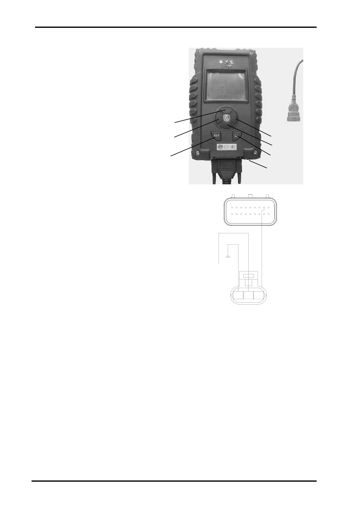
(2)PDA:PDA has 3 pins-power,ground wire and data
cable K.Thses pins are connected with related ECU
pins.
The right photoe refers to operation panel of PDA.When
it comes to detailed keys function,refer to PDA in-
struction book.
Pins and Function:
1.Connected with pin 3,ECU J2;
2.Ground
UP
1 2 3
3.Connected with +12V power
RH Selection
LH Selection
DOWN Key
Keys and Function:
EXIT
OK Key
LH Key:Page up
Power Switch
UP Key:Scroll Up
RH Key:Page Down
9
21
J2
Down Key:Scroll Down
18
10
OK Key:Entrance
EXIT Key:Exit
Connected with
Battery(+)
PDA Function:
(1)Version Infomation Display
RED
GRN
PPL
PDA can display engine,ECU hardware and soft ware infomation.
(2)Fault Display
PDA monitors IAP sensor,IAT sensor,coolant temperature sensor,TPS,O2S,O2S heater circuit,air-to-fuel
ratio revision,fuel injector,fuel pump relay,CPS,speed signal,idle speed,idle air control valve,system voltage,
ECU,FI indicator and displays the fault code.
(3)Engine Data stream Display
PDA can display battery voltage,RPM,desired idle speed,vehicle speed,coolant temperature,coolant tem-
perature sensor signal voltage,inlet air temperature,IAT sensor signal voltage,inlet air pressure,inlet air flow,
IACV target position,TPS signal voltage,throttle body position,throttle body relative position,canister duty,
charging time,FI pulse width,park
advance angle,O2S voltage,engine relative load,cansiter load,IACV position,atmospheric pressure,altitude
multiplier,engine operation time.
(4)EFI Status Display
Starter switch,main relay,fuel pump relay,idle speed,idle speed,full load status,deceleration activation,
acceleration activation,FI close loop activation,lambda control activation,canister control valve activation,
MIL status.
(5)Actuator Test Function
MIL,fuel pump,IACV,canister control valve,ignition,fuel injection.
15-26
15 ELECTRICAL SYSTEM
FAULT CODE TABLE:
P0107
MAP Circuit Low Voltage or Open
MAP-Manifold Absolute Pressure
P0108
MAP Circuit High Voltage
P0112
IAT Circuit Low Voltage
IAT-Inlet Air Temperature
P0113
IAT Circuit High Voltage or Open
P0117
Coolant/Oil Temperature Sensor
Circuit Low Voltage
P0118
Coolant/Oil Temperature Sensor
Circuit High Voltage or Open
P0122
TPS Circuit Low Voltage or Open
TPS-Throttle Body Position
P0123
TPS Circuit High Voltage
P0131
O2S 1 Circuit Low Voltage
O2S-Oxygen Sensor
P0132
O2S 1 Circuit High Voltage
P0032
O2S 1 Heater Circuit High Voltage
P0031
O2S 1 Heater Circuit Low Voltage
P0201
Injector 1 Circuit Malfunction
P0202
Injector 2 Circuit Malfunction
P0230
FPR Coil Circuit Low Voltage or Open
FPR-Fuel Pump Relay
P0231
FPR Coil Circuit Low Voltage or Open
15
P0232
FPR Coil Circuit High Voltage
P0336
CKP Sensor Noisy Signal
CKP-Crankshaft Position
P0337
CKP Sensor No Signal
P0351
Cylinder 1 Ignition Coil Malfunction
P0352
Cylinder 2 Ignition Coil Malfunction
P0505
Idle Speed Control Error
P0562
System Voltage Low
P0563
System Voltage High
P0650
MIL Circuit Malfunction
MIL-Malfunction Indicator Light
P1693
Tachometer Circuit Low Voltage
P1694
Tachometer Circuit High Voltage
P0137
O2S 2 Circuit Low Voltage
P0138
O2S 2 Circuit High Voltage
P0038
O2S Heater 2 Circuit High Voltage
P0037
O2S Heater 2 Circuit Low Voltage
P0500
VSS No Signal
VSS-Vehicle Speed Sensor
P0850
Park Neutral Switch Error
P0445
CCP short to high
P0444
CCP short to low/open
15-27


16 LIGHTS,INSTRUMENT,SWITCHES
Maintenance Info
16-1
Handlebar Switches
16-7
Troubleshooting
16-2
Brake Light Switch-Horn
16-8
Bulb replacement
16-3
Fuel Sensor
16-9
Dashboard- Headlight
16-5
Fuel pump
16-10
16
16
Ignition Switch
16-6
Maintenance Information
Operation Cautions
WARNING
z Headlight bulb will be very hot when it is turned on. Do not touch it after it is just turned off.
Operation should be done when the bulb is cooled down.
z The temperature of headlight is quite high when turned on. Replacing with bare hand or stained glove will
leave oil residue on the glass face which may form hot spot and cause deformation of glass face and
damage to bulb.
z Pay attention to the following when replacing the bulb.
Do not replace the bulb when it is turned on. Keep ignition switch in the OFF position, and replace after the
bulb is cooled down.
-Replace the bulb with hands in clean gloves to avoid oil rsidue on the glass surface.
-Clean the glass with a clean rag dipped in alcohol or isoamyl acetate in case of any oil residue on the glass
surface.
z If the inspection has to be done with battery, check if the battery is normal.
Inspection of switch continuity can be done without removing switches from the vehicle.
z After the inspecting and maintenance of each part, cables and wires should be routed properly (chapter 1).
Refer to Chapter 2 for removal and installation of taillight and rear turning lights.
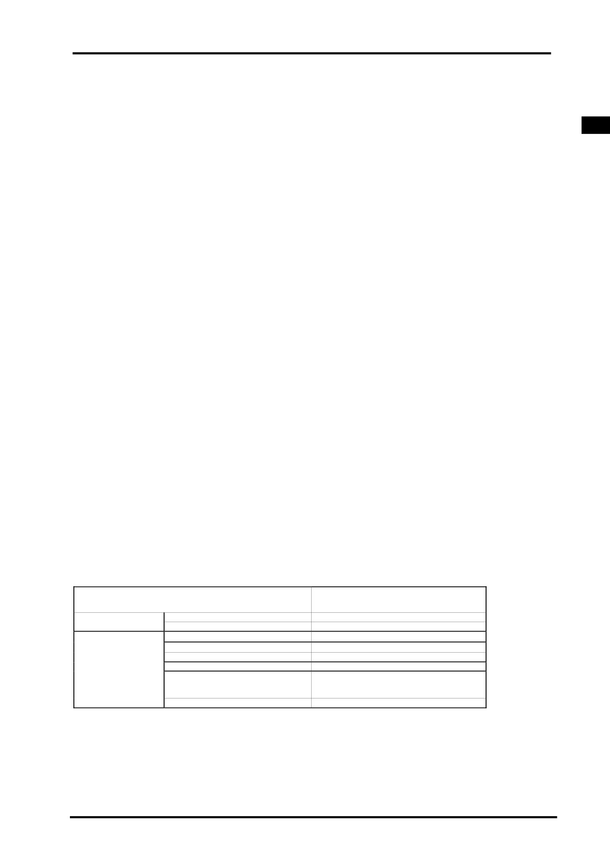
Maintenance Specifications
Item
S ta n da rd
Main
20A
Fuse
Auxiliary
10A×1
15A×5
Headlight( Hi/ Lo)
12V-35/35W×2
Brake light/ Taillight
12V-21/5W×2
Turn Light
12V-10W×4
Panel Light
LED
Light
Coolant
temp.,Fuel
LCD
level,2WD/4WD
indicator
light
MIL
LED
16-1
Troubleshooting
Head Light Cannot Turn On
z Blown fuse
z Open circuit of main cable
z Burnt bulb
z Defective switch
16-2

16 LIGHTS,INSTRUMENT,SWITCHES
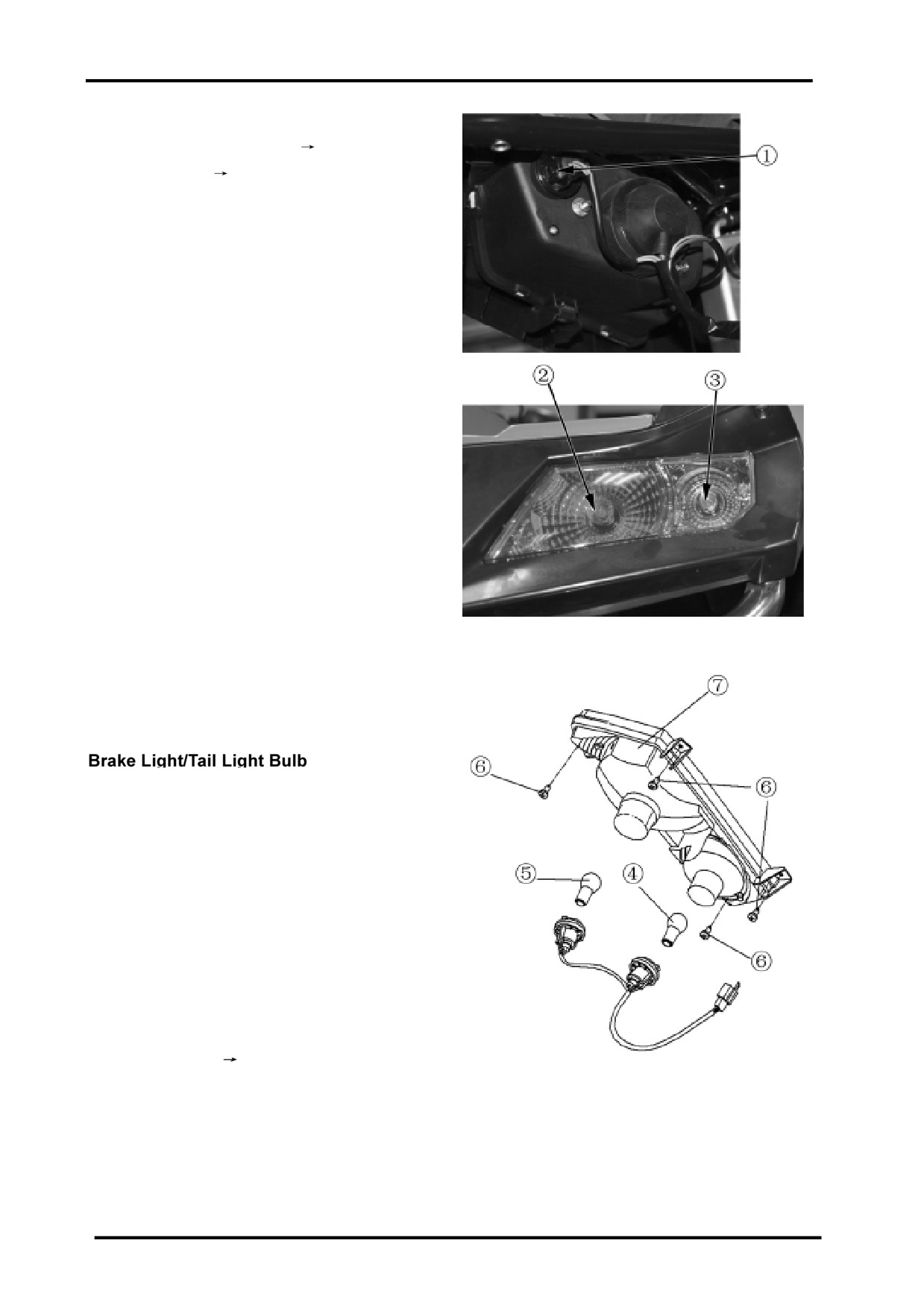
Bulb Replacement
Headlight Bulb
Cautions
Headlight bulb will be very hot when it is turned on.
Do not touch it after it is just turned off.
Operation should be done when the bulb is cooled
down.
Remove left headlight protector (
2-11);
Remove headlight(
16-5);
Remove left position light(front) no.1;
Remove headlight bulb (left) no.2;
Remove left turn light no.3;
Unplug headlight connector;
Remove dust-proof cap, headlight connector,
circlip and replace with a new bulb.
WARNING:
Wear clean gloves when replacing bulb.
Oil residue on the glass surface may cause
the bulb break.Clean the stained surface with
alcohol or isoamyl acetate.
9
Align the three pins of the bulb with the three
7
positioning holes in the
6
socket when replacing the bulb.
4
2
5
Bulb no.7 specification:12V-35/35W
3
3
Bulb no.6 specification:12V-5W
1
2
Bulb no.5 specification :12V-10W
8
2
Reverse the removal procedure for installation
After replacing the bulb, adjust headlight beam
(
3-14).
Headlight Inspection
Turn the ignition switch to ON position,
turn light switch to the illumination
position and check if the headlight is on.
-ON: Normal
-Still off: short circuit of main cable or
broken main cable
16-3
Front Turn Light Bulbs
Remove LH headlight protector(
2-11);
Remove headlight(
16-5);
Remove front turn llight no.1;
Rmove front turn light bulbs.
Bulb Specification:12V-10W
Rear Turn Light Bulbs
Remove rear turn light cover;
Remove rear turn light bulbs;
Replace rear turn light bulbs no.4;
Bulb Specification:12V-10W
Reverse the removal procedure for installation.
Remove tail light cover;
Remove brake light/tail light bulb no.5;
Replace brake light/tail light bulb;
Bulb Specification:12V-21/5W
Reverse the removal procedure for installation.
NOTE:
Main cable,wiring and tube should
be routed properly( Chapter 1).
16-4
16 LIGHTS,INSTRUMENT,SWITCHES
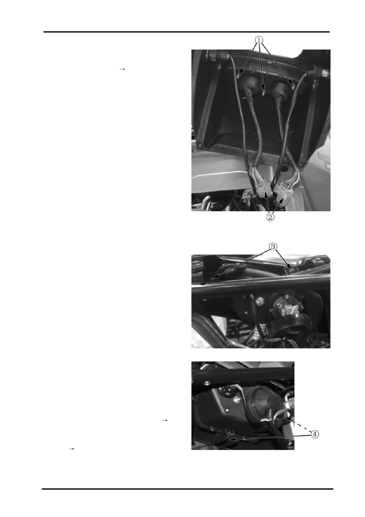
Dashboard
Remove cover of dashboard(
2-5);
Remove nuts no.1;
Remove dashboard connectors no.2;
Remove dashboard.
NOTE: If dashboard has something wrong,
it’s recommended to replace the whole dashboard.
Reverse the removal procedure for installation.
Headlight
Remove cover of headlight (-2-11);
Remove screw no.3;
Remove screw o.4;
Disconnect headlight connector;
Disassemble headlight comp.
Reverse the removal procedure for installation
NOTE:
Be careful not to damage main cable when
assembling.
After replacment, adjust the headlight beam(
3-14);
NOTE:
Main cables and wires should be routed
properly.(
1-20)
16-5

Ignition Switch
Inspection
Remove dashboard cover(
2-5);
Disconnect 4P connector of ignition switch;
Check according to the following table if
the connector terminals are in continuity.
z
:Continuityz
ON
z
z
OFF
z
z
P
z
z
R B G B/W
Removal
Remove dashboard cover(
2-5);
Disconnect 4P connector of ignition switch;
Remove bolt and remove ignition switch;
Installation
Reverse the removal procedure for installation.
16-6
16 LIGHTS,INSTRUMENT,SWITCHES
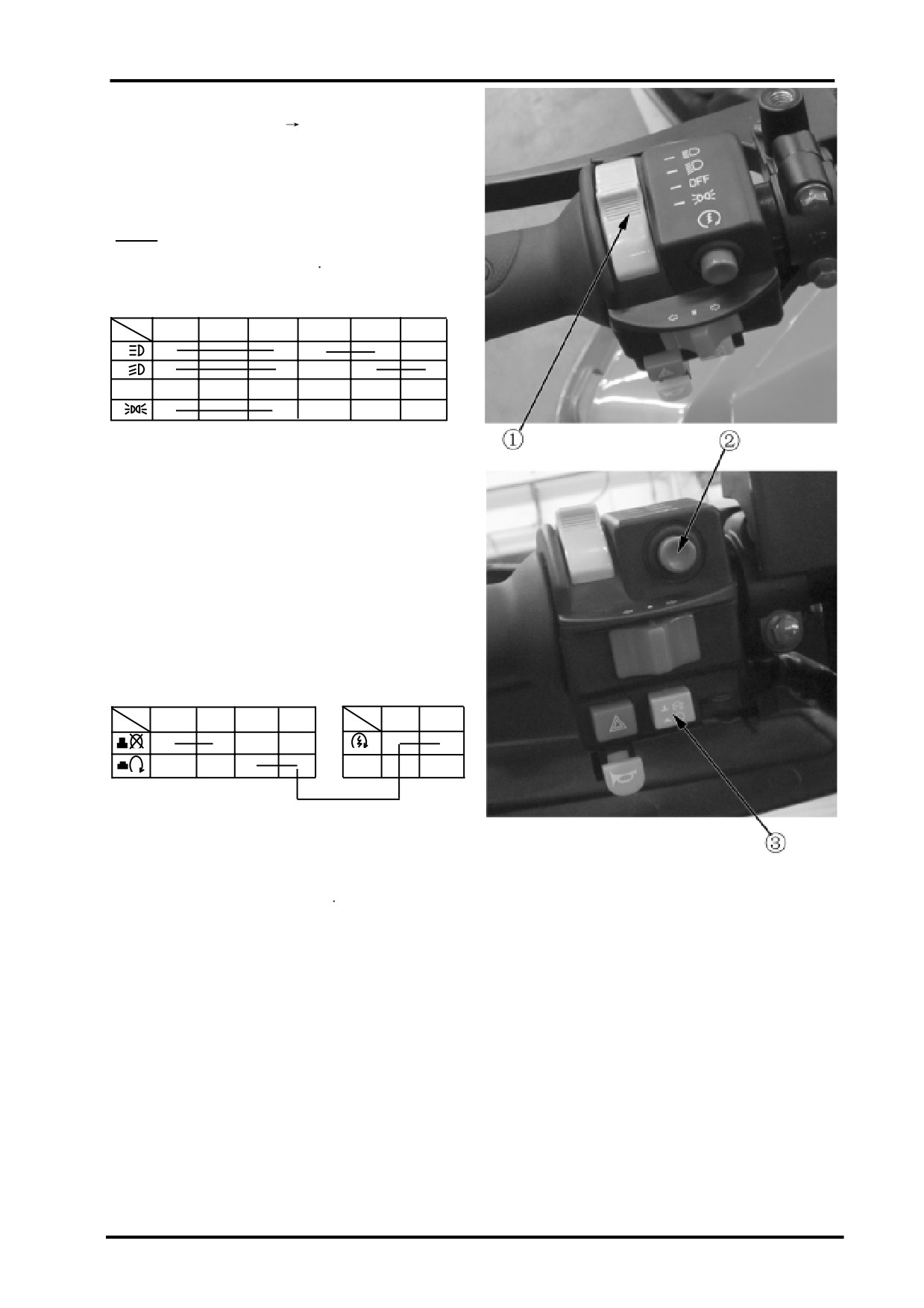
Handlebar Switches
Remove dashboard cover(
2-5);
Disconnect left handlebar switch connectors;
Check according to the following table if
the connector terminals are in continuity.
zz
Continuity
Light Switch no.1
B/Br
Br
Br/W
L
W/L
W
z
z
z
z
z
z
z
z
z
z
OFF
z
z z
B=Black Br=Brown W=White L=Blue G=Green
Gr=Grey R=Red O=Orange Sb=Sky Blue
Lg=Light Green
Kill Switch no.3
Starter Switch no.2
B/W
G
B/Br
Y
Y
Gr/R
z
z
z
z
z
z
16-7

Turn Switch no.1
O
Gr
Sb
L
z
z
PUSH
R
z
z
Horn switch no.3 Over-ride Switch no.4
OFF
OFF
ON
z
z
ON
z
z
Right Handlbar Switch no.5
Br/B
L/G
L/B
Br/G
Gr/W
L/G
Br/R
Br/G
Lg/Br
G
2WD
z
z
z
z
4WD
z
z
z
z
LOCK
z
z
z
z
z
z
If something above wrong, replace
handlebar switches(
12-12).
Hazard Light Switch no.2
Gr/B
B/Br
!
z
z
Brake Light Switch no.6
Disconnect brake light switch connector and
check terminals for continuity.
Brake lever applied:continuity
Brake lever released. no continuity
No continuity: Replace brake light switch
Horn no.7
Inspection
Remove front vent grille (
2-13);
Disconnect horn;
Connect with a fully charged 12V battery
and check if the horn sounds.
Defective Horn: Replace
16-8
16 LIGHTS,INSTRUMENT,SWITCHES
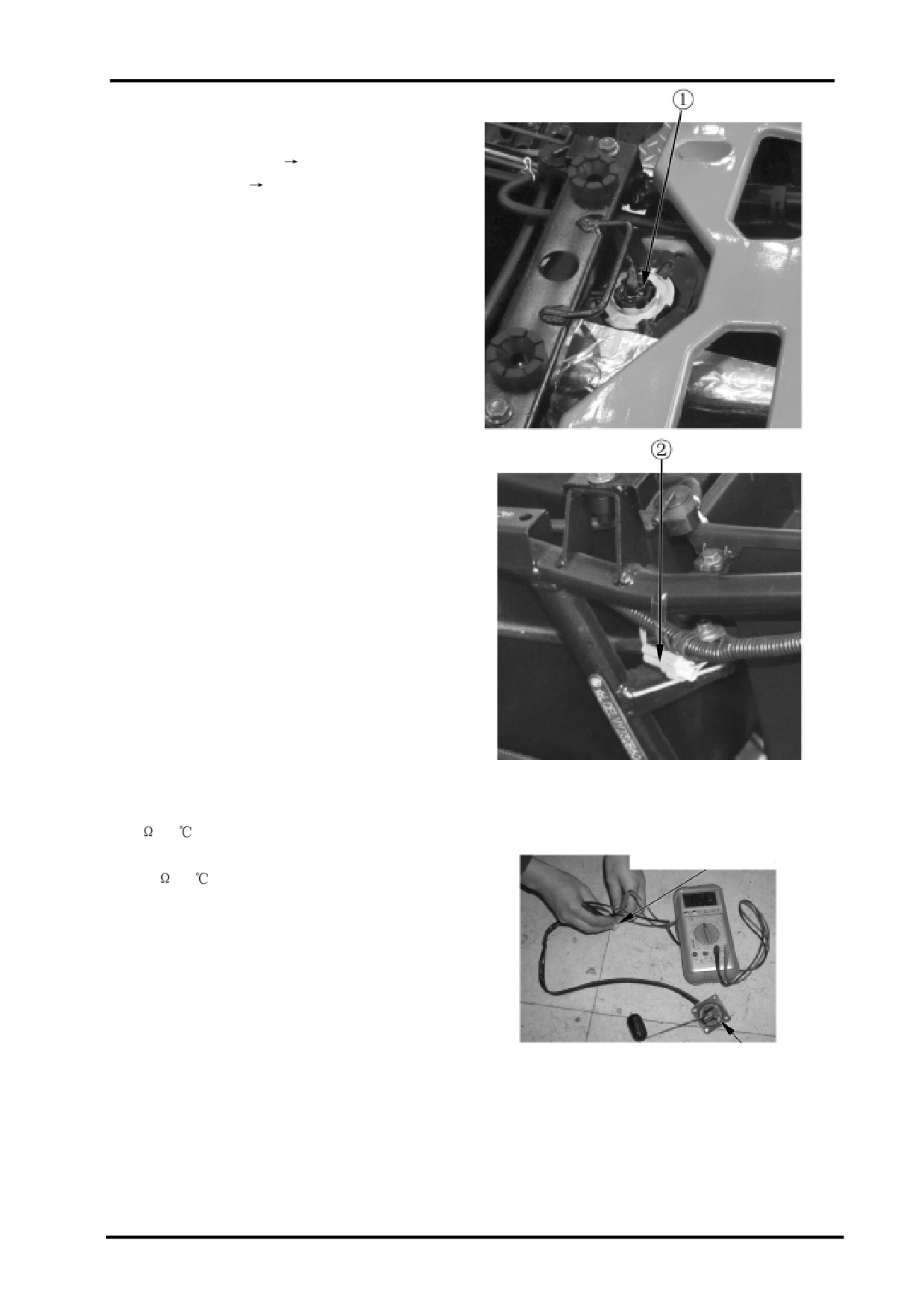
Fuel Sensor
Remove:
Remove passenger seat (
2-4);
Remove driver seat (
2-4);
Remove fuel sensor;
Disconnect 2P connector.
Inspection
Remove fuel sensor (refer to above steps);
Connect 2P connector;
Turn ignition switch to ON;
Shake fuel sensor float with hand, locate the float
position and check if it conforms to the fuel gauge
reading.
Non-conformity: -check main cable for damage or
short circuit
-Check fuel sensor and fuelgauge.
Remove fuel sensor 2P connector;
Connect multimeter between 2P connector
terminals;
Shake float with hand and measure the resistance
of float at different positions.
Connection Terminal:
Upper: Blue/White-Green:
4-10
(20
)
Lower: Blue /White-Green:
Fuel Sensor 2P Connector
90-100
(20
)
Faulty fuel sensor: Replace
Installation
Put fuel sensor into installation hole of fuel tank.
Fuel sensor should be fitted properly.
No fuel leakage is allowed.
Inspection of Fuel Gauge
Switch on power supply and check if fuel
Fuel Sensor
level gauge functions normally.
If fuel gauge works normally,
Reverse the removal procedure for
installation of plastic parts and seat.
16-9
Fuel Pump
Removal
Remove rear seat(
2-4);
Remove front seat(
2-4);
Remove related plastics(see Chapter 2);
Drain fuel in fuel tank ;
Remove the 5 bolts no. 2;
Remove fuel pump no.3 from fuel tank no.1;
Disconnect fuel pump connector.
Fuel Pump Specifications
Voltage:DC13.5
0.3V,
Pressure:0.2
0.01MPa,
Rate of flow
45L/h,
Current
2A,
Regulator working pressure: 0.25
0.01MPa,
Current
2.2A.
Inspection of Fuel Pump
Turn ignition switch to ON and check if fuel
pump functions normally.
If fuel fuel works abnormally,please check if circuit
is open circuit or if EFI system has any problem.
NOTE:
If any probelm of electrical equipment and electrical
system in this chapter ,please refer to chapter of elec-
trical equipment .
16-10
17 TROUBLESHOOTING
1.Engine troubleshooting
17-2
2.Trouble code table
17-6
3.EFI system troubleshooting by trouble code
17-7
4.Trouble diagnosis by engine problems
17-13
17
17-1

17 TROUBLESHOOTING
1.Engine troubleshooting
Trouble
Possible causes
Countermeasures
Engine cannot be started
1.Check electrical system
1) Fuse defective
Check or replace
2) Battery low voltage
Check or recharge
3)Bad wiring connection
Check or replace
2.Check spark plug
1) Ignition coil bad connection or defective
Check or replace
2) High-tension cable bad connection or defective
Check or replace
3) Speed sensor defective
Check or replace
4) Flywheel defective
Check or replace
5) Gap of spark plug incorrect
Adjust or replace
6) Spark plug dirty
Clean or replace
7) Spark plug wet
Dry it or replace
3. Check fuel supply system
1) Canister
2) Fuel pump leakage or defective
Repair or replace
3) Fuel hose leakage
Tighten
4) Fuel insufficient
Check fuel tank
5) Injector blocked or defective
Replace
4.Check cylinder pressure
1) Cylinder worn
Replace
2) Piston ring worn
Replace
3) Cylinder gasket broken
Replace
4) Valve stem worn
Replace
5) Valve seat seal unsuitable
Repair or replace
6) Valve worn
Replace
7) Spark plug loose
Tighten
8) Starting RPM too low
Check or replace
9) Valve timing incorrect
Adjust
10) Valve clearance incorrect
Adjust
5. Air bypass valve blocked or defective
Clean or replace
6. Not shift to “N” gear
Shift to “N” gear
7. Check trouble code
Check
Difficult to start engine
1. Air bypass valve adjustment failure
See engine control system
2. TPS not reset
See engine control system
3. Adjust throttle cable
4. Cylinder pressure insufficient
5. Check spark plug
Check or replace
1) Spark plug defective
2) Spark plug improper installation
Replace defective part
3) Spark plug damaged
4) Spark plug dirty
6. Fuel insufficient or fuel pressure not enough
17-2
17 TROUBLESHOOTING
Trouble
Possible causes
Countermeasures
Engine
1. Coolant insufficient (lower than LOWER line)
Refill coolant
overheating
2. Air bubbles inside cooling system
Remove air bubbles and refill
3. Water temp. sensor defective
Replace sensor
4. Thermostat defective(cannot open when coolant is very
Replace thermostat
hot)
a. Check and replace water
5. Coolant leakage
pump seal
b. Check and replace water hose
● Water hose broken or aging
and clamp
● Clamp loosen
Replace
6. Water impeller damaged
Tighten
7. Water pump cover leaking
Replace
8. Cylinder head cover/Cylinder gasket leakage
Tighten or replace
9. Water pump cover washer leakage
Replace
10. Water pump gear wear or damaged
Replace
11. Water pump shaft defective
Troubles
Possible causes
Countermeasures
Engine oil
1. Check oil level and if any leakage of crankcase or oil seal
Replace and reassembly
consumption
● Crankcase damaged
Replace
too high or
● Tightening bolt loosen
Tighten
oil pressure
● Seal ring or O-ring/washer damaged or broken
Replace
too low
● Piston ring wear (blue spark can be seen)
● Piston ring damaged (compression ratio too low)
Replace
● Oil seal of valve damaged or aging
Replace
2. Oil filter blocked
3. Check oil drain plug screw of crankcase
Replace all oil seal of valves
● Oil drain plug screw loosen
Replace and change oil
● Oil drain plug screw of left crankcase loosen or washer is
missing
Tighten
4. Oil seal of indicator hole is leaking
Tighten or install washer
5. Oil strainer blocked
Replace oil seal
6. Check oil pump
Clean or replace
● Oil pump rotor over-worn
Replace
● Oil pump leakage or damaged by air into oil pump
Replace
● Oil pump gear damaged
Replace
● Engine oil is unsuitable
Use recommended oil
Engine
oil
1. Coolant and oil leaking from leakage indicator hole
Replace oil seal and water
whitening
2. Cylinder head cover and cylinder gasket damaged
seal
3. Bolt of cylinder head cover loosen
Tighten or replace
4. Engine oil impure
Tighten and change oil
Replace damaged parts
(including oil filter and oil)
17-3

17 TROUBLESHOOTING
Abnormal
1.
CVT belt getting narrow
Replace
acceleration
2.
Check drive pulley
●
Rollers wear
Replace
●
Drive pulley track wear
Replace
3.
Drive/driven pulley shaft move not flexibly
Clean or replace
4.
Spring of driven pulley too strong
Replace
5.
Sliders of driven pulley wear
Replace
6.
Groove of drive/driven pulley damaged
Replace
7.
Intake&exhaust valve clearance incorrect
Replace
8.
Compression ratio too low
Adjust
9.
Ignition of spark plug abnormal
Replace
Max. speed too low
1.
Check point 1,2 and 3 of “abnormal acceleration”
2.
CVT system polluted by water, oil and dust
3.
Drive pulley blocked
Clean and replace
4.
Spring of driven pulley weak or damaged
Clean or replace
Replace
Transmission
not
1.
Check bush of drive pulley
good
2.
Check point 1and 2 of “abnormal acceleration”
●
Bush blocked on shaft
Clean and Replace
3.
Check driven pulley
●
Spring of driven pulley weak or damaged
Replace
●
Sliders wear or damaged
Replace
CVT belt over-worn or
1.
Check CVT inlet&outlet air pipe
burned
●
CVT overheating
Clean
●
Drive fixing sheave impeller blocked
Clean
2.
Check pulley groove
●
Dirty oil inside groove
Clean and replace belt
●
Water into CVT case
Clean and replace belt
CVT belt not good
1.
Belt over-worn and getting narrow
Replace
2.
Wrong belt
Replace
3.
Part of belt wear
Replace
4.
Belt broken or over-used
Clean CVT system and
5.
Dirty oil inside groove
replace belt
6.
Drive/driven pulley groove damaged by stone or other
Clean
foreign objects
Clean or replace
7.
Belt aging and getting fragile
Replace
17-4

17 TROUBLESHOOTING
Noise from cylinder head
1.
Valve clearance incorrect
Adjust or replace
2.
Tensioner failure
Replace
3.
Chain guide wear
Replace
4.
Chain extended or chain sprocket wear
Replace
5.
Bolt of sprocket loosen
Tighten
6.
Valve rocker arm or camshaft wear
Adjust or replace
7.
Camshaft timing incorrect
Adjust or replace
Noise from crankshaft and
1.
Bearing damaged
Replace
connecting rod
2.
Plain bearing damaged
Replace
3.
Flywheel rotor loosen
Tighten or replace
4.
Bearing of left crankcase cover wear
Replace
Noise from crankcase
1.
Engine oil leaking
Replace, tighten and add oil
2.
Gear damaged or wear
Replace
Noise from CVT when at idle
1.
Bush of driven pulley blocked or wear
Replace driven pulley
speed
2.
Check drive pulley
3.
Rollers wear
Replace at the same times
4.
Drive pulley track wear
Replace
5.
Drive moving sheave wear
Replace
6.
Nylon sliders wear
Replace
7.
Axial move blocked
Clean or replace
8.
Nut of drive pulley loosen
Tighten
Noise from CVT when at
1.
Check point 1~3 of idle abnormal noise
transmission
2.
Drive pulley dirty and wet
Clean and dry
3.
Nut of drive/driven loosen
Tighten
4.
Driven sliders over-worn
Replace
5.
Belt and cone surface damaged by outside
Clean or replace
materials
CVT drive pulley vibration
1.
Nut of drive pulley loosen
Tighten
2.
Gap of bush of drive pulley too big
Replace
3.
Rollers missing or over-worn
Replace at the same times
CVT driven pulley vibration
Gap of bush of driven pulley too big
Replace
17-5

17 TROUBLESHOOTING
2.Trouble code table
Trouble Code
Trouble Description
Remarks
P0107
MAP Circuit Low Voltage or Open
MAP-Manifold Absolute Pressure
P0108
MAP Circuit High Voltage
P0112
IAT Circuit Low Voltage
IAT-Inlet Air Temperature
P0113
IAT Circuit High Voltage or Open
P0117
Coolant/Oil Temperature Sensor Circuit Low Voltage
P0118
Coolant/Oil Temperature Sensor Circuit High Voltage or Open
P0122
TPS Circuit Low Voltage or Open
TPS-Throttle Body Position
P0123
TPS Circuit High Voltage
P0131
O2S 1 Circuit Low Voltage
O2S-Oxygen Sensor
P0132
O2S 1 Circuit High Voltage
P0032
O2S 1 Heater Circuit High Voltage
P0031
O2S 1 Heater Circuit Low Voltage
P0201
Injector 1 Circuit Malfunction
P0202
Injector 2 Circuit Malfunction
P0230
FPR Coil Circuit Low Voltage or Open
FPR-Fuel Pump Relay
P0231
FPR Coil Circuit Low Voltage or Open
P0232
FPR Coil Circuit High Voltage
P0336
CKP Sensor Noisy Signal
CKP-Crankshaft Position
P0337
CKP Sensor No Signal
P0351
Cylinder 1 Ignition Coil Malfunction
P0352
Cylinder 2 Ignition Coil Malfunction
P0505
Idle Speed Control Error
P0562
System Voltage Low
P0563
System Voltage High
P0650
MIL Circuit Malfunction
MIL-Malfunction Indicator Light
P1693
Tachometer Circuit Low Voltage
P1694
Tachometer Circuit High Voltage
P0137
O2S 2 Circuit Low Voltage
P0138
O2S 2 Circuit High Voltage
P0038
O2S Heater 2 Circuit High Voltage
P0037
O2S Heater 2 Circuit Low Voltage
P0500
VSS No Signal
VSS-Vehicle Speed Sensor
17-6
17 TROUBLESHOOTING
3. EFI troubleshooting by trouble code
Instructions:
1.Only after stable trouble is confirmed, then do checking and repair. Otherwise it will bring mistakes.
2.Below mentioned multimeter is only for digital multimeter, pointer multimeter is not
allowed for checking EFI circuit.
3.If trouble code means voltage too low, it is short circuit to ground or open circuit. If trouble code means
voltage toot high, it is short circuit to power. If trouble code means circuit has something wrong, then
there is open circuit or many circuits in trouble.
Diagnosis helps:
1. If trouble code cannot be removed, then it is stable trouble.
If it is temporary trouble, please check wiring connectors
2. During checking, do not neglect influences of vehicle maintenance, cylinder pressure and valve
timing.
3. Replace ECU and test.
If trouble code can be removed by replacement of ECU, thenitis a trouble originated from ECU. If
trouble code still exists, then install original ECU and check other parts step by step.
In the following, there are detailed descriptions about trouble codes and diagnosis
procedures.
17-7

17 TROUBLESHOOTING
Trouble code:P0032/P0038:Heater coil high voltage of Cylinder 1 and 2 oxygen sensor
Possible causes
Checking procedures
1)Open circuit between ECU and oxygen sensor C
1)Measure resistance between ECU pins and oxygen
pin
sensor C pin, check if it’s ok.
2)Open circuit between main relay and oxygen
2)Measure resistance between main relay and oxygen
sensor C pin.
sensor D pin, check if it’s ok.
3) Open circuit between oxygen sensor C and D pin
3) Measure resistance (9.6KΩ) between oxygen sensor C
pin and D pin.
Trouble code P0031/P0037:Heater coil low voltage of Cylinder 1 and 2 oxygen sensor
Possible causes
Checking procedures
1)Short circuit between ECU and ground.
1)Measure resistance between ECU and ground
2)Short circuit between ECU and oxygen sensor D pin
2)Measure ECU voltage and check if it's ok.
3)Short circuit between ECU and other circuits.
3)Measure resistance (9.6KΩ) between oxygen sensor D
pin and ECU
Trouble code :P0131/P0137:Oxygen sensor low voltage of cylinder 1 and 2
Tips: EFI system can judge output signal if it’s ok by measuring voltage between oxygen sensor A pin and B pin.
Oxygen sensor sometimes will be broken during cold starting.
Possible causes
Checking procedures
1)Short circuit between ECU and ground
1) Measure resistance between ECU and ground and
2)Short circuit between ECU and oxygen sensor D
check if it’s ok.
pin.
2)Measure ECU voltage and check if it’s ok.
3)Short circuit between ECU and other circuits.
3) Measure resistance (9.6KΩ) between oxygen sensor D
4)Oxygen sensor defective, replace it.
pin and ECU
Trouble code : P0132/P0138:Oxygen sensor high voltage of cylinder 1 and 2
Possible causes:
Checking procedures
1)Open circuit between ECU and oxygen sensor A
1)
Replace oxygen sensor
and B pins.
2)
Replace ECU
2) Open circuit between oxygen sensor A pin and B
3)
Wiring checking.
pin
17-8