CFMoto ATV Terralander CF800-2. Service Manual - part 2
STEERING COLUMN
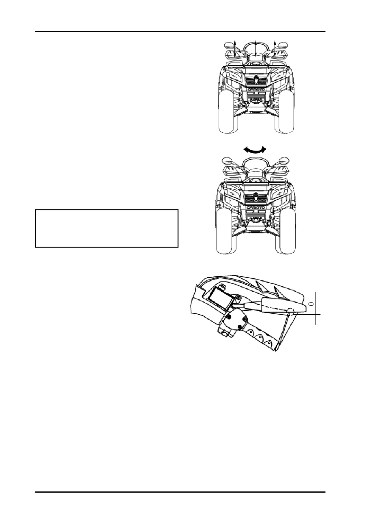
Position the vehicle on level ground.Put your hands
on the grips and shake the handlebar in the direction
illustrated in the right figure to check for free play.
If there is a free play,determine the source of it.
If the free play comes from steering column,tighten
the steering column locking nut or remove steering
column for further inspection and repair.
Position the vehicle on level ground.Turn the handle-
bars slowly to left or right to check for agility.
If the handlebars feel rough when turning somewhere,
inspect the wiring,cables or tie-rod ends for
interference.If no interference,check the steering bear-
ing for damages.
WARNING:
Inspect the agility of handlebars before every
ride.Steering failure may result in severe injury
or death.
BRAKE SYSTEM
Front Brake Lever Free Play
Check the free play of front brake lever and the perfor-
mance of front brake.
Free play of front brake lever:0mm
3-6

3 INSPECTION AND ADJUSTMENT
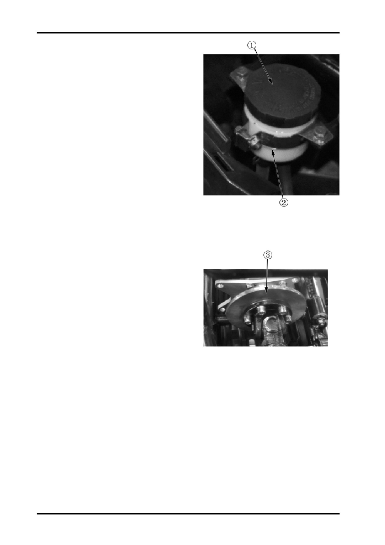
MASTER CYLINDER,FRONT BRAKE
<Brake Fluid Level>
Check brake fluid level.
If the brake fluid level is below the mark”Lower”,check
master cylinder,brake lines and connections for leaks.
Remove the 2 retaining screws no.3 to open the res-
ervoir cap.
Add DOT 3 or DOT 4 brake fluid only.Never exceed
the mark no.1.
z When adding brake fluid,always avoid dirt or water.
z Always use specified brake fluid.
z Don’t spill brake fluid on plastic or rubber parts,as
it would damage them.
z Turn handlebar to left or right to keep the master
cylinder level before the reservoir cap removal.
FRONT BRAKE DISC&BRAKE PADS
<Brake Pad Wear>
Inspect brake pads from the marked place.
Replace brake pads if they are worn to service limit
groove.
CAUTION:
Pads should be replaced as an assembly.
Brake Disc Inspection&Replacement
Inspect brake disc for excessive wear or damage.Re-
place brake disc when its thickness is less than 2.
5mm.
Brake Disc
Front brake disc service limit thickness:2.5mm
Brake Fluid Replacement
<Brake Fluid Replacement>
Replace brake fluid every year.
3-7
MASTER CYLINDER ASEEMBLY,4-
WHEEL BRAKE
<Brake Fluid Level>
Check brake fluid level.
If brake fluid level is below the mark no.2,inspect master
cylinder,brake lines and connections for leaks.
Unscrew reservoir cap no.1 to remove it.
Add DOT 3 or DOT 4 brake fluid only.Never exceed
the mark “UPPER”.
z When adding brake fluid,always avoid dirt or water.
z Always use specified brake fluid.
z Don’t spill brake fluid on plastic or rubber parts,as
it would damage them.
z Turn handlebar to left or right to keep the master
cylinder level before the reservoir cap removal.
REAR BRAKE DISC& REAR BRAKE
PADS
<Brake Pad Wear>
Inspect rear brake pads from the marked place.
Replace rear brake pads if they are worn to service
limit groove.
CAUTION:
Pads should be replaced as an assembly.
Brake Disc Inspection&Replacement
Inspect brake disc for excessive wear or damage.Re-
place brake disc when its thickness is less than 2.
5mm.
Front brake disc service limit thickness:2.5mm
Brake Fluid Replacement
<Brake Fluid Replacement>
Replace brake fluid every year.
3-8

3 INSPECTION AND ADJUSTMENT
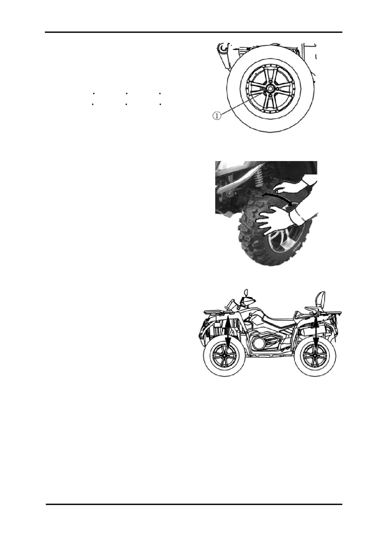
WHEEL
Position the vehicle on level ground.Elevate the ap-
propriate side of the vehicle by plaing a suitable stand
or other tool under the footrest frame.Shake the wheel
to check for free play or looseness.If any free play or
looseness is found,inspect A-arms,axle,rim bolts and
nuts and tighten them if necessary.
If free play or looseness still remains,inspect bearing,
A-arm bushings and ball joint pin and replace if needed.
FRONT Wheel TOE-IN
Position the vehicle on level ground to measure the
front wheel toe-in.
Toe-in:B-A=0-10mm
If the measurement is out of specification,adjust the
tie rod(no.1) locking nuts no.2.
CAUTION:
Drive the vehicle slowly after the adjustment is
completed.Ensure that handlebar works properly.
3-9
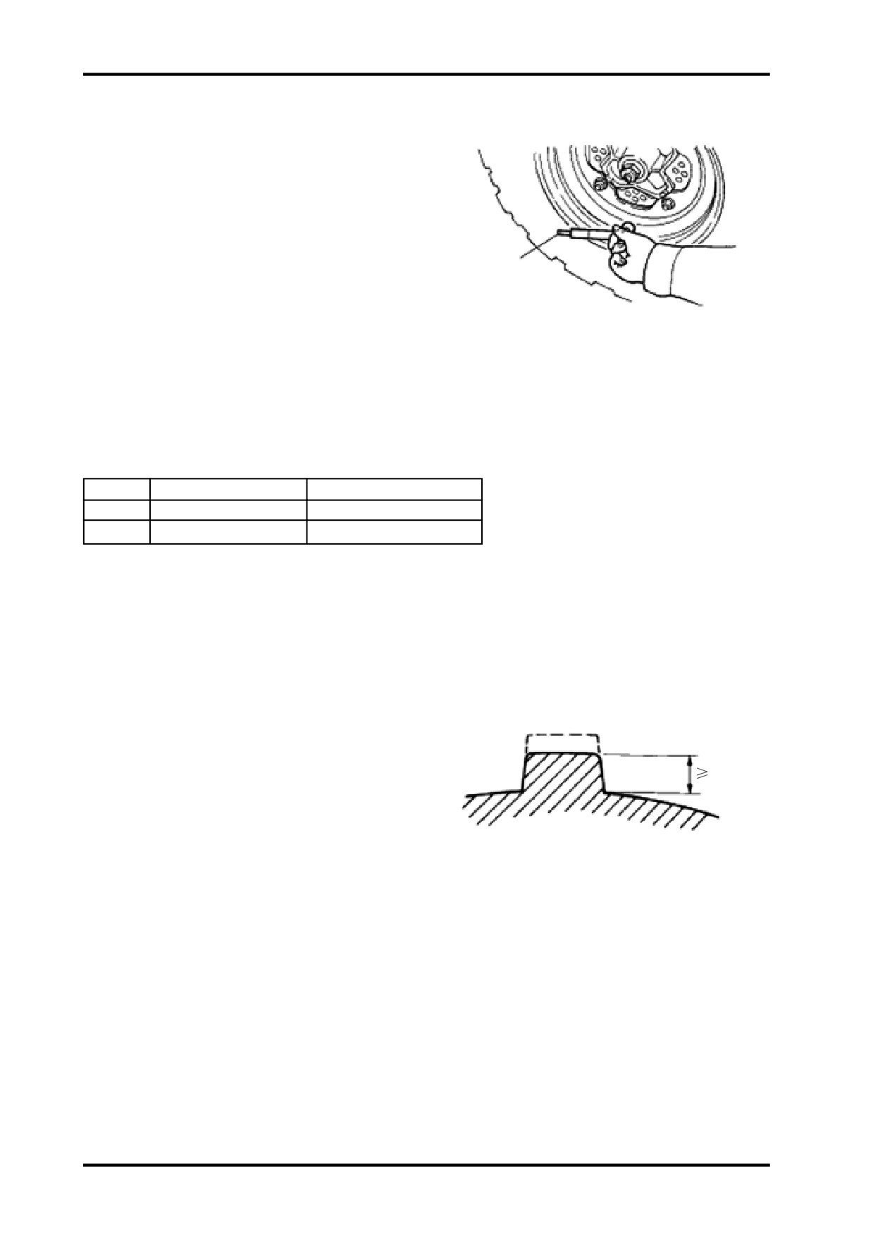
TIRE PRESSURE
Use tire pressure gauge to measure tire pressure.
CAUTION:
Test tire pressure when the tire is cold.
Maintain proper tire pressure.Improper inflation
may affect ATV maneuverability,comfort,or uneven
Tire Pressure Gauge
wear to different tires.
Specified Tire Pressure/Tire
Front
Rear
Pressure
45kPa(0.45kgf/cm2)
45kPa(0.45kgf/cm2)
Size
See chapter 1
See chapter 1
TIRE TREAD DEPTH
Replace tires when tire depth is worn to 1/8”(3mm) or
less.
3mm
CAUTION:
When tire depth is worn to 3mm or less,replace
tires immediately.
3-10
3 INSPECTION AND ADJUSTMENT
AXLE NUTS AND AXLE
Check front&rear axle nuts for looseness.
If axle nuts are loose,torque them to specified values.
Torque Specification:
Front:110-130N m(11.2kgf m-13.3kgf m)
Rear:110-130N m(11.2kgf m-13.3kgf m)
Wheel Bearing Free Play
Elevate the appropriate side of vehicle by placing a suit-
able stand under the footrest frame.Shake the wheel to
check for free play.
If there is a free play,inspect the wheel bearing.
SUSPENSION
Position the vehicle on level ground,push and release
the vehicle as illustrated.If the vehicle found unstable or
abnormal sound,check shocks for leaks,damages or
looseness to fasteners.
3-11

Shock Absorber Adjustment
The front and rear shock springs are adjustable.Ro-
tate the adjuster cam no.2 clockwise to decrease
the spring tension or counter-clockwise to increase
the spring tension.Always adjust two sides equally.
GEARSHIFT LINKAGE
Shift to check gearshift for smoothness.If not,attempt
to adjust the length of gearshift rod by turning the
locking nuts no.3.
FUEL SYSTEM
Fuel System Condition
Remove seat(
2-3);
Check fuel lines for aging,damage;
Replace fuel line if aging,damage found.
Inspect fuel tank breather hose and the hose of fuel
evaporation control system(if appliable) for damages,
bending.Replace the hoses if any damage found.
3-12

3 INSPECTION AND ADJUSTMENT
Throttle Lever no.1 Inspection
Inspect throttle lever no.1 for free play.
Free Play:3
5mm
3-5mm
Adjust throttle lever if free play is out of specification,
Slide sleeve no.3 out of place.loosen throttle cable
locking nut no.2.Turn adjuster to change the throttle
lever free play.
Reinstall locking nut no.2 and throttle cable
sleeve no.3.
If adjuster fails to change throttle lever free play to
specified value,replace throttle cable.
Speed Limiter
Speed limiter is designed to adjust throttle lever travel,
so as to limit the max speed.
Inspect the max length of limiter screw threads
Max limiter screw threads:a=12mm
Adjustment
Loose the locking nut.
Use a cross screw driver to turn the limiter screw
clockwise or counter-clockwise to adjust throttle le-
ver travel.
CAUTION:For beginners,keep the adjuster screw
clockwise turned to the max. For experienced
riders,turn the adjuster screw counter-clockwise
to change the throttle lever travel according to
speed requirements.
3-13
COOLING SYSTEM
CAUTION:
z For safety,check the coolant level in the reser-
voir tank,not radiator.Never open the pressure
cap when the engine is hot(more than 100
),
Escaping steam can cause severe burns.The
engine must be cool before removing pressure
cap.
z Coolant is toxic.Don’t drink nor spill on skin,eyes,
clothing.
If you spill coolant on your skin or clothing,
immediately wash it off with soap.
If you get coolant in your eyes,immediately
wash it off before medical attention.
If you swallow coolant,immediately spit it out
and gargle before medical attention.
z Coolant must be kept out of reach of children.
Coolant Level
Coolant would decrease due to evaporation,etc.In-
spect coolant level periodically.
CAUTION:
z Coolant is anti-rust and anti-freezing.Using tap water
will rust the engine,and may crack the engine
when it’s freezing. Always use specified coolant.
z Position the vehicle on level ground before cooling
system inspection.
z Start the engine and warm it up before inspecting
the cooling system.
Start the engine and warm it up.
Shut off the engine.
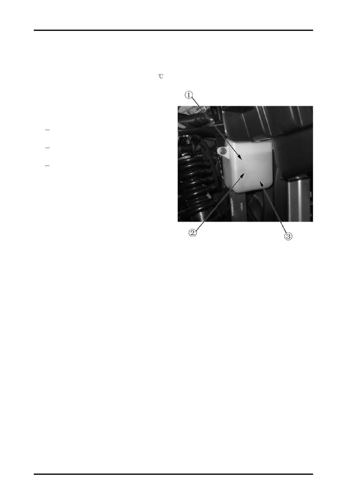
Inspect the coolant level,ensure that the level is be-
tween “LOWER” and “UPPER”.
3-14
3 INSPECTION AND ADJUSTMENT
When the coolant level is below the mark no.1-
”LOWER”,remove the reservoir tank cap and add cool-
ant to the mark no.2-”UPPER”.
Recommended Coolant:CFMOTO coolant.
Standard Mixture Ratio:50%(The freezing tem-
perature varies according to the mixture ratio.
Adjust the mixture ratio according to freeze
protection required in your area.)
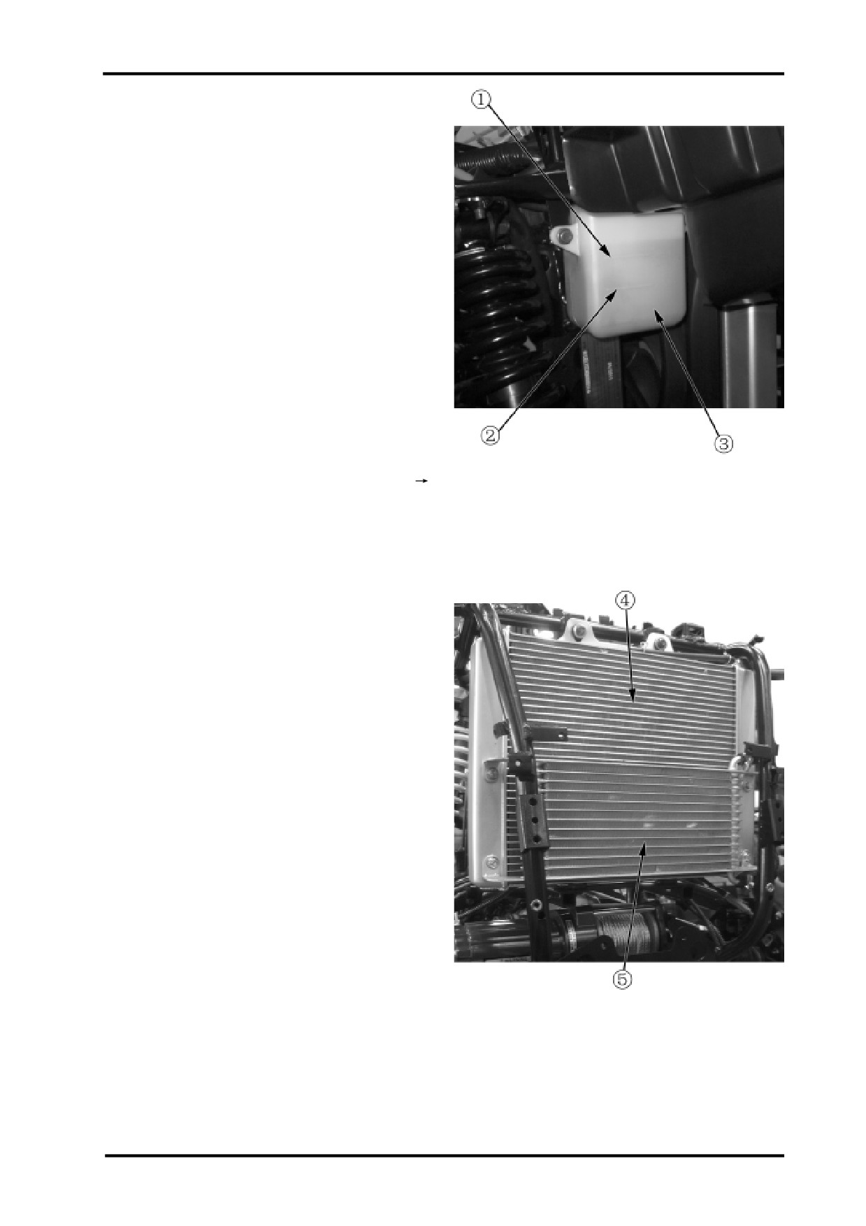
When coolant is reduced significantly,inspect the
cooling system for leaks.If no coolant remains in the
reservoir tank no.3,there may be air in the cooling
system.Purge the cooling system of air.
Coolant Leakage
Inspect radiator hoses,water pump,and connections
for leaks.
If any leaks found,repair the cooling system.(
Chapter 4)
Inspect radiator hoses for aging,damages and cracks.
Hoses ages over time due to special working condi-
tions and may crack.Bend a hose to inspect for
cracks. If any damages or cracks found,replace it
with a new hose.
Inspect coolant hose clamps and tighten the loose
ones.
Inspect radiator fins for damages or mud.
Correct the fin bending.Use tap water or compressed
air to clean off the mud.
The radiator should be replaced when 20% fins are
damaged.
4.Coolant Radiator 5.Oil Radiator
3-15

Coolant Gauge Inspection
The indicator should point at 0 when the engine is not
working.Start the engine to check coolant gauge for
response.If the indicator doesn’t move,determine the
cause and take a repair.
LIGHTING
Headlight Beam Adjustment
Remove headlight protector(
2-11)
In order to adjust headlight beam,adjust bolt no.4 with
a cross screw driver or adjust nut no.3. with a wrench.
3-16
04 COOLING SYSTEM
COOLING SYSTEM
SERVICE TOOLS
4
Description
P/N
Page
Test Cap
9010-180100-922-001
04
Special Puller
0800-014001-922-002
15
Bearing Puller
0800-014001-922-001
15
16
Press Tool,Oil seal
0110-080005-923-001
Press Tool,Bearing
0800-014001-921-003
17
SERVICE PRODUCTS
Description
P/N
Page
Retaining Compound
03
Coolant
05
Engine Oil
16
Loctite 5699
17
04-1
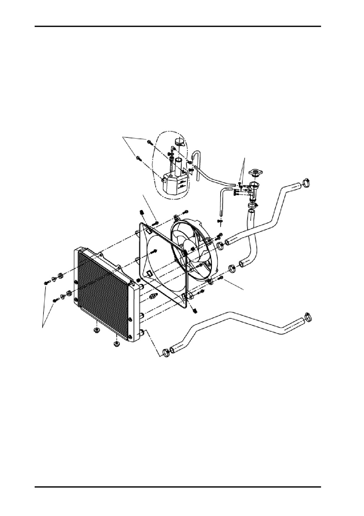
RADIATOR
7 N.m
(62 lbf.in)
7 N.m
(62 lbf.in)
7 N.m
(62 lbf.in)
7 N.m
(62 lbf.in)
7 N.m
(62 lbf.in)
04-2
04 COOLING SYSTEM
WATER PUMP
Engine Oil
Retaining Compound
Loctite 5699
Engine Oil
10 N.m(89 lbf.in)
04-3
GENERAL
WARNING
Never start engine without coolant.Some engine
parts such as the rotary seal on water pump shaft
can be damaged.
During installation,use the torque values and
service products as in the exploded views.
Clean threads before applying a threadlocker.Refer to
LUBRICANTS AND SERVICE PRODUCTS at the be-
ginning of this manual for complete procedure.
WARNING
Torque wrench tightening specifications must
strictly be adhered to.
Locking devices(e.g.:locking tabs,elastic stop
nuts,self-locking fasteners,etc.) must be installed
or replaced with new ones where specified.If the
efficiency of a locking device is impaired,it must
be replaced.
INSPECTION
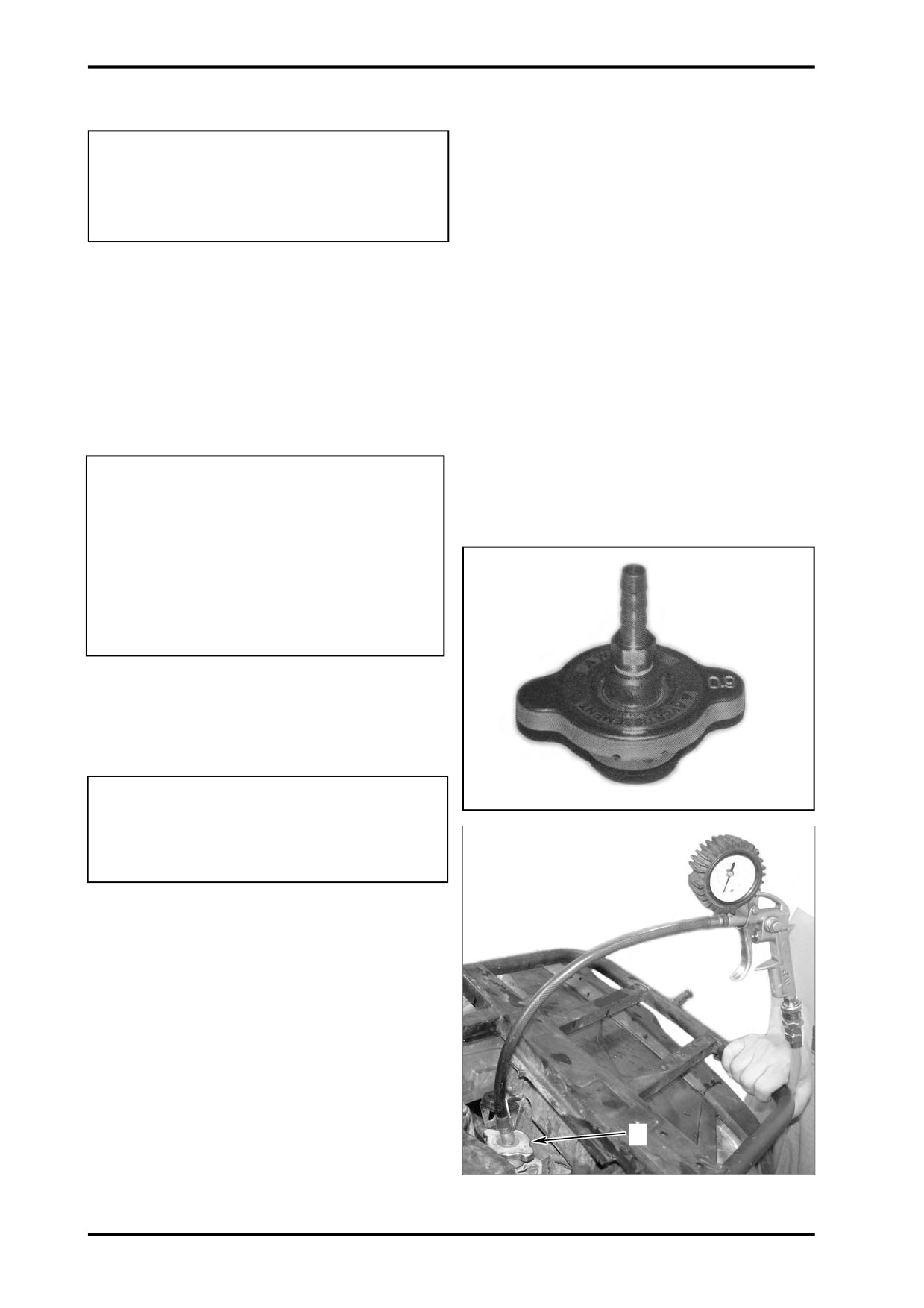
COOLING SYSTEM LEAK TEST
WARNING
To avoid potential burns,don’t remove the radia-
tor cap or loosen the cooling drain plug if the
engine is hot.
Remove battery cover to access and remove radiator
cap.
Install the test cap(P/N 901-18.01.00-922-001 ) on
the filler neck.
Use a pressure/vaccum pump to pressurize system
to 103kpa(15PSI).
Check all hoses,radiator and cylinder(s)/base for cool-
ant leaks or air bubbles.
1
1.Special Radiator Cap.
04-4

04 COOLING SYSTEM
Inspection
Check general condition of hoses and clamps
tighteness.
Check the leak indicator hole if there is oil or coolant.
NOTE:Leaking coolant indicates a defective rotary
seal.Leaking oil indicates a defective inner oil seal.If
1
either seal is leaking,both seals must be replaced at
the same time.Refer to WATER PUMP SHAFT AND
SEALS in this section.
Another leak indicator hole is visible on the PTO side.
It indicates if the PTO gasket is in good condition.If a
1.leak Indicator Hole
liquid leaks by this hole,the PTO gasket replacement
is necessary.
MAINTENANCE
COOLANT REPLACEMENT
WARNING
To avoid potential burns,don’t remove the radia-
tor cap or loosen the cooling drain plug if the
engine is hot.
Use CFMOTO premixed coolant or a blend of 50%
1
antifreeze with 50% water.
To avoid antifreeze deterioration,always use the same
brand.Never mix different brands unless cooling sys-
tem is completely flushed and refilled.
CAUTION:To prevent rust formation or freez-
1.leak Indicator Hole
ing condition,always fill the system with the
CFMOTO premixed coolant or with 50% anti-
freeze and 50% water.Don’t use tap water ,
straight antifreeze or straight water in the
system.Tap water contains minerals and impu-
rities which build up in the system.During cold
weather,straight water causes the system to
freeze while straight antifreeze thickens and
does not have the same efficiency.Always use
ethylene glycol antifreeze containing crrosion
inhibitors specifically recommended for alumi-
num engines.
Draining the System
WARNING
Never drain or refill cooling system when engine is hot.
Remove the radiator cap.
04-5

Partially unscrew cooling drain plug located below
water pump housing.
When cooling system is drained completely,remove
cooling drain plug completely and install a new washer.
Screw the cooling drain plug and torque it to 10N.m
(89Ibf.in)
1
Under LH Footrest
1.Cooling Drain Plug
Refilling the System
Remove related parts.
1
Unscrew bleeding screws on top of thermostat housing.
NOTE:Both two cylinders must be bled
1
1.Bleeding Screws
04-6

04 COOLING SYSTEM
With vehicle on a flat surface,engine cold,refill radiator.
When the coolant comes out by the thermostat hous-
2
ing hole,install the bleeding screw with its washer and
torque to 5 N.m(44 Ibf.in).
Fill up the radiator and intall radiator cap.
1
Fill the reservoir tank and keep the coolant level even at
“LOWER” mark,then install reservoir tank cap.
Run the engine until thermostat opens,then shut off the
engine.
Recheck the coolant level in reservoir tank after the egine
is completely cooled down.Refill coolant if necessary.
Maintain coolant level between “LOWER” and “UPPER”.
1.Washer
2.Bleed ing Screw
NOTE:Each year or every 100 hours or when vehicle
reaches 3000km(1865mi),check coolant concentration
(freezing point) with proper tester.
PROCEDURES
1
THERMOSTAT
The thermostat is a single action type.
3
Thermostat Removal
NOTE:Thermostat is located on the top of cylinder
head,on intake side(front cylinder).
Install a hoe pincher on both radiator hoses.
Remove:
thermostat housing screws and pull thermostat
cover.
1.Thermostat Cover
2.Screws
thermostat with seal ring out of the hole.
1
1.Thermostat with Seal Ring
04-7
Thermostat Test
To check thermostat,put it in water and heat water.
Thermostat should open when water temperature
reaches 65
(149
).
Check if the seal ring is brittle,hard or damaged.If so,
replace the seal ring.
Thermostat Installation
For installation,reverse the removal procedure,pay atten-
tion to the following details.
Install the thermostat cover then torque screws to 6N.m
(53Ibf.in).
Check coolant level in radiator and reservoir tank and top
up if necessary.
CAUTION:
Don’t forget to bleed the cooling system.Refer to
COOLANT REPLACEMENT.
RADIATOR CAP
Using a pressure cap tester,check the efficiency of
radiator cap.If the efficiency is feeble,install a new
110kPa(16PSI) cap(don’t exceed this pressure).
1
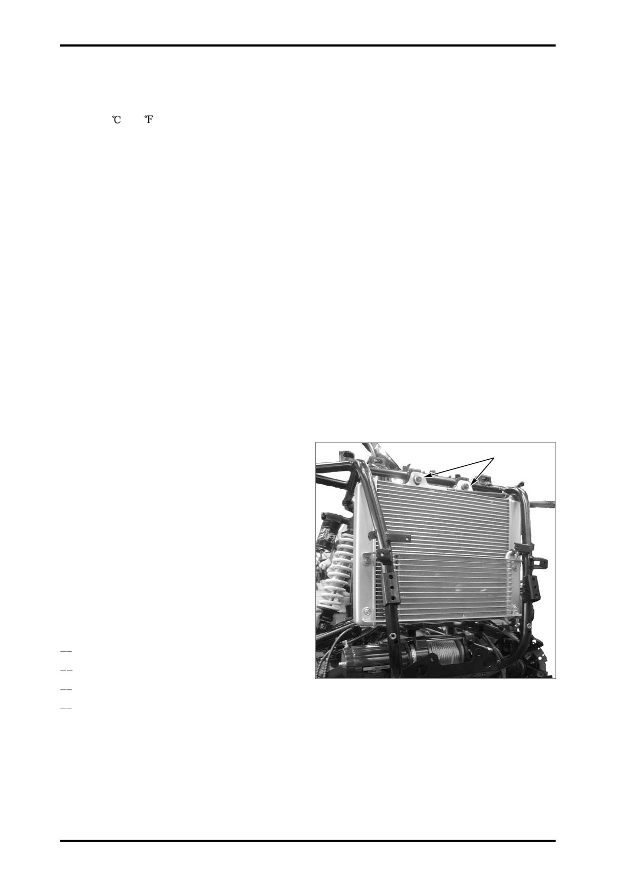
RADIATOR
Radiator Inspection
Check radiator fins for clogging or damage.Remove
insects,mud or other obstructions with compressed
air or low pressure water.
Radiator Removal
Drain cooling system
Remove front facia and radiator shroud,refer to VE-
HICLE BODY AND MUFFLER.
Remove:
RH inner fender
radiator mounting bolts
overflow hose
support and reservoir tank
1.Radiator Mounting Bolts
Unplug radiator fan.
Remove radiator.
04-8

04 COOLING SYSTEM
Radiator Installation
Reverse the removal procedure for installation.Pay at-
tention to the following details.
RESERVOIR TANK
2
The coolant expands as the temperature (up to 100 to
110
212 to 230
)) and pressure rise in the system.
If the limiting system working pressure cap is reached
110kPa(16PSI),the pressure relief valve in the tempera-
1
ture cap is lifted from its seat and allows coolant to
flow through the overflow hose into the reservoir tank.
Ensure ventilation holes are not obstructed.
Removal
Remove:
1.Reservoir Tank
2.Overflow Hose
RH inner fender(refer to VEHICLE BODY AND
MUFFLER).
coolant support bolt
overflow hose
support and reservoir tank
Empty coolant tank.
Installation
1
Reverse the removal procedure for installation.
COOLANT TEMPERATURE SENSOR
2
(CTS)
1.Bolt
Refer to ELECTRICAL SYSTEM for inspection and
2.Reservoir Tank
renewal process of CTS.
04-9
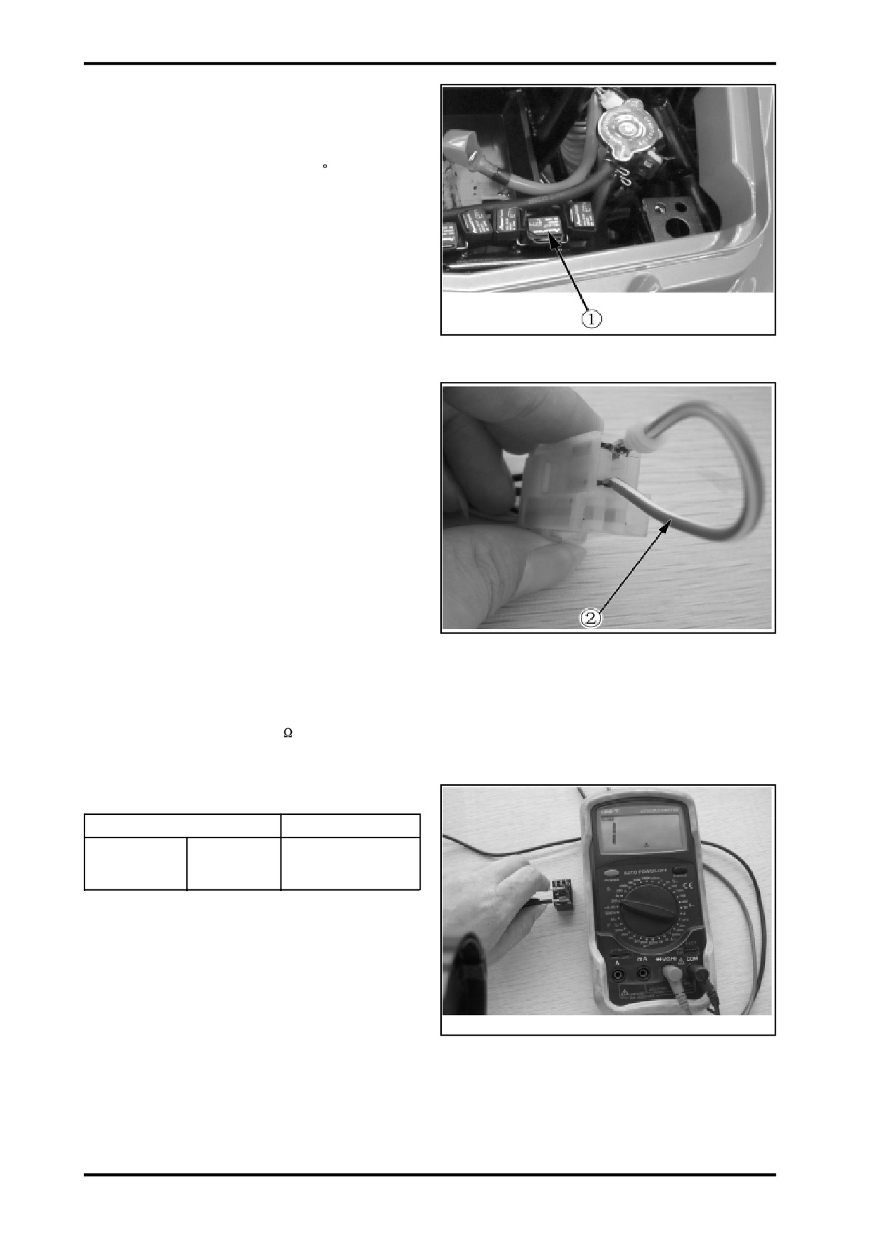
RADIATOR FAN RELAY
Installation
NOTE:Relay may be inverted by 180
at installation
and it will work correctly.Ensure to align tabs of relay
with terminals of fuse holder at installation.
1.Radiator Fan Relay
Relay Operation Test
The easiest way to check the relay is to remove it and
bypass it with a jumper.If the radiator fan is activated,
replace the relay.See illustration to find where to by-
pass the relay.
2. Bypass the Relay
Relay Continuity Test
Remove relay.
Use multimeter and select the position.
Probe relay as follows.
Terminals
Resistance
Open circuit
30
87
(0L)
3.Probe Relay
04-10

04 COOLING SYSTEM
Connect battery as follows.
Terminals
Resistance
0.5
max.
30
87
(continuous)
If relay fails any test,replace it.
RADIATOR FAN
Operation
The thermal switch controls the radiator operation.
Radiator fan should turn on when coolant tempera-
ture reaches 88
(190.4
) and should turn off when
4.Connect Battery
the coolant cools down at 84
(183.2
).
Radiator Fan Test
If radiator fan doesn’t turn on when the coolant tem-
perature exceeds 88
(190.4
),use the following
troubleshooting chart to resolve the problem.
04-11
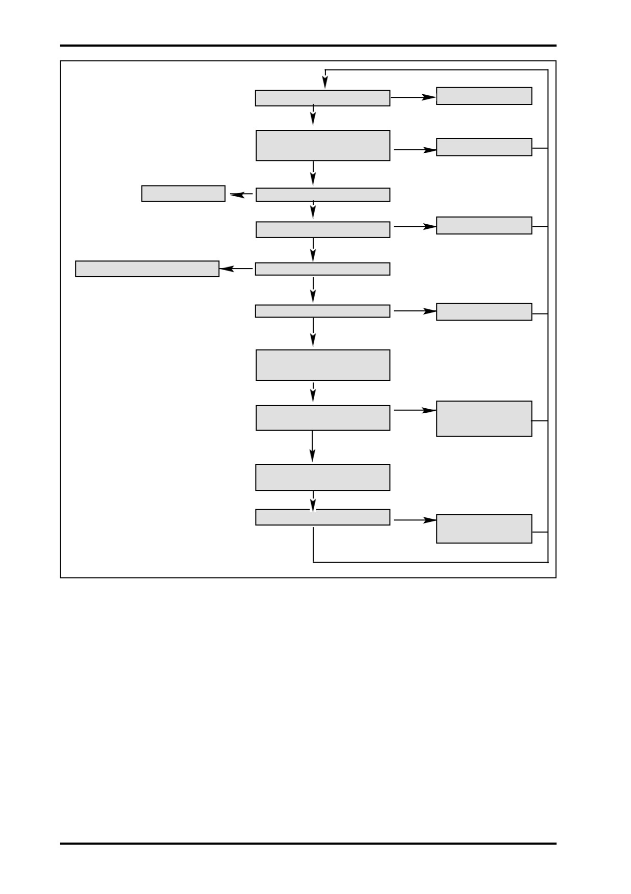
Yes
Is fan working?
Everything is ok
No
Check accessories fuse(30A) and
Yes
Replace fuse(s)
fan fuse(20A).Is fuse burned?
No
Bypass the relay
Check relay 1
Yes
Fan turns?
Replace relay
No
Apply 12 volts on fan connector
Check fan
No
Fan turns?
Replace fan
Yes
Check thermal switch
No
Thermal switch works?
Replace CTS
Yes
Check wiring harness
and connectors
No
All work well?
Repair or replace de-
Yes
fective part(s)
Removal
Remove radiator shroud.
Remove the bolts.
Remove the radiator fan.
Installation
Reverse the removal procedure for installation.
WATER PUMP HOUSING
It’s located on the engine MAG side.
04-12

04 COOLING SYSTEM
Removal
WARNING
To avoid potential burns,don’t remove the radia-
tor cap or loosen the cooling drain plug if the
3
engine is hot.
Drain the cooling system.
3
Remove outlet hose from water pump housing.
Remove screws retaining water pump housing.
Pull water pump to remove it.
4
2
1
1.Cooling Drain Plug
2.Sealing ring
3.Screws
4.Water Pump Housing
Inspection
Check if gasket is brittle,hard or damaged and replace
as necessary.
1
Installation
Reverse the removal procedure for installation.
CAUTION:To prevent leaking,take care that
the gasket is exactly in groove when you
reinstall the water pump housing.
Tighten screws of water pump housing in a
criss cross sequence.
1.Gasket
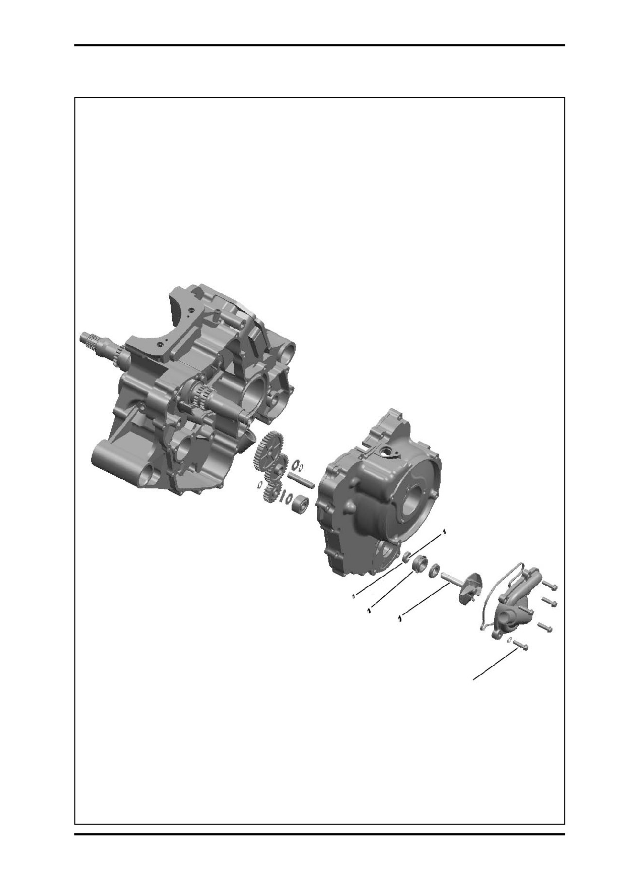
WATER PUMP IMPELLER,GEARS,
SEALS,SHAFT
2
Removal
Drain cooling system.Refer to this chapter.
Empty engine oil.Refer to LUBRICATION SYSTEM.
Remove water pump housing.Refer to this chapter.
Remove the crankcase cover,MAG side.Refer to
1
crankcase.
Remove the water pump intermediate gear and breather
shaft.
1.Intermediate Gear,Water Pump
2.Breather Shaft
04-13

Using appropriate pliers,remove and discard the re-
taining ring securing water pump gear on water pump
shaft.
Remove water pump gear.
3
Remove needle pin and gasket of water pump shaft.
2
1
1.Water Pump Impeller Assembly
2.Gasket
3.Needle Pin
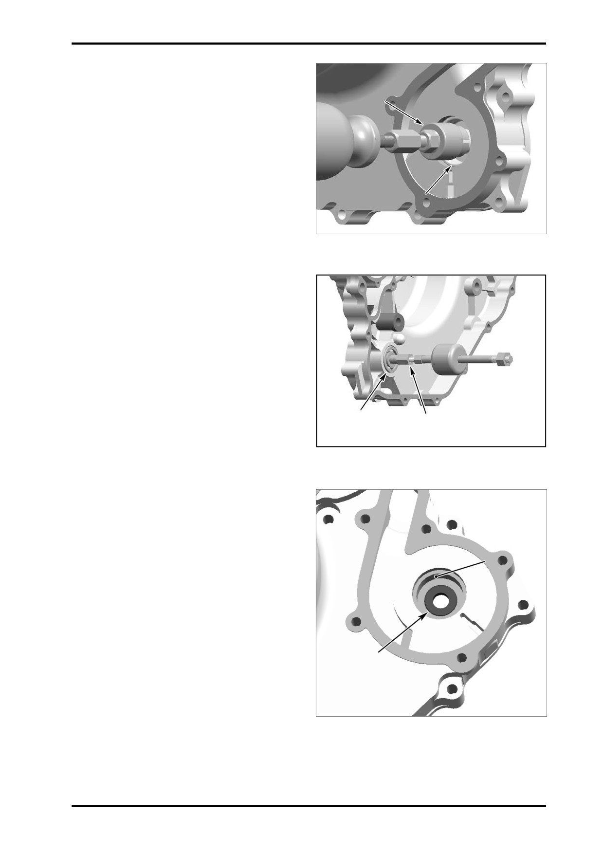
To remove water pump impeller assembly from left
crankcase cover, briskly tap the water pump shaft end.
1
CAUTION:Take care not to damage impeller
wings during installation.
Using an appropriate slotted screwdriver,pry out the
rotary seal.
2
1.Slotted Screwdriver
2.Rotary Seal
Using 2 slotted screwdrivers ,remove outer part of wa-
ter pump stationary seal.
2
1
1.Stationary Seal,Water Pump
2.Slotted Screwdrivers
04-14
04 COOLING SYSTEM
Using an puller,remove outer part of rotary seal.
Install puller snugly against outer part and pull rotary
seal out.
2
1
1.Inner Part,Stationary Seal
2.Seal Puller
Using a bearing puller(P/N:0800-014001-922-001 ),re-
move water pump bearing(If it’s necessary to replace
the water pump bearing).
1
2
1.Bearing
2.Bearing Puller
Remove oil seal.
2
1
1.Oil seal
2.Stationary Seal Surface
04-15
CAUTION:
Be careful not to damage the rotary seal surface.
Inspection
Check impeller for cracks or other damages.Replace
1
impeller if damaged.
Inspect water pump intermediate gear and water pump
gear for cracks,wear and other damages(especially
on the snap mechanism to the needle pin).Replace if
necessary.
Turn the bearing inner ring by hand. The bearing should
run smoothly,peacefully.If it’s stuck or has noise or
other defects,replace it.
Installation
1.Bearing
For installation,reverse the removal procedure.However,
pay attention to the following.
NOTE:For installation,use the torque values in the
exploded view.Ensure to apply engine oil on
intermeadiate shaft,water pump shaft and oil seal in-
ner surface.Don’t use oil in the press fit area of the oil
seal abd rotary seal.
CAUTION:Always replace rotary seal and
stationary seal at the same time.Meanwhile,
install a new oil seal(behind the rotary seal).
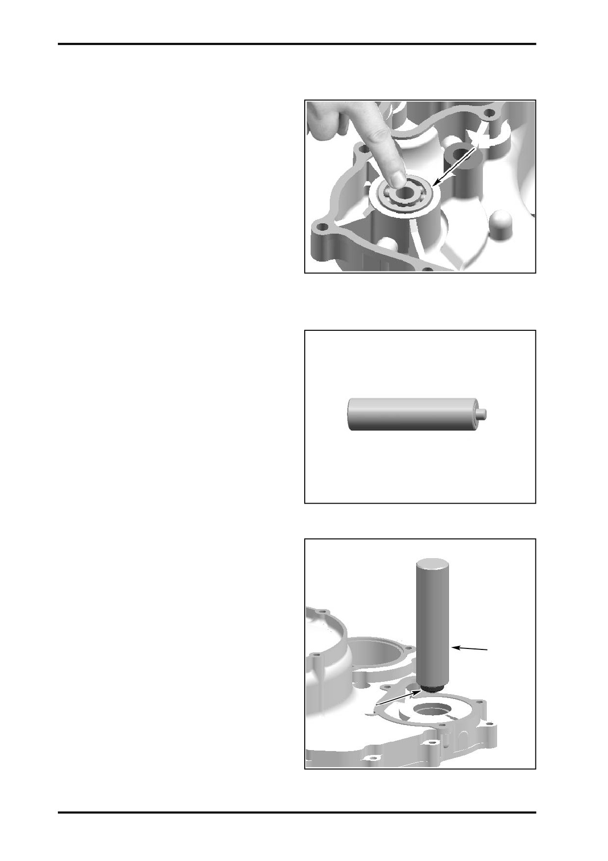
Use the oil seal pusher(P/N 0110-080005-923-001) to
Seal Pusher
install oil seal.
Apply oil on oil seal lip.
When installing the oil seal on the pusher,make sure
sealing lip poits outside.
Using oil seal pusher,install the oil seal in place.
2
1
1.Oil seal
2.Seal Pusher
04-16
04 COOLING SYSTEM
Place appropriate cushion blocks under the crankcase
cover to keep it level.
Using bearing pusher to push the bearing into left crank-
case press fit area.
NOTE:The left crankcase cover may be damaged if
3
no appropriate cushion bolks placed under it.
2
1
1.Bearing
2.Crankcase Cover,MAG Side
3.Bearing Pusher
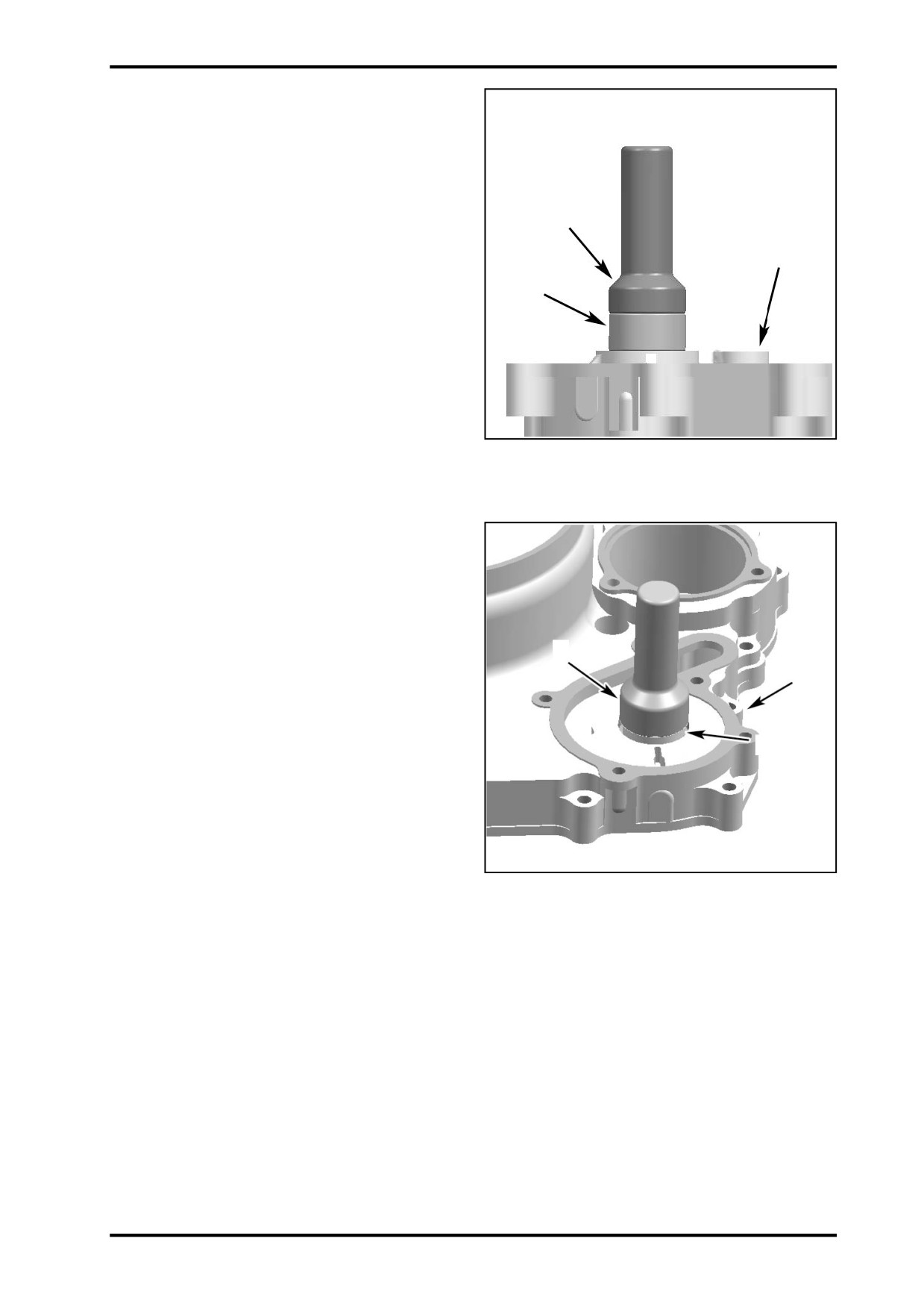
Apply loctite(silicone sealant) on stationary seal
surface.
Gently tap the seal pusher to install stationary seal in
place.
3
2
1
1.Stationary Seal,Water Pump
2.Crankcase Cover,MAG Side
3.Seal Pusher
04-17

Install the water pump impeller assembly with rotary
seal into left crankcase cover.
NOTE:Before water pump impeller installation,
clean the rotary seal and stationary seal surface,or
2
water may enter the crankcase.
1
1.Water pump Impeller Assembly
2.Left(MAG Side) Crankcase Cover
Install thrust washer on water pump shaft.
Push impeller by hand to fully expose shaft hole that
needle pin can be installed.
Install pin and position it at equal distance out of shaft
3
hole so water pump gear can be installed.
2
1
1.Water Pump Impeller Assembly
2.Gasket
3.Needle Pin
Align the water pump gear groove with needle pin,then
install water pump gear on the shaft.
2
Make sure gear properly snaps on pin.
1
Install a new retaining ring on pump shaft end.
1.Needle Pin
2.Water Pump Gear
04-18

04 COOLING SYSTEM
Install water pump intermediate shaft and ensure its
end with chamfer points outside.
1
Install water pump intermediate gear on shaft.
For remaining parts installation,reverse their removal
procedure.
Assemble the other parts base on reverse sequence
of removal.
Refill all fluids,including coolant and engine oil.
2
1.Breather Shaft
2.Intermediate Gear,Water Pump
04-19
5 ENGINE REMOVAL AND INSTALLATION
Maintenance Information
5-1
Differential and gearcase removal and installation...5-6
Engine removal and installation
5-2
Gearshift linkage removal and installation
5-8
5
MAINTENANCE INFORMATION
Operation Cautions:
z When performing engine removal and installation,use jack or other appropriate tools to securely support the
vehicle.Take care not to damage the engine,bolts and cables.
z Wrap the frame in appropriate areas where might be scratched to avoid damage during removal and installation.
z It’s not necessary to remove the engine when servicing the following parts:
5
-oil pump.
-throttle body,air filter.
-valve cover,cylinder head ,cylinder,camshaft.
-CVT system,CVT cover.
-magneto cover,AC magneto,water pump
-piston,piston ring ,piston pin
-front differential,rear gearcase
z It’s necessary to remove engine when servicing the following parts:
-crankshaft
-transmission.
Tightening Torque:
Engine mounting bolts (upper)
GB5789 M8X35
(35-45)Nz m
Engine mounting bracket bolts (upper)
GB5789 M10X1.5X20
(40-50)Nz m
Engine mounting bolts (front left)
GB5789 M10X1.25X125
(40-50)Nz m
Engine mounting bolts (front right)
GB5789 M10X1.25X100
(40-50)Nz m
Engine mounting bracket bolts (rear)
GB5789 M8X20
(35-45)Nz m
Engine mounting bolts (rear)
GB5789 M10X1.25X170
(40-50)Nz m
Engine mounting bracket bolts (rear)
GB5789 M8X20
(35-45)Nz m
5-1

ENGINE REMOVAL
Remove plastics ( VEHICLE BODY AND
MUFFLER,Chapter 2);
Remove air filter ( AIR INTAKE system);
Remove throttle body( ELECTRICAL SYSTEM);
Drain coolant;
Drain engine oil;
Remove hose clamp no.2;
Remove coolant inlet hose no.1;
Remove hose clamp no. 4;
Remove coolant outlet hose no.3;
Remove hose clamp no.5;
Remove engine external oil pipe no.6;
Disconnect magneto connector,CPS connector,cool-
ant temperature sensor connector,gear position sen-
sor connector,TPS connector,idle air control valve
connector,high pressure fuel line and throttle cable,
etc;
Remove muffler( VEHICLE BODY AND
MUFFLER,Chapter 2);
5-2

5 ENGINE REMOVAL AND INSTALLATION
Remove spark plug cap no.1 from cylinder 1(front);
5
Remove spark plug cap no.2 from cylinder 2(rear);
Take starter motor positive terminal sleeve off.Remove
the nut and starter motor positive cable no.3;
Remove the bolt and negative cable no.4 of starter
motor;
5-3

Remove the 4 bolts no.1 to disconnect front propshaft
from engine;
Remove the 4 bolts no.3 to disconnect rear propshaft
from engine;
Remove CVT inlet hose clamp no.5;
Remove CVT inlet hose no.6;
Remove CVT outlet hose clamp no.7;
Remove CVT outlet hose no.8;
5-4

5 ENGINE REMOVAL AND INSTALLATION
Remove bolt no.1 to disconnect shifting plate no.2 from
engine;
Remove engine mounting bolts (front left)&(front right)
5
no.4;
Remove engine mounting bolts(rear) no.3;
Remove engine mounting bolts(upper) no.5;
5-5
ENGINE INSTALLATION
After placing engine on the vehicle,install engine mount-
ing bolts and nuts (front left) first,then (front right) and
(rear).
Install engine inlet/outlet coolant hoses/oil pipes by
clamps onto the engine.Connect starter motor posi-
tive/negative cables.
Connect all connectors.Install CVT breather duct,spark
plus cap.Install shifting plate,air filter,throttle body and
other removed parts.
FRONT/REAR GEARCASE REMOVAL
AND INSTALLATION
Removal
Raise the vehicle off ground with jack.Ensure the ve-
hicle would not tip or fall.
Remove plastics
(
VEHICLE BODY AND
MUFFLER,Chapter 2);
Remove front/rear wheels and A-arms.
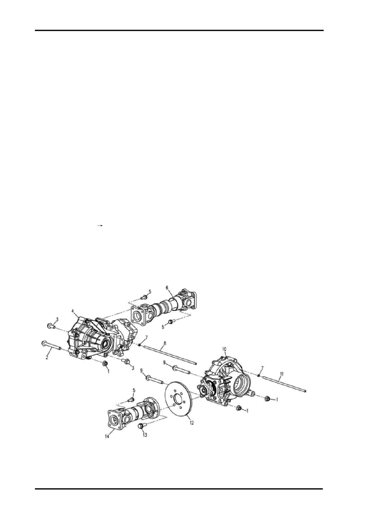
1.Nut 2.Bolt#1 3.Blt#2 4.Front Differential 5.Bolt#3 6.Front Propshaft 7.Clamp
8 . Front Differential Breather Hose
9.Bolt#4 10.Rear Gearcase 11.Rear Gearcase Breather Hose
12.Rear Brake Disc 13.Bolt#5 14.Rear Propshaft
5-6
5 ENGINE REMOVAL AND INSTALLATION
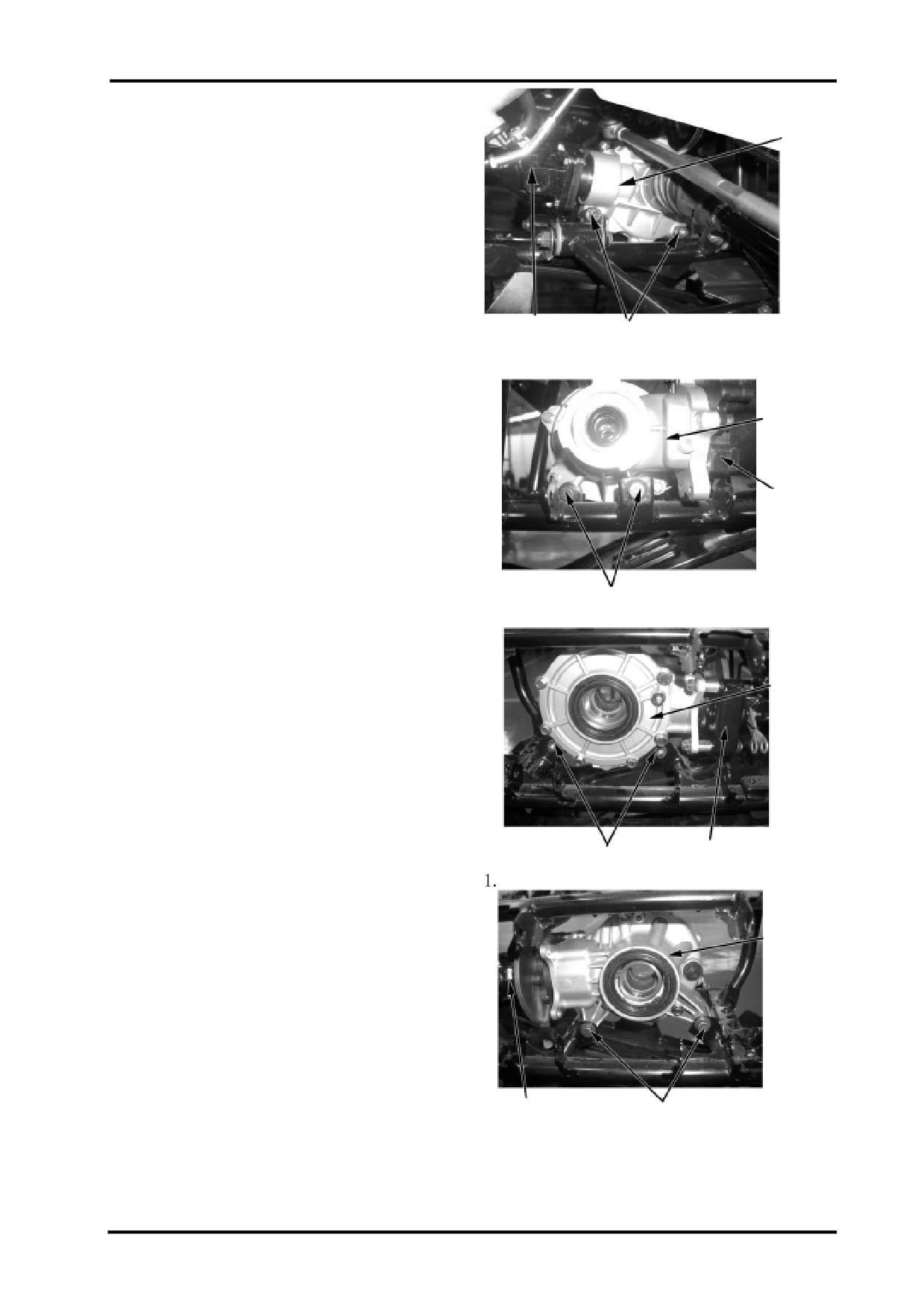
Remove front differential mounting bolts & nuts;
①
③
②
1.Front Differential 2.Bolts 3.Front Propshaft
①
5
③
②
1.Front Differential
2.Bolts 3.Front Propshaft
①
Remove rear gearcase mounting bolts & nuts ;
③
②
Rear Gearcase 2.Bolts 3.Rear Propshaft
①
③
②
5-7

Remove the 18 bolts which connect propshafts and
gearcases(see 5,bolt 3);
Remove propshafts,gearcases,and brake discs.
Installation
Reverse the removal procedure for installation.
Tightening Torque:
Front differential mounting bolt :40-50Nz m
Rear gearcase mounting bolt :40-50Nz m
①
Front and rear propshaft bolt :40-50Nz m
1.Propshaft Bolts
GEARSHIFT LINKAGE
Removal
Remove passenger seat(
2-4);
Remove driver seat(
2-4);
Remove air filter cover(
2-5);
Remove left side panel (
2-6);
Remove gearshift lever knob(
2-6);
Remove gearshift lever indicator(
2-6);
Remove bolt no.2 and shifting plate;
Loosen gearshift rod adjustment nuts no.1,remove
gearshift rod;
Remove gearshift locking cable no.5;
Remove the 3 bolts of gearshift bracket and then re-
move the linkage.
Installation
Reverse the removal procedure for installation.
After installation,check gearshift linkage for smooth-
ness and agility.If gearshifting sticks,adjust nuts no.1
to change the length of gearshift rod.
5-8
06 AIR INTAKE SYESTEM
AIR INTAKE SYSTEM
SERVICE PRODUCTS
6
Description
Part Number
Page
Air Filter Cleaning Solution
03
06-1
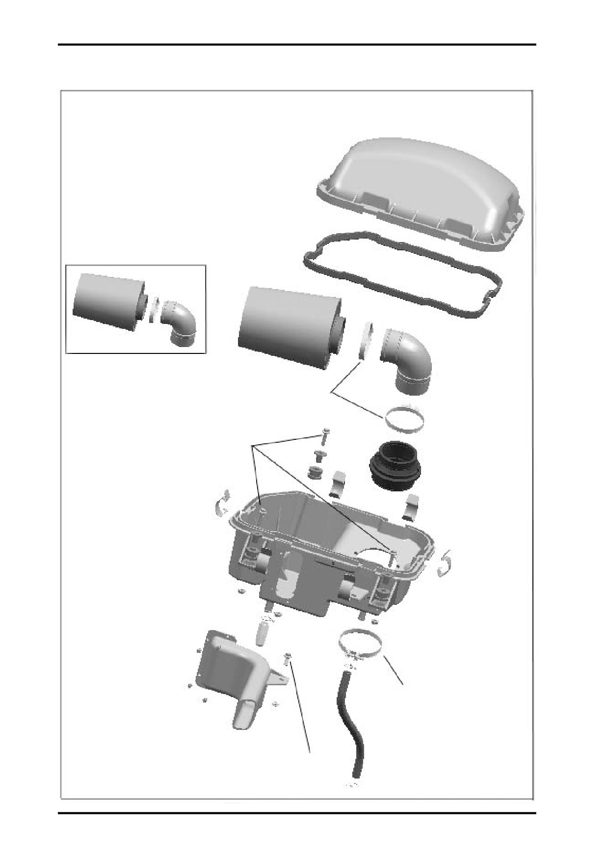
AIR FILTER HOUSING
2.5 N.m(22 lbf.in)
10 N.m(89 lbf.in)
2.5 N.m(22 lbf.in)
6 N.m(53 lbf.in)
06-2
06 AIR INTAKE SYESTEM
GENERAL
During assembly/installation, use the torque values
and service products as in the exploded views.Clean
threads before applying a threadlocker.Refer to LU-
BRICANTS AND SERVICE PRODUCTS at the be-
ginning of this manual for complete procedure.
WARNING
Torque wrench must be used when tightening.
Locking devices(e.g.:locking tabs,elastic
stop nuts, cotter pin,etc.) must be replaced
with new ones.
1
PROCEDURES
2
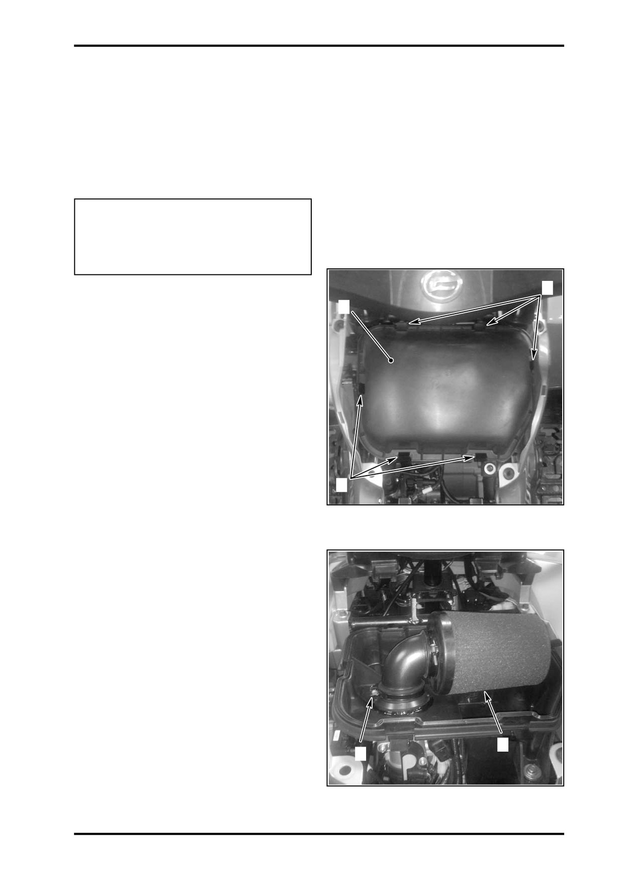
AIR FILTER
Air Filter Removal
CAUTION: Never remove or modify any compo-
nent in the air filter housing. The engine manage-
ment system is calibrated to operate specifically
with these components. Otherwise, engine perfor-
mance degradation or damage can occur.
Remove passenger seat,driver seat. Refer to VEHICLE
BODY AND MUFFLER.
Release clamps and remove air filter cover.
1
1.Clamps
Loosen clamps and remove air filter housing(upper).
2.Air Filter Housing
NOTE: If vehicle is used in dusty area,inspect more
frequently than specified in MAINTENANCE CHART.
If lilquid/deposits are found, squeeze and dry the foam
filter. Replace filter element if damaged.
CAUTION: Do not start engine if liquid or deposit
are found. If there is oil in the air filter housing,
check engine oil level. Oil level may be too high.
Pour air filter cleaning solution or an equivalent into a
bucket. Put the foam filter in to soak. Do not wash
filter element.
2
While filter soaks, clean inside of air filter housing.
1
1.Clamp
2.Air Filter
06-3

Rinse foam filter with warm water and let it dry
completely.
Blow low pressure compressed air on filter element to
clean it.
Air Filter Installation
Properly reinstall removed parts in the reverse order of
their removal.
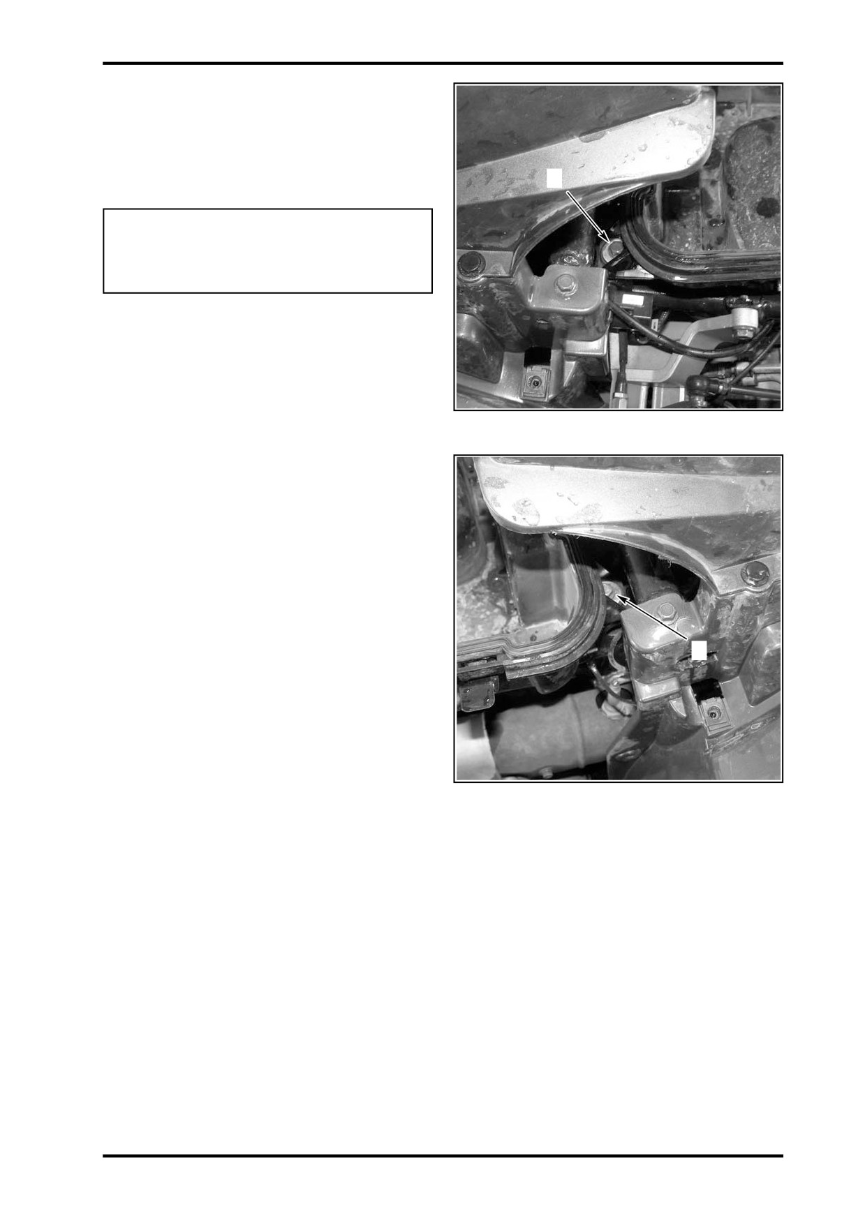
AIR FILTER HOUSING
Air Filter Housing Removal
Remove seat, side panels;
Refer to VEHICLE BODY AND MUFFLER;
2
Loosen clamp and hose tie;
Disconnect breather hose;
3
1
1.Clamp
2.Hose Tie
3.Breather Hose
Remove air filter housing mounting bolts;
1
1.Bolt
06-4
06 AIR INTAKE SYESTEM
Pull air filter housing out.
Air Filter Housing Installation
1
Reverse the removal procedure for installation.
WARNING
Depress throttle lever several times to ensure
it properly returns.
1.Bolt
1
1.Bolt
06-5
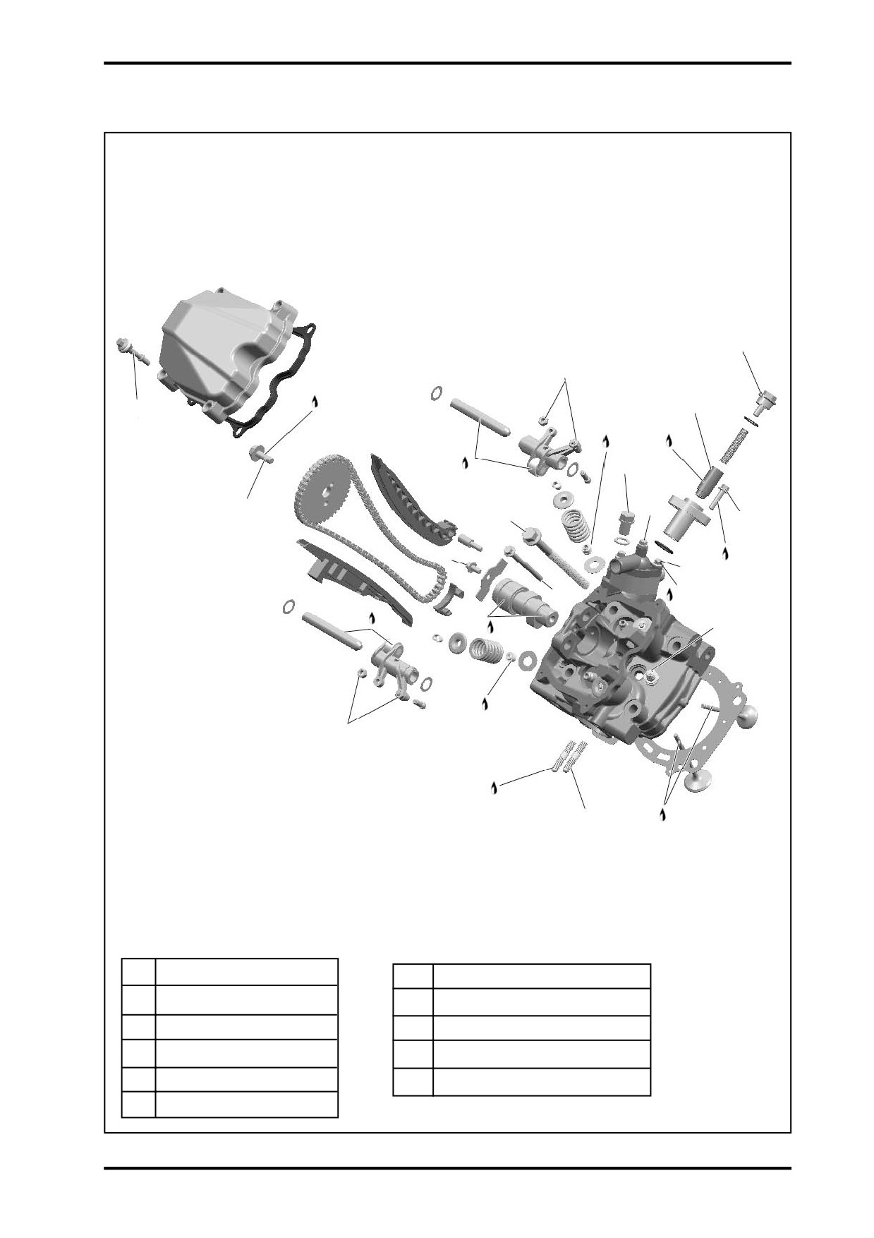
07 INTAKE MANIFOLD, CYLINDER HEAD AND CYLINDER
INTAKE MANIFOLD,CYLINDER HEAD AND CYLINDER
7
SERVICE TOOLS
Description
P/N
Page
Spark plug spacer
0800-022800-922-001
07
Camshaft locking tool
0800-024001-922-001
09
Crankshaft locking bolt
0800-041000-922-001
27
Valve spring compressor clamp
0180-022006-922-001
32
Valve guide remover
0800-022102-922-001
37
Valve guide installer
0800-022102-922-002
38
Piston ring compressor
0800-040003-922-001
41
Piston pin circlip installer
0800-040005-922-001
45
SERVICE PRODUCTS
Description
P/N
Page
Coolant
Engine oil
Loctite
38
07-1

INTAKE MANIFOLD
0.5 N.m(5 lbf.in)
6 N.m(53 lbf.in)
Threadlocker
6 N.m(53 lbf.in)
Engine Oil
Threadlocker
0.5 N.m(5 lbf.in)
6 N.m(53 lbf.in)
Engine Oil
Threadlocker
Engine Oil
20 N.m(15 lbf.ft)
07-2
07 INTAKE MANIFOLD, CYLINDER HEAD AND CYLINDER
CYLINDER HEAD I
T8
T4
Threadlocker
T9
Engine Oil
T6
Engine Oil
Engine Oil
T3
T1See
T2
Procedure
T11
T7
Inside
T5
T7
Threadlocker
T5
Threadlocker
Engine Oil
Engine Oil
T3
Engine Oil
T4
Threadlocker
T5
Engine Oil
T1
60N.m (44 lbf.ft)
T7
6N.m (53 lbf.in)
T2
30N.m (22 lbf.ft)
T8
4.5N.m (40 lbf.in)
T3
20N.m (15 lbf.ft)
T9
0.1N.m (0.89 lbf.in)
T4
12N.m (106 lbf.in)
T10
16N.m (141 lbf.in)
T5
10N.m (89 lbf.in)
T11
5N.m (44 lbf.in)
T6
7N.m (62 lbf.in)
07-3
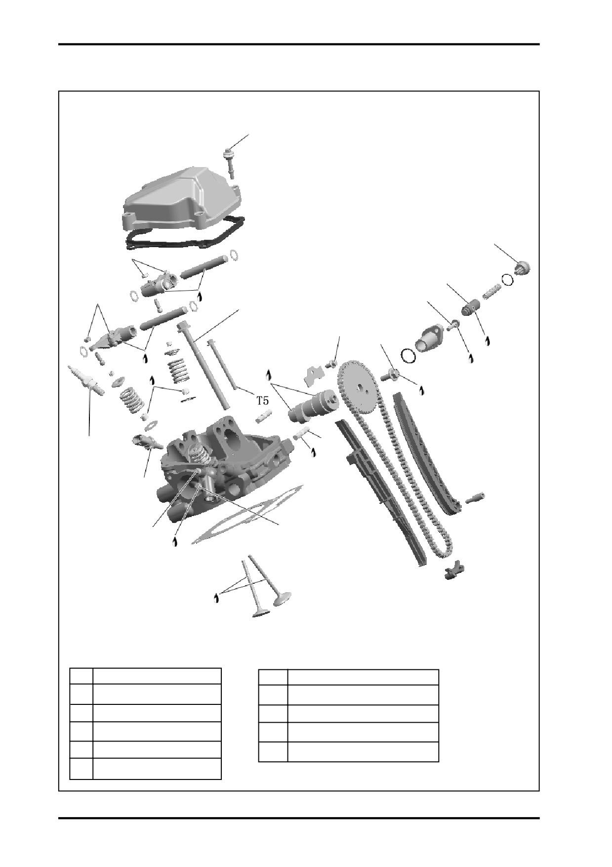
CYLINDER HEAD II
T6
T8
T4
T9
Engine
T4
T 1 S e e
T7
Oil
Procedure
Inside
T5
T2
Engine Oil
Engine Oil
Engine Oil
Threadlocker
Threadlocker
T3
T5
Threadlocker
T10
T7
T11
Threadlocker
Engine Oil
T1
60N.m (44 lbf.ft)
T7
6N.m (53 lbf.in)
T2
30N.m (22 lbf.ft)
T8
4.5N.m (40 lbf.in)
T3
20N.m (15 lbf.ft)
T9
0.1N.m (0.89 lbf.in)
T4
12N.m (106 lbf.in)
T10
16N.m (141 lbf.in)
T5
10N.m (89 lbf.in)
T11
5N.m (44 lbf.in)
T6
7N.m (62 lbf.in)
07-4

07 INTAKE MANIFOLD, CYLINDER HEAD AND CYLINDER
CYLINDERS AND PISTONS
Engine Oil
Engine Oil
Engine Oil
Engine Oil
Engine Oil
07-5
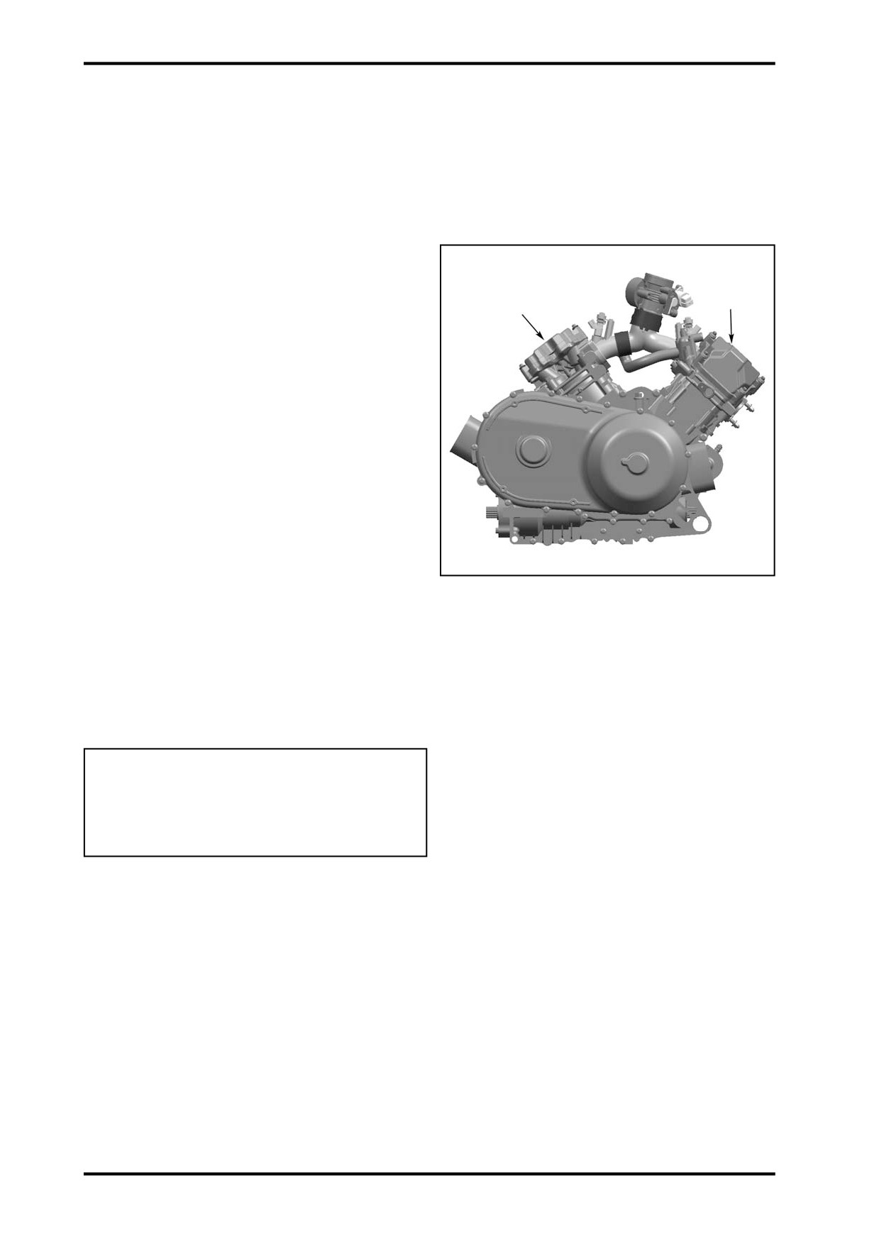
GENERAL
Components which are identical for both cylinders/
cylinder heads are identified in the two exploded views
by the same number. Components which are different
or which are, for instance, present of one of the cylin-
ders/cylinder heads but not on the other, have differ-
ent numbers. The information given below always re-
lates as a genaral rule.
Special reference is made in the text to work instruc-
1
2
tions which are not the same for cylinder no. 1 and
cylinder no.2.
When diagnosing an engine problem, always diagnose
cylinder 1 and 2 respectively.
Always place the vehicle on a level surface.
NOTE: For a better understanding, the many illus-
trations are taken with engine out of vehicle. To per-
form the following instructions if it is not necessary to
remove engine from vehicle.
Always disconnect BLACK(-) cable from the battery,
then RED(+) cable before working on the engine.
Even if the removal of many parts is not necessary to
reach another part, it is recommended to remove these
1.Cylinder 1 (Front)
parts in order to check them.
2.Cylinder 2 (Rear)
During assembly/installation, use the torque values
and service products as in exploded views.
Clean threads before applying a threadlocker.Refer to
LUBRICANTS AND SERVICE PRODUCTS at the be-
ginning of this manual for complete procedure.
WARNING
Torque wrench must be used when tightening.
Locking devices(e.g.: locking tabs, elastic stop
nuts,cotter pin,etc.)must be replaced with new
ones.
When disassembling parts that are duplicated in the
engine,(e.g.: values), it is strongly recommended to
note their position(PTO/MAG side, front/rear cylinder)
and to keep them as a “group”. If you find a defective
component, it would be much easier to find the cause
of the failure among its group of parts(e.g.: you found
a worn valve guide. A bent spring could be the cause
and it will be easy to know which one among the
springs is the cause to replace it if you grouped them
at disassembly). Also, since used parts have matched
together during the engine operation, they will keep
their matched fit when you reassemble them together
within their “group”.
07-6
07 INTAKE MANIFOLD, CYLINDER HEAD AND CYLINDER
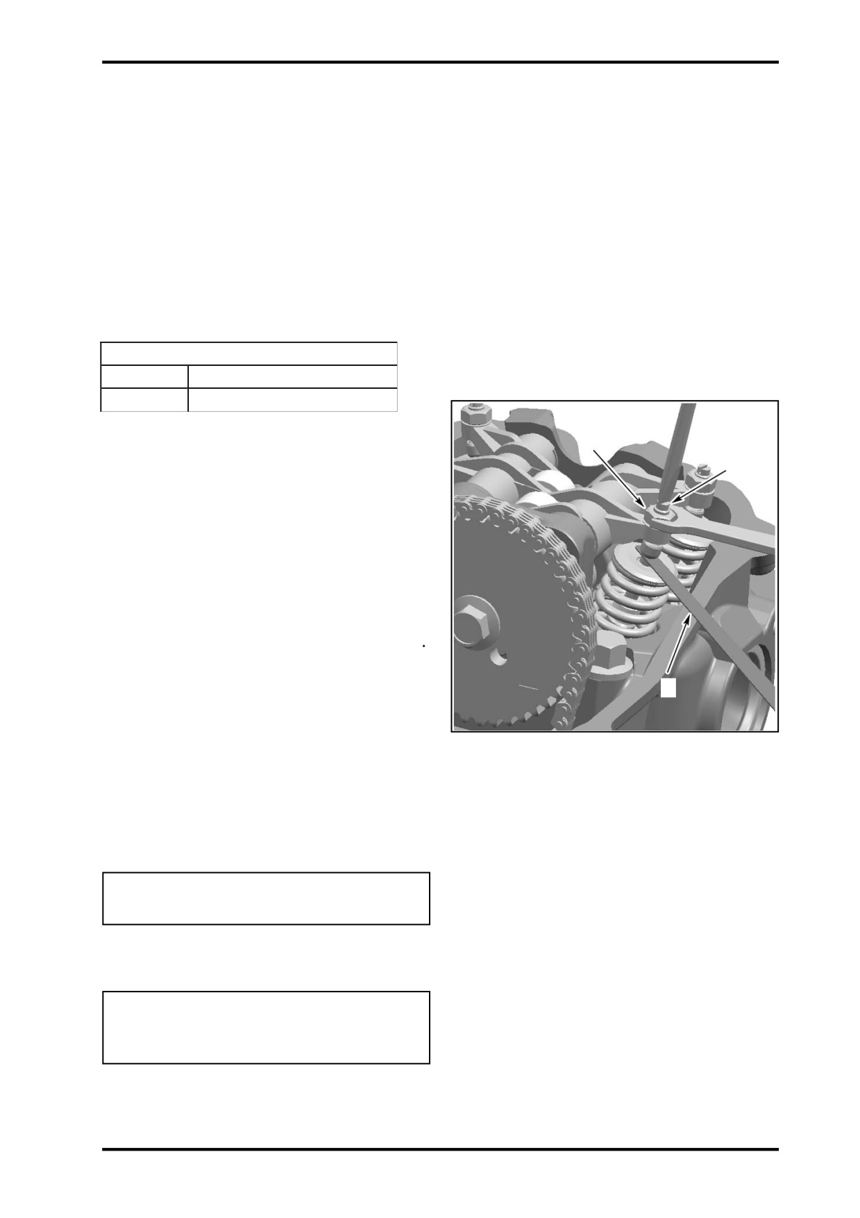
MAINTENANCE
VALVE ADJUSTMENT
NOTE: Check and adjust valve clearance only when
engine is cold.
Remove valve cover.
Before checking or adjusting the valve clearance, turn
crankshaft to TDC ignition of the respective cylinder,
see CAMSHAFT.
Use feeler gauge to check the valve clearance.
Valve Clearance
Exhaust
0.11-0.19mm(0.0043-0.0075in)
Intake
0.06-0.14mm(0.0024-0.0055in)
2
1
If the valve clearance is out of specification, adjust
valves as folows.
NOTE: Use mean valve of exhaust/intake to ensure a
proper valve adjustment.
Hold the adjustment screw at the proper position and
torque the locking nut.
Repeat the procedure for each valve.
Before installing valve cover, recheck valve clearance
INSPECTION
3
LEAK TEST
Before performing the cylinder leak test, verify the
1.Adjustment Screw
following:
2.Locking Nut
-clamp(s) tightness
3.Feeler Gauge
-radiator and hoses
NOTE: For best accuracy, the leak test should be
done with the engine at normal operating temperature.
WARNING
Prevent burning yourself on hot engine parts.
Preparation
Disconnect battery
WARNING
Always respect this order for disassembly;
disconnect BLACK(-)cable first.
Remove radiactor cap.
07-7