CFMoto ATV Terralander CF800-2. Service Manual - part 1

Unit Conversion Table
Item
Example
Conversion
Pressure
200kPa(2.00kgf/cm²)33kPa(250mmHg)
1 kgf/cm2=98.0665kPa 1kPa=1000Pa
1mmHg=133.322Pa=0.133322kPs
Torque
18N· m(1.8kgf· m)
1 kgf· m=9.80665N· m
Volume
419ml(419cm3,419cc) 419ml(0.419l)
1 ml=1 cm3=1 cc 1l=1000 cm3
Force
12N(1.2kgf)
1 kgf=9.80665N
1 GENERAL INFORMATION
Maintenance information………… .…1-1
Tightening torque table……………1-13
Location of VIN/EIN ……… ……… …1-3
L ubricants and service products…1-19
General specifications……… ……… 1-4
W iring,pipes&cables ……… …… …1-20
Maint enanc e specificat ions… ……1-6
MIL/ EVAP system… …………… …….24
1
MAINTENANCE INFORMATION
Operation cautions
1. Engine exhaust fumes are poisonous and can result in loss of consciousness or death. Do not run the
engine in an enclosed or poorly ventilated area.
2. Do not touch the engine or muffler with bare hands after the engine has been just stopped to avoid burns.
Wear long-sleeve work clothes and gloves for operation.
3. Battery electrolyte (dilute sulfuric acid) is highly caustic and can result in burns from contact with skin and
eyes. If you spill electrolyte on skin,flush with water and seek for medical attention immediately. If you spill
electrolyte on clothes,flush with water if to avoid burns. Keep battery and electrolyte out of reach of children.
4. Coolant is poisonous. Do not drink or spill it on skin, eyes or clothes. If you spill coolant on skin,immediately
wash with soap and water. If you spill coolant on eyes, flush with water and seek prompt mediacal attention.
If you swallow coolant, induce vomit and see the doctor. Keep coolant out of reach of children.
5. Wear proper work clothes, cap and boots. If necessary, were dust-glass, gloves and mask.
6. Gasoline is highly flammable. No smoking or fire. Also keep gasoline away from sparks. Vaporized gasoline
is also explosive. Operate in a well-ventilated area.
7. When the battery is being charged, it produces explosive gases. Charge the battery in a well-ventilated area.
8. Be careful not to get pinched by the turning parts like wheels and clutch.
9. When more than two people are operating, keep reminding each other for safety purpose.
Cautions for removal and installation
1. Use genuine CFMOTO parts, lubricants and service products.
3. Clean mud, dust before servicing.
2. Store the removed components separately in order for correct installation.
4. Replace the removed washers, o-rings, piston pin retainers, cotter pins with new ones.
5. Elastic retainers might get distorted after disassembled. Do not use the loosened retainers.
6. Clean and blow off the detergent after removal. Apply lubricants on the surface of moving parts. Measure the
data during removal for correct installation.
7. If you do not know the length of screws, install the screws one by one and make sure they are screwed in
with the same depth.
8. Check if the removed rubber parts are aged and replace if necessary. Keep the rubber parts away from
grease.
9. Pre-tighten the bolts, nuts and screws, then torque to specification.The basic sequence is from big to small,
from inner side to outer side and criss-cross.
10.Replace aged rubber parts when assembling. Do not splash gasoline,grease onto the surface,as this
could cause damage.
1-1
11. Apply or inject recommended lubricant to the specified lubrication points.
12. Use special tools when necessary.
13. When ball bearing is removed by pressing steel balls, it can not be reused.
14. Finger turn the inner and outer rings of ball bearing to make sure the bearing will turn smoothly.
z
Replace if the axial or radial play is too big.
z If the surface is uneven, clean with oil and replace if the cleaning does not work.
z When pressing the bearing into the machine or onto the shaft,if the bearing can not be securely seated,
replace it.
15. Install the one-side dust-proof bearing in the right direction. When assembling the open type or double-side
dust-proof bearing, install with manufacturer’s mark outward.
16. Keep the bearing block still when blowing dry the bearing after washing clean. Apply oil or lubricant before
installation.
17. Install the elastic circlip properly. Turn the circlip after assembling to make sure is has been installed into
the slot.
18. After assembling, check if all the tightened parts are properly tightened and can move smoothly.
19. Brake fluid and coolant may damage painting, plastic and rubber parts. Flush with water if splashed on
thses parts.
20. Install oil seal with the side of manufacturer’s mark outward.
z Do not fold or scratch the oil seal lip.
z Apply grease to the oil seal lip before assembling
21. When installing pipes, insert the pipe till the end of joint. Fit the pipe clip, if any, into the groove. Replace
the pipes or hoses that cannot be tightened.
22. Do not mix mud or dust into engine and/or the hydraulic brake system.
23. Clean the gaskets and washers of the engine casing before assembling. Remove the scratches on the joint
faces by polishing evenly with an oilstone.
24. Do not twist or bend the cables too much. Distorted or damaged cables may cause poor
25. When assembling the parts of protection caps, insert the caps to the grooves, if any.
ENGINE BREAK-IN
There are many movable components inside the engine, such as piston, piston ring, cylinder, crankshaft,
gears and so on.During initial use period, proper run-in for every critical component is necessary.Break-in can
help engine components match each other better and adjust working condition.Careful treatment of a new
engine will result in more efficient performance and a longer service life.
Recommended break-in period: First 20 hours
Operation guide:
0~10 Hours
Do not operate continously at more than 50% throttle position.
Cool down the engine for every 5~10 minutes after every 1 hour operation.
Avoid sudden acceleration.Vary the throttle position slowly and smoothly.Do not vary the throttle position
rapidly.
10~20 Hours
Avoid long-time run at more than 75% throttle position. Do not open throttle completely during the period.
ATTENTION:
1.Maintain and repair as regular procedures during break-in period.
2.After break-in, do not forget to check and maintain the engine before normal use.
1-2
1 GENERAL INFORMATION
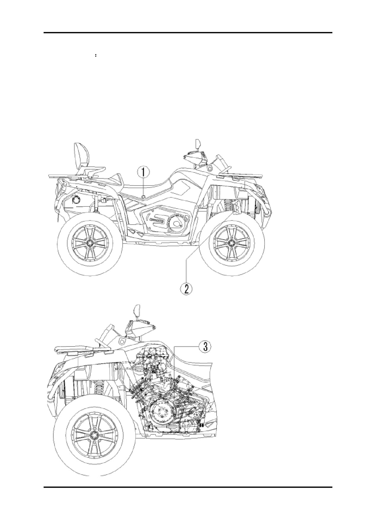
LOCATION OF VIN/EIN
Model Number CF800-2
1. Vehicle identification number(VIN): LCELVYZ3~
2. Name plate (Vehicle identification number label)
3. Engine identification number(EIN): 2V91W~
1-3
1 GENERAL INFORMATION
Item
Specifications
Model type
CF800-2
Overall length
2310mm
Overall width
1180mm
Overall height
1340mm
Wheelbase
1480mm
Engine type
2V91W
Displacement
800ml
Fuel type and Octane No.
RQ-93 or higher unleaded gasoline
Dry weight
400 kg
Passengers
2 persons (including driver)
Total vehicle load allowed
2persons +105 kg =255 kg
AT26×9—12 49J
Front
AT26×9—14 48J
Tire
AT26×11—12 55J
Rear
AT26×11—14 54J
Min. ground clearance
270mm
Min. turning radius
8000mm
Starting
Electric start
Type
V-twin cylinder,4-stroke,liquid-cooled,8 valves,SOHC
Valves
SOHC /Timing chain drive
Bore×Stroke
91mm×61. 5mm
Compression ratio
10.3:1
Engine
Lubrication
Wet sump, replaceable oil filter
Oil pump
Rotor drive
Oil filter
Paper type, replaceable
Engine oil type
SAE15W-40/SG or higher
Cooling system
Liquid-cooled/close-loop cooling
Coolant type
-30℃anti-corrosion and anti-freezing
1-4
1 GENERAL INFORMATION
Item
Specifications
Air filter type
Paper filter element
Air intake
Type
0800-173000
devices
Throttle body
Diameter of throttle body
48mm
Fuel tank capacity
23 L
Clutch type
Wet shoes and auto centrifugal
Transmission type
CVT+ Gearshift
Gearshift
High, Low and Reverse
Gearshift
Manual operation/L-H-N-R-P
methods/orders
CVT ratio range
2.88~0.70
“H” gear
“L” gear
“R” gear
Drive train
Final ratio
1.333
Gearshi
Secondary ratio
1.952
ft ratio
Single gear ratio
1.143
2.529
2.231
Total ratio
2.975
6.585
5.807
Front
33 / 9 = 3.667
Ratio of drive gear
Rear
33 / 9 = 3.667
Output type
Front/Rear shaft drive
Rotation of engine output
When forward, clockwise (rear view)
Left
31º
Steering
Turn angle
Right
31º
Front
Hydraulic Disc
Brakes
Rear
Hydraulic Disc
Suspension
Double A-arm and independent
Frame type
Steel tube and plate
1-11

MAINTENANCE SPECIFICATIONS
Lubrication System
Ite m
Standards
Service Limit
Oil Change
3400ml(without oil filter replacement)
-
Oil Change
3500ml(with oil filter replacement)
Engine OiL
Capacity
Oil Capacity
3600ml
-
Oil
I
600ml(Note:fill after first start)
and Hose s
20W-50
z
Recommended engine oil:SAE 15w40 API SG.If it’s not
15W-40,15W-50
available,select alternative according to the following
Grade
10W-40,10W-50
specifications.
10W-30
z
API classifications: SG or higher
5W-30
z
Viscosity rating: according to the left chart
-30 -20 -10 0 10
20 30 40
z
-22 -4
14 32 50 68
86 104
Clearance Between
I
0.06-0.14mm
0.25mm
and Outer Roto r
Clearance Between Oute r
0.09-0.15mm
0.25mm
Rotor and Bore
Oil Pump Rotor
Rotor End Clearance
0.023-0.109mm
0.20mm
1500rpm:70-300kPa(90 ),Typical:180kP a
Oil Pressure
6000rpm:350-550kPa(90),Typical:420kP a
Air Intake System
Ite m
Standards and Specifications
Fuel Tank
Total Capacity
23L
Throttle Body Part NO
0800-173000
T-MAP Sensor Part No .
0800-175000
Fuel
I
0800-171000
I
l
1300
100rpm
1-6

1 GENERAL INFORMATION
I tem
Sta nd a rd s
S e r v i c e l im i t
F ull c a p a ci t y
3 0 0 0ml
C a p a ci t y o f r e s e r v oi r
380~6 0 0ml
C o ol a n t c a p a ci t y
ta n k
Sta n d a rd d e n si t y
50%
O p e ni n g p r e s s u r e
1 0 8 k p a (1 . 1 k g f /cm 2 )
O p e ni n g
6 5±2℃
tempe ra tu re
F ull y o p e ni n g
85℃
Th e rm o s ta t
Tr a v el wh e n f ul l y
W h e n 85℃,>5mm
o p e ni n g
W a te r
Resistant of B
Resistant of A,C
tempe ra tu re(℃)
terminal(Ω)
terminal(kΩ)
R el a ti o n sb e t we e n
-20
----
2 8 .5 8 2±0 .0 0 4
wa t e r t em p .an d r e si s ta n
t o f wa te r t em p . s e n s o r
25
-----
2 . 7 9 5±0 . 0 0 2 5
50
216.0-216.4
0.98±0 . 0 0 2 2 7
80
74.6-90.6
0 . 3 3 4±0 . 0 0 2 0 4
110
32-36
0 . 1 3 3±0 . 0 0 2 5 2
A r o u n d 8 8℃
A r o u n d 8 8℃
O F F - ON
W o rki n g tem p . o f
the rm o s wi tc h
A r o u n d 8 2℃
A r o u n d 8 2℃
ON - O F F
- 30℃ a n ti -f r e e zi n g , a n ti -c o r r o si ve a n d hi g h b oili n g p oi n t
C o ol a n t t y p e
1-7
1 GENERAL INFORMATION
Item
Standard value
Service limit
Longitude
1.0mm
2.0mm
Rim jump
Transverse
1.0mm
2.0mm
Front wheel
Remaining
3.0mm
Front tire
groove
Pressure
45kPa(0.45kgf/cm2)
Service
Item
Standard value
limit
Longitude
1.0mm
2.0mm
Rim jump
Transverse
1.0mm
2.0mm
Rear wheel
Remaining
3.0mm
Rear tire
groove
Pressure
45kPa(0.45kgf/cm2)
Item
Standard value
Service limit
Free play of brake lever
0mm
Front brake
Thickness of brake disc
3.5mm
2.5mm
Free play of brake lever
10-20 mm
Rear brake
Free play of brake pedal
0mm
Thickness of brake disc
7.5mm
6.5mm
1-8
1 GENERAL INFORMATION
Item
Standards
Type
Magneto 3-phase AC generator
Output
3-phase AC output
Resistance of coil(20℃)
0.2Ω-0.3Ω
Resistance of pick-up coil
250Ω-300Ω
AC Flywheel
Voltage without load(cold engine)
>100V(AC),5000r/min
Max. output power
350W,5000r/min
Stable voltage
13.5V-15.0V, 5000r/min
Peak voltage of pick-up
≥1.5V,200 r/min
3-phase supply
power
of
Regulator type
thyristor trigger circuit
Capacity
12V 30Ah
Voltage
Fully recharged
14.4V
between
Battery
Not-fully recharged
≤11.8V
terminals
Recharging
Standard
1A/5~10H
current/time
Quick
5A/1H
Item
Standards
Ignition type
ECU
Type
Resistant-type
Standard
DCPR8E
(NGK)
Spark plug
Gap of spark plug
0.8-0.9mm
Characteristic
>8mm,under 1Kpa
Ignition time
BTDC10º
1500r/min
Resistance
of
Primary
0.70Ω-0.75Ω
ignition coil
Secondly
6.0kΩ-7.0 kΩ
Peak voltage
Primary
>150V
Pulse voltage
2V
Resistance of starter relay coil
3Ω-5Ω
Resistance of auxiliary relay coil
90Ω-100Ω
Item
Standards
Main
30A
Fuse
Auxiliary
10A×1
15A×5
Headlight(Hi/Lo)
12V—35W/35W×2
Front position light
12V—5W×2
Brake light/Tail light
12V—21W/5W×2
Turn signal light
12V—10W×4
Light & Bulb
Dashboard indicator light
LED
Water temperature, fuel level,2x4 drive indicator
LCD
light
MIL
LED
1-8
1 GENERAL INFORMATION
Valves & Cylinder Head
Item
Standard value
Service limit
Remarks
Intake valve
φ33
——
Dia. Of valve neck
Exhaust valve
φ29
——
Thickness of valve neck
Intake/Exhaust
1
0.5
Intake
0.06-0.14
——
Valve clearance(cold engine)
Exhaust
0.11-0.19
——
Inner dia. Of valve guide
Intake/Exhaust
5.000-5.012
5.045
Gap between valve guide and
Intake
0.020-0.047
stem
Exhaust
0.030-0.057
Intake
90.1
Valve length
Exhaust
88.7
Intake valve
1.2±0.1
1.7
Width of valve seat seal
Exhaust valve
1.3±0.1
1.8
Valve spring free length
Intake/Exhaust
40
38.2
33: 200-235N
Elasticity of valve spring
Intake/Exhaust
23: 530-587N
Axial clearance of camshaft
0.12-0.28
Camshaft run-out
0.10
Bore diameter of rocker arm
Intake/Exhaust
12.000-12.018
12.03
Flatness of cylinder head bottom
0.03
0.05
surface
1-10

1 GENERAL INFORMATION
Cylinder, Piston, Piston Ring & Crankshaft
Item
Standards
Service limit
Remarks
Cylinder compression
1000kPa
Piston/Cylinder clearance
0.03-0.05
0.10
Flatness of cylinder top and bottom
0.03
0.05
surface
1st ring
0.25-0.40
1.5
Gap of piston ring
2nd ring
0.35-0.45
1.5
Oil ring
0.2-0.7
1.5
1st ring
1.17-1.19
Height of piston ring
2nd ring
1.47-1.49
Oil ring
2.37-2.47
1st ring
1.21-1.23
Height of piston groove
2nd ring
1.51-1.53
Oil ring
2.50-2.52
1st ring
0.02-0.06
0.15
Ring/Piston groove clearance
2nd ring
0.02-0.06
0.15
Oil ring
0.03-0.15
0.25
Piston bore
22.004-22.010
Inner diameter of small end of
22.01-22.02
22.06
connecting rod
Diameter of piston pin
21.995-22.000
21.980
Gap of piston/piston pin
0.004-0.015
0.08
Gap of piston pin/small end hole of
0.010-0.025
0.08
connecting rod
Side gap of big end of connecting
0.3-0.56
0.8
rod
Gap of connecting rod bearing
0.022-0.049
0.09
Gap of main bearing
0.02-0.05
0.09
Gap of crankshaft axial direction
0.05-0.35
0.6
1-11

1 GENERAL INFORMATION
Clutch + CVT + Gearbox
Item
Standard value
Service limit
Remarks
Inner dia. of clutch friction disc
140.00-140.15
140.5
Clutch engagement RPM
1800-2400r/min
Clutch locking RPM
3300-3900r/min
Belt width
34.5(Cord layer)
33.5
Free length of driven pulley spring
238.5
Hole dia. of driven pulley collar
38.10-38.14
38.30
Groove width of gearshift
6.10-6.20
6.30
Output gear width of driven shaft
6.10-6.20
6.30
Thickness of left and right gearshift fork
5.80-5.90
5.70
Clearance between gearshift fork and
0.20-0.40
0.50
engagement groove
Groove width of gearshift drum
8.05-8.10
Dia. of gearshift pawl pin
7.90-7.95
7.83
1-12

1 GENERAL INFORMATION
Tightening Torque
Items
Torque N·m(kgf·m)
Items
Torque N·m(kgf·m)
5mm Bolt,Nut
5
(0.5)
5mm Screw
4
(0.4)
6mm Bolt,Nut
10
(1.0)
6mm Screw
9
(0.9)
8mm Bolt,Nut
20
(2.0)
6mmSH Flanged bolt
10
(1.0)
10mm Bolt,Nut
34
(3.5)
6mm Flanged bolt, nut
12
(1.2)
12mm Bolt,Nut
54
(5.5)
8mm Flanged bolt, nut
20
(2.0)
10mm Flanged bolt, nut
39
(4.0)
Fasteners not included in below table should also be torqued to specification. Note: Threads and contact area should
be applied by engine oil.
Ref. No.
Items
Part number
Qty
Torque(N·m)
1
Mount bolt, upper part of engine
GB5789 M8×35
2
35~45
2
Bolt, upper bracket of engine
GB5789 M10×1.5×20
2
40~50
3
Mount bolt, front and left side of engine
GB5789 M10×1.25×125
1
40~50
4
Mount bolt, front and right side of engine
GB5789 M10×1.25×100
1
40~50
5
Mount bolt, front bracket of engine
GB5789 M8×20
6
35~45
6
Mount bolt, rear part of engine
GB5789 M10×1.25×170
1
40~50
7
Bolt, rear bracket of engine
GB5789 M8×20
6
35~45
8
Bolt, rocker arm
GB5789 M10×1.25×70
16
40~50
GB5789 M10×1.25×50
2
9
Bolt, front shock absorber
40~50
GB5789 M10×1.25×70
2
GB5789 M10×1.25×50
2
10
Bolt, rear shock absorber
40~50
GB5789 M10×1.25×70
2
11
Bolt, bracket of rear wheel axle
GB5789 M10×1.25×140
4
40~50
12
Mount nut, rim
901B-070002
16
70~80
13
Nut, rim shaft
901-07.00.03
4
110~130
14
Bolt, rear brake caliper
GB70 M10×1.25×20
2
30~40
15
Bolt, front brake disc
901-08.00.03
8
25~30
16
Bolt, front brake caliper
GB5789 M8×16
4
15~25
17
Bolt, cover of handlebar
GB5789 M8×55
4
15~25
18
Mount bolt, muffler
GB5789 M10×1.25×70
1
40~50
29
Lower bolt, muffler body
GB5789 M8×68
1
15~25
20
Bolt, muffler clamp
GB5789 M8×35
1
15~25
21
Bolt, rear axle
GB5787 M10×1.25×110
2
40~50
22
Bolt, front axle
GB5787 M10×1.25×90
1
40~50
23
Bolt, front axle
GB5787 M10×1.25×25
2
40~50
24
Bolt, bracket of front axle
GB5789 M8×14
2
15~25
25
Bolt, rear end of rear drive shaft
9010-300001
6
40~50
26
Bolt, front end of rear drive shaft
9010-290001
4
30~40
27
Bolt, front drive shaft
9010-290001
8
30~40
1-13

1 GENERAL INFORMATION
Item
Qty
Dia. Of thread(mm)
Torque (N.m)
Remarks
Bolt M14X1.5
2
M14×1.5
25
Plug screw, oil passage of left crankcase
1
ZM14
20
Apply glues
Oil drain boltM12×1.5
1
M12×1.5
20
Flange bolt M8×12.5 (left crankcase)
1
M8×12.5
20
Screw R21/8 (oil passage)
2
R21/8
20
Apply glues
Nut M6(right crankcase)
4
M6
10
Stud AM6×35-8.8 (right crankcase)
4
AM6×35
10
Threadlocker
Screw M6×12(CVT cover)
1
M6×12
8
Bolt of wiring clamper(left crankcase cover)
2
M5×10
6
Threadlocker
Screw of oil seal plate(left crankcase cover)
3
M6×8
8
Bolt M12×1.25(Magneto rotor)
1
M12×1.25
105
Threadlocker
Adjust nut, valve clearance
8
M6
12
Bolt, timing sprocket
2
M8
30
Threadlocker
Plunger, tensioner
2
M16×1.5
0.1
Plug screw, tensioner
2
M18×1
4.5
Bolt, cylinder
8
M10
20,60
Thrust nut M8(exhaust pipe)
4
M8
13
Spark plug
2
M12×1.25
20
Stud M8x42(exhaust pipe)
4
M8×42
10
Threadlocker
Plug screw M12×1.5(head of cylinder 1)
1
M12×1.5
20
Tapping screw ST5.5×13(thermostat cap)
1
ST5.5×13
5
Screw, tensioner plate
2
M6×15.5
10
Threadlocker
Bolt M8, intake manifold
4
M8
20
Bolt, connecting rod
4
M9×1
10,20,50
Nut M18x1.5(left)(right crankcase)
1
M18×1.5
70
Left thread
1-14

1 GENERAL INFORMATION
To be continued
Item
Qty
Thread Dia. (mm)
Torque (N.m)
Remarks
Nut, drive shaft(CVT drive pulley)
1
M20×1.5
115
Threadlocker
Nut,main shaft(CVT driven pulley)
1
M20×1.5
115
Threadlocker
Lock nut, bevel gear
1
M22×1
145
Bolt M8x28(bearing seat, drive bevel gear)
4
M8×28
32
Screw M8x5(bearing holder, drive bevel gear)
4
M8×5
15
Stopper nut,M65X1.5(driven bevel gear)
1
M65×1.5
110
Threadlocker
Nut M8X28(bearing housing, driven bevel
4
M8×28
25
gear)
Screw T25(shift fork drum)
1
M5×8
6
Spring seat, Limit
1
M12×1
20
Screw M5×16(oil pump)
3
M5×16
7
Threadlocker
Screw M8X20(overriding clutch)
6
M8×20
30
Threadlocker
Bolt M6×30(Magneto stator)
3
M6×30
10
Threadlocker
Bolt, valve cap
8
M6
7
Bolt M6×45(thermostat cap, cylinder 1)
2
M6×45
6
Bolt M6×25
(Tensioner, thermostat cap
of
6
M6×25
6
cylinder 2)
Water temperature sensor
1
M12×1.5
16
Switch of oil pressure
1
M10×1
12
Threadlocker
Retainer, bearing (left)
Threadlocker,l
1
M55×1.5
80
eft thread
M5
4.5-5.5
Other bolts
M6
8-12
M8
25
1-15

1 GENERAL INFORMATION
Engine Service Tools
Item
Tool name
Specifications
Purposes
1
Vernier caliper
0-150mm
Measure length and thickness
2
Micrometer
0-25mm
Measure outer diameter of rocker arm shaft, valve stem, camshaft
3
Dial gauge
25-50mm
Measure Max. travel of camshaft
4
Dial gauge
75-100mm
Measure size of piston skirt
Inner dia. of cylinder
Measure cylinder size & pressure
5
meter
Inside
caliper
Measure inner diameter of rocker and piston pin hole, connecting
6
10-34mm
micrometer
rod hole
7
Dial indicator
1/100
Measure jump
8
Knife straight edge
Measure flatness
9
Feeler gauge
Measure flatness and adjust valve clearance
10
Oil guage
Measure fuel level of carburetor
11
Plastigauge
Measure fit clearance
12
Spring balance
Measure elasticity of spring
13
RPM meter
Measure RPM
Compression tester
Measure cylinder compression
14
and adapter
15
Oil pressure meter
Measure oil pressure
16
Air pressure meter
Measure opening pressure of radiator cover
17
Ohmmeter
Measure resistance and voltage
18
Amperometer
Measure current of switch
19
Thermometer
Measure coolant temp.
20
Timing light
Measure ignition timing
21
Torque wrench
One set
Measure tightening torque
22
Alcohol light
Warm up or increase temp.
23
Magnetic meter seat
Mounting dial indicator
24
Plate
Auxiliary measurement
25
V-shaped bluff
Auxiliary measurement for jump
26
Nipper
Mounting valve lock-clip
27
Double clip reed
Disassembly and assembly of double clip
28
Pinching tools
Disassembly and assembly of retainer
29
Impact driver
Disassembly of crosshead bolt
30
Screw driver
31
Plus driver
1-16

1 GENERAL INFORMATION
Service Tools
Part number
Tool name
Purposes
0800-000000-871-001
Joint, oil hose
Measure oil pressure
0800-014001-922-003
Remover, bearing 60/28 of left crankcase
Remove bearing 60/28
0800-014001-921-002
Press tool, bearing of left crankcase
Press bearing
0800-041000-922-001
Screw, locking crankshaft
Lock crankshaft
0800-031000-922-001
Remover, magneto rotor
Remove magneto rotor
0800-013201-922-001
Remover, bearing 6003 of CVT case
Remove bearing 6003
0800-013201-921-001
Damper, CVT case cover
Support CVT case cover when
pressing bearing
0800-052000-922-003
Split tool, drive & driven pulley
Split driven fixing and moving
sheave to install belt
0800-051204-923-001
Installation tool, drive pulley oil seal
Install drive pulley oil seal 35×42×4
0800-052000-922-002
Remover, driven pulley
0800-052000-922-001
Wrench, CVT driven pulley
Fix nut of driven pulley when
installation
0800-013101-922-001
Remover, bearing 6208 of CVT case
Remove bearing
0800-013101-921-001
Damper, CVT case
Support CVT case when pressing
bearing
0800-013104-923-001
Installation tool, clutch housing oil seal
Install oil seal of CVT clutch
housing34×55×9
9010-180100-922-001
Radiator test cap
Measure cooling system pressure
0800-014001-922-002
Puller, oil seal
Remove oil seal
0800-014001-922-001
Puller, bearing
Remove bearing
0800-014001-921-003
Press tool, bearing
Press bearing
0800-022800-922-001
Sleeve, spark plug
Disassemble/install spark plug
0800-024001-922-001
Locking tool, camshaft
Lock up and fix camshaft
0800-000000-871-002
Joint, cylinder pressure meter
Measure cylinder pressure
0800-022102-922-001
Remover, valve guide
Remove valve guide
0800-022102-922-002
Installer, valve guide
Install valve guide
0800-040003-922-001
Compressor, piston ring
Compress piston ring when
installation
0800-040005-922-001
Installer, circlip
Install circlip of piston pin
0800-011201-923-001
Oil seal installer, breather
Install oil seal of breather
0800-011201-921-003
Installation jig, breather gear shaft
Support breather gear shaft
0800-011201-921-001
Press tool, breather gear shaft
Press breather gear shaft
0800-011101-922-001
Support tool, left crankcase plain
bearing
Support left crankcase when
removing
removing plain bearing
0800-012101-922-001
Support tool, right crankcase plain
bearing
Support right crankcase when
removing
removing plain bearing
0800-011102-922-001
Remove/install tool, roller bearing
Remove/install bearing
0800-060000-923-001
Press tool, front output shaft oil seal
Install oil seal35×61×9 of front output
shaft
1-17

1 GENERAL INFORMATION
0800-062301-923-001
Installer, front output shaft
Install front output shaft
0800-062206-922-001
Nut sleeve, driven bevel gear bearing
Install/remove nut of driven bevel
gear
0800-062204-923-001
Press tool, oil seal of driven bevel gear
Install oil seal of driven bevel gear
34×50×7
0800-062000-922-001
Backlash measurement tool
Measure backlash between drive
bevel gear and driven bevel gear
0800-060002-922-001
Remover, shaft of reverse immediate gear
Remove shaft of reverse immediate
gear
0800-011000-922-001
Remover, left crankcase bearing
Remove bearing of left crankcase
0800-012000-922-001
Remover, right crankcase bearing 5206
Remove bearing 5206
0800-012101-921-001
Damper, right crankcase
Support right crankcase
0800-011101-921-001
Damper, left crankcase
Support left crankcase
0800-060000-922-001
Press tool, reverse immediate gear shaft
Press reverse immediate gear shaft
0180-014001-921-001
Press tool, left crankcase cover bearing 60/28
Press bearing 60/28
0180-013201-921-001
Press tool, CVT case cover bearing 6003
Press bearing 6003
0180-013207-923-001
Press tool, oil seal of CVT case cover
Press oil seal
0180-051000-922-001
Holding Wrench, CVT drive pulley
Stop rotation of drive pulley
0180-013101-921-002
Press tool, CVT case bearing 6207
Press bearing
0180-053100-921-002
Press tool, clutch housing
Press clutch housing
0180-053100-921-001
Damper, clutch housing
Support clutch housing when
pressing clutch
0180-054000-922-001
Holding wrench, clutch
Stop clutch rotation
0110-080005-923-001
Press tool, oil seal of water pump
Install oil seal
10×20×5 of water
pump
0010-081004-921-001
Press tool, water seal
Press water seal
0180-022006-922-001
Valve spring compressor clamp
Compress, remove valve spring
0180-060008-922-001
Wrench, circlip of front output shaft bearing
Install/Remove front output shaft
bearing circlip
0180-062201-921-003
Press tool, driven bevel gear shaft bearing
Press bearing
(6207C3)
0180-062103-921-002
Press tool, drive bevel gear shaft bearing
Press bearing
(6305)
0010-060002-921-002
Installer, bearing 6203
Press bearing
0180-012100-921-004
Installer, bearing 3206A
Press bearing
0180-011100-921-004
Press tool, gearshift shaft bearing 6303
Press bearing
0040-012001-921-002
Press tool, bearing 6203
Press bearing
1-18

1 GENERAL INFORMATION
Lubricants and Service Products
Item
Type
Lubrication points
Remarks
SAE15W-40
Engine oil
Cylinder,Crankcase,Cylinder
API : SG or higher
head,see page(10-3)
(Alternative please see page 1-6)
Molybdenum
Piston pin, valve stem, valve
disulfide grease
oil seal, camshaft
Oil seal, O-ring and other
rubber seals. Sealed
Grease
No. 3 MoS2 grease
bearing, CVT bearing and
bushing
Coolant
Coolant capacity
-30℃Anti-freezing, anti-corrosive,
Engine cooling system
depends on
high-boiling coolant
radiator pipes
Silicone sealant
Loctite5699
Crankcase splitting
surfaces,contact surface
between crankcase and
cylinder,contact surface
between cylinder head and
valve cover
Threadlocker
KB243
Some threads
Retaining compound
KB648
Oil seal
1-19

WIRING,PIPES& CABLES LOCATION
1.Fuse box 2.Negative cable, battery 3.Battery case 4.Positive cable,battery 5.Starter relay 6.PDA connector
7.Radiator cap 8.Relay of headlight
9.Fan relay
10. 2x4 drive relay 11. 4x4 drive lock relay 12. Relay of
brake light 13. Relay of fuel pump 14. Starter auxiliary relay (1) 15. Starter auxiliary relay(2) 16. Flasher relay
17. Cap,reservoir tank
NOTE:Before check or repair above items, front top cover shoud be removed, but when check starter relay,
it can be operated from upper part of front left wheel.
1.Dashboard connector 2.Connector of ignition switch 3.Connector,cigeratte lighter 4.Connector,left handle-
bar switch
5.Winch control unit 6.Connector,right headlight 7.ECU connector 8.ECU 9.Connector, right handlebar switch
10.Connector, winch motor switch
Before checking above items, seat, front rack, left and right side panel, cover of air filter and front fender should
be removed.
1-20

1 GENERAL INFORMATION
1.Connector, auxiliary cable 2.Connector1, oxygen sensor 3. Starter relay 4.Connector, horn
1.Connector, fuel pump 2.Connector, fuel sensor 3.Connector, gear sensor 4.Connector, rear brake switch 5.
Connector 2, oxygen sensor 6. Fuel filter
Before checking and repair above items, left and right side panel, seat should be removed.
1-21

1.Connector,tail light/brake light/rear turn light 2.Connector, rear licence light 3.Breather hose, fuel evaporated
system(Note:For Euro standard, ATV is without fuel evaporated system, so the breather hose is only for
balancing pressure of fuel tank. It’s important to avoid hose blocked, otherwise fuel pump will be damaged. At
the same time, avoid to overfill fuel. 4.Connector, trailer power socket 5.Trailer power socket
Attention: Voltage of trailer power socket (DC12V) Max. current is less than 10A. The socket is only used for
power supply for rear turn light of trailer, tail light and rear licence light.
1.Throttle cable 2.Connector, pick-up coil 3.Throttle body 4. TPS 5. Air by-pass valve6. Injector 7. Water temp.
sensor 8. Water pipe 9. Air intake temp. sensor 10. Ignition coil
1-22

1 GENERAL INFORMATION
1.Water outlet pipe 2. Connector, differential gear motor 3. Brake hose 4. Water inlet pipe 5. Differential gear
motor 6. Regulator 7. Oil inlet pipe 8. Oil outlet pipe 9.Exhaust gas pipe between crankcase and air filter 10. Oil
pressure switch
1. Main cable 2.Waste fuel collection hose 3. Connector, cooling fan 4.Limit cable, gearshift
5.Rear brake cable
1-23

MIL
MIL is located at position
When the light flashes, it will indicate there’s some-
thing wrong in vehicle.The flash code consists of 4
digits.
Example
0650
“0” means flash 10 times;
“6” means flash 6 times;
“5” means flash 5 times;
“0” means flash 10 times.
Detailes please refer to page (15-27).
Also PDA can be used for diagnosis. please see page
(1-19) and (15-26) to know “How to use PDA”.
EVAP(Evaporative Emission Control System)
The system is only assembled for specified regions (such as USA california state). For European countries
and other regions, it’s not available.
If there is something wrong for EVAP, please contact local dealer for service. Do not modify the system without
approval, otherwise it will not in accordance with related laws and regulations. After disassembling the system,
check if fuel hoses are good, if any air or fuel leakage, if any blocked, if any damaged.Evaporative fuel goes into
canister through disorption hose. When engine stops, carbon inside canister can adsorp evaporative fuel.
When engine starts, fuel inside canister will go to combustion chamber through disorption hose to avoid going
out to pollute air. Meanwhile adsorption hose can balance air pressure inside fuel tank to protect fuel tank and
fuel pump.
Working Flow Layout
Fuel
Tank
Engine
Throttle Body
Air Filter
1. Clamp 2.Vacuum pipe of canister 3. Two way valve 4. Vaccum pipe (2) 5.Evaporative fuel pipe(2) 6.Evapo-
rative fuel pipe(1) 7.Clamp 8.Water pipe joint 9.Evaporative fuel pipe (3) 10.Clamp 11.Canister
1-24
2 BODY AND MUFFLER
Maintenance Information
2-1
Rear Fender
2-10
T roubleshooting
2-1
LH Footboard,LH Headlight Protector..2-11
F ront Rack,Battery Cover
2-2
Rear LH Bumper Guard,Rear Bumper, Bumper
R ear Rac k
2-3
Protector……………………………………2-12
2
Passenger Seat,Driver Seat
2-4
Front Bumper,Headlight trim
2-1 3
Air Filter Cover,Dashboard Cover
2-5
Taillight Trim,Rear F ascia
2-14
Gearshift Lever Knob, Lever Indicator,
Front LH Sus pension Protector,
LH Side Panel
2-6
Rear LH Sus pension Prot ec tor
2-15
RH Side Panel,Front Fender Extension,LH..2-7
Fuel Tank
2-16
Front Fender Extension,RH,
Muff ler
2-17
R ear Fender Extension,LH
2-8
Body and Accessories
2-18
C enter Front Fas cia,Front Fender
2-9
MAINTENANCE INFORMATION
Operation Cautions
WARNING:
Gasoline is highly flammable, therefore smoke and fire are strictly forbidden in the work place. Special atten-
tion should also be paid to sparks. Gasoline may also be explosive when it is vaporized, so operation should
be done in a well-ventilated place.
Remove and Install muffler after it is fully cold.
z This chapter is on the disassembly and installation of rack, visible parts, exhaust pipe, muffler and fuel tank.
z Hoses, cables and wires should be routed properly.
z Replace the gasket with a new one after muffler is removed.
z After muffler is installed, check if there is any exhaust leakage.
Tightening Torque
Muffler Rear Fixing Bolt: 35-45N m
Muffler Exhaust Pipe Bolt: 35-45N m
Muffler Body Fixing Bolt: 35-45N m
Troubleshooting
Loud exhaust noise
z Broken muffler
z Exhaust leakage
Insufficient power
z Deformed muffler
z Exhaust leakage
z Muffler clogged
2-1
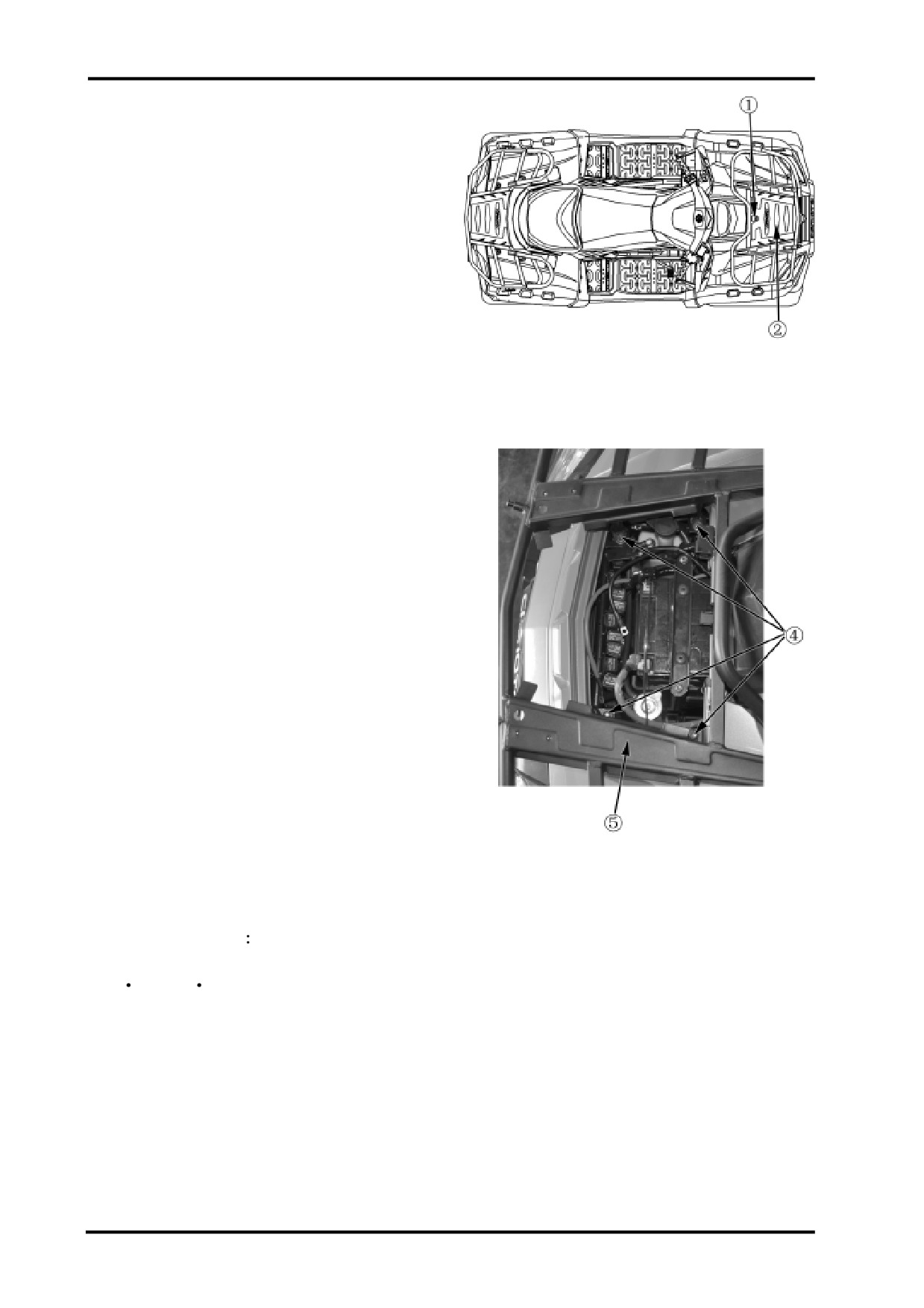
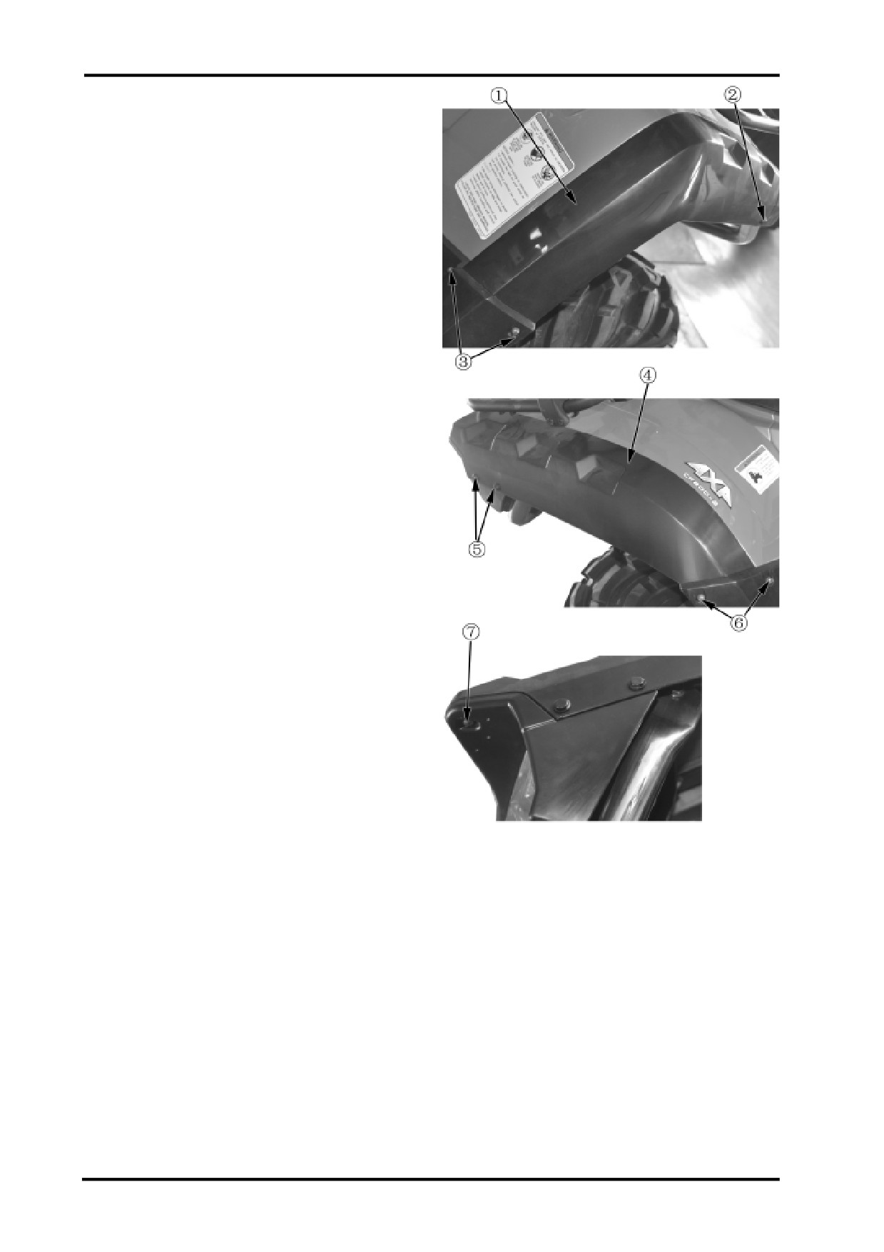
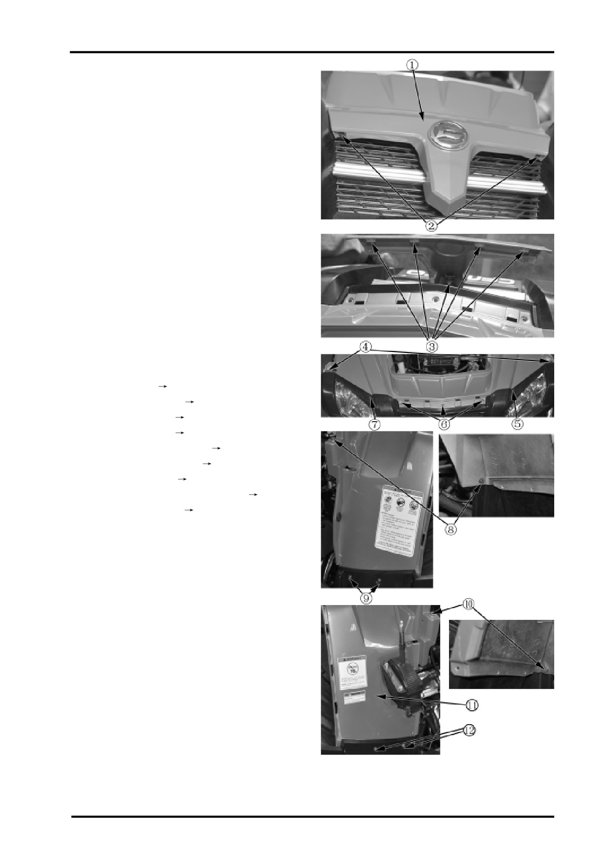
BATTERY COVER
Removal
Pull strap no.1 toward dashboard cover to disengage
the latch to remove battery cover no.2.
FRONT RACK
Removal
Remove battery cover;
Remove the 4 bolts no.4;
Remove front rack no.5.
Installation
Reverse the removal procedure for installation.
Tightening Torque
Front rack mounting bolt no.4:
35N m-45N m
2-2

2 BODY AND MUFFLER
TOOL BOX COVER
Removal
Pull strap no.2 toward passenger seat to disengage
the latch to remove tool box cover no.1.
REAR RACK
Removal
Remove the 4 bolts no.3;
Remove rear rack no.4.
Installation
Reverse the removal procedure for installation.
Tightening Torque
Rear rack mounting bolt no.3:
35N m-45N m
2-3

PASSENGER SEAT
Removal
Pull upward strap no.2 and lift passenger seat back
to remove passenger seat no.1.
Installation
Reverse the removal procedure for installation.
DRIVER SEAT
Removal
Remove passenger seat;
Disengage driver seat latch no.4;
Remove driver seat no.3.
Installation
Reverse the removal procedure for installation.
Check if the driver seat is secured and in place after
installation.
2-4

2 BODY AND MUFFLER
AIR FILTER COVER
Removal
Remove passenger seat(
2-4);
Remove driver seat(
2-4);
Lift the rear of air filter cover no.1 to disengage plastic
latches then pull the air filter cover backward to re-
move it.
Installation
Reverse the removal procedure for installation.
DASHBOARD COVER
Remove passenger seat set(
2-4);
Remove driver seat(
2-4);
Remove air filter cover(
2-5);
Remove push rivets no.4;
Remove tapping screws no.3;
Remove dashboard cover no.2;
Unplug dashboard connectors no.5;
Unplug cigarette lighter connector no.6;
Unplug ignition switch connector no.7.
Installation
Reverse the removal procedure and direction for
installation.
2-5

GEARSHIFT LEVER KNOB
Removal
Loosen locking nut no.2;
Remove gearshift lever knob by turning it
counterclockwise.
Installation
Reverse the removal procedure and direction for
installation.
GEARSHIFT LEVER INDICATOR
Removal
Remove gearshift lever knob;
Remove screw no.4;
Remove lever indicator no.3.
Installation
Reverse the removal procedure and direction for
installation.
LH SIDE PANEL
Removal
Remove passenger seat set(
2-4);
Remove driver seat(
2-4);
Remove air filter cover(
2-5
Remove gearshift lever knob ;
Remove lever indicator;
Remove push rivets no.5;
Remove bolts no.6;
Remove tapping screws no.8 retaining front and rear
fender;
Remove latch no.9;
Remove side panel.
Installation
Reverse the removal procedure and direction for
installation.
2-6

2 BODY AND MUFFLER
RH SIDE PANEL
Removal
Remove passenger seat(
2-4);
Remove driver seat(
2-4);
Remove air filter cover(
2-5);
Remove push rivets no.1;
Remove bolts no.2;
Remove tapping screws no.4;
Remove push rivets no.5;
Remove RH side panel.
Installation
Reverse the removal procedure and direction for
installation.
FRONT FENDER EXTENSION,LH
Removal
Remove bolts&nuts no.8;
Remove push rivet no.7;
Disengage plastic latches;
Remove front LH fender extension no.6.
Installation
Reverse the removal procedure and direction for
installation.
2-7
FRONT FENDER EXTENSION,RH
Removal
Remove bolts&nuts no.3;
Remove push rivet no.2;
Disengage plastic latches;
Remove front RH fender extension no.1.
Installation
Reverse the removal procedure and direction for
installation.
REAR FENDER EXTENSION,LH
Removal
Remove push rivets no.5;
Remove bolts&nuts no.6;
Remove tapping screw no.7;
Disengage plastic latches;
Remove rear fender extension,LH no.4.
Installation
Reverse the removal procedure and direction
for installation.
REAR FENDER EXTENSION,RH
Refer to rear LH Fender Extension
Removal&Installation.
2-8
2 BODY AND MUFFLER
CENTER FRONT FASCIA
Removal
Remove the 2 tapping screws no.2;
Remove push rivets no 3;
Remove center front fascia.
Installation
Reverse the removal procedure for installation.
FRONT FENDER
Removal
Remove front rack(
2-2);
Remove passenger seat(
2-4);
Remove operator seat(
2-4);
Remove air filter cover(
2-5);
Remove dashboard front cover(
2-5);
Remove gearshift lever knob(
2-6);
Remove lever indicator(
2-6);
Remove front LH&RH fender extension(
2-7);
Remove L&R side panel(
2-7);
Remove front center fascia;
Remove push rivets no.5&7;
Remove bolts no.4;
Remove tapping screws no.6;
Remove bolts no.8;
Remove bolts no.9;
Remove bolts no.10;
Remove bolts no.12;
Remove fuse box;
Remove front fender no.11.
Installation
Reverse the removal procedure for installation.
2-9

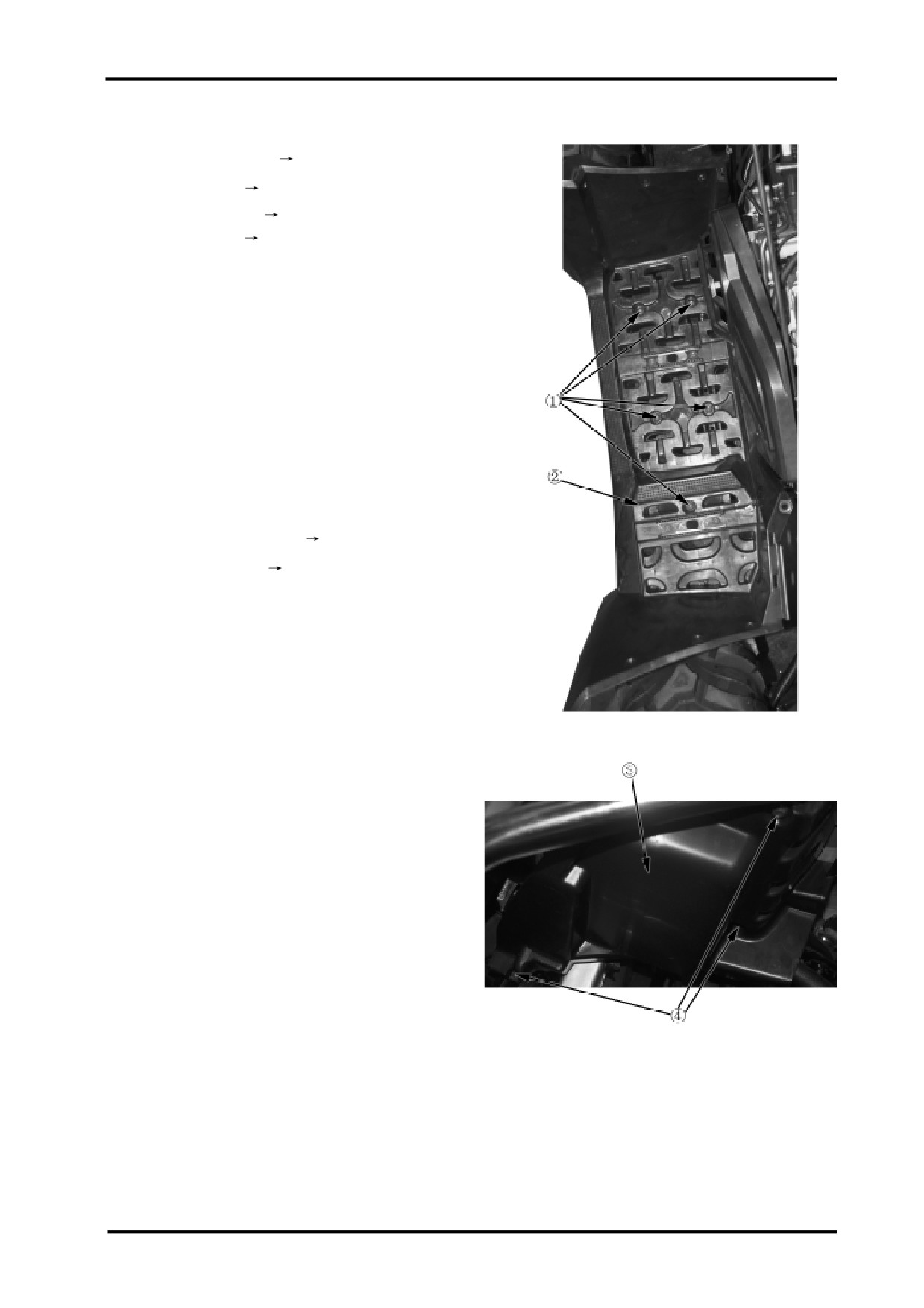
Rear Fender
Removal
Remove rear rack(
2-3);
Remove passenger seat(
2-4);
Remove driver seat(
2-4);
Remove air filter cover(
2-5
Remove rear LH&RH side panel(
2-8);
Remove LH&RH side panel(
2-6);
Remove tapping screws no.1;
Remove push rivets no.2;
Remove bolt no.4;
Remove tapping screws no.5;
Remove bolt no.6;
Remove bolt no.7;
Remove bolts no.8;
Remove rear fender no.3.
Installation
Reverse the removal procedure for installation.
2-10
2 BODY AND MUFFLER
LH FOOTBOARD
Removal
Remove passenger seat(
2-4);
Remove driver seat(
2-4);
Remove air filter cover(
2-5);
Remove side panel(
2-6);
Remove the bolts,nuts retaining front and rear
mudguard;
Remove bolts no.1;
Remove screws no.1;
Remove LH footboard no.2.
Installation
Reverse the removal procedure for installation.
RH FOOTBOARD
Removal
Remove gearshift lever knob(
2-6);
Remove lever indicator(
2-6);
Refer to LH Footboard Removal&Installation.
HEADLIGHT PROTECTOR,LH
Removal
Remove bolts no.4;
Remove headlight protector,LH.
Installation
Reverse the removal procedure for installation.
HEADLIGHT PROTECTOR,RH
Removal&Installation
Refer to LH Headlight Protector
Removal&Installation.
2-11

REAR BUMPER GUARD,LH
Removal
Remove bolt no.2;
Removal rear LH bumper guard no.2.
Installation
Reverse the removal procedure for installation.
REAR BUMPER GUARD,RH
Removal&Installation
Refer to Rear LH Bumper
Guard Removal&Installation.
REAR BUMPER
Removal
Remove rear LH&RH bumper guard.
Remove bolt no.4;
Remove rear bumper no.3.
Installation
Reverse the removal procedure for installation.
FRONT BUMPER PROTECTOR
Removal
Remove bolt no.5;
Remove front bumper protector no.6.
Installation
Reverse the removal procedure for installation.
2-12

2 BODY AND MUFFLER
FRONT BUMPER
Removal
Remove front bumper protector(
2-12);
Remove bolt no.2;
Remove front bumper no.1.1
Installation
Reverse the removal procedure for installation.
HEADLIGHT TRIM
Removal
Remove front rack(
2-2);
Remove passenger seat(
2-4);
Remove driver seat(
2-4);
Remove air filter cover(
2-5);
Remove dashboard cover(
2-5);
Remove font LH&RH fender extension(
2-7);
Remove LH&RH side panel(
2-6);
Remove center front fascia(
2-9);
Remove front fender(
2-9);
Remove bolts no.4;
Remove bolts no.5;
Disconnect headlight connectors;
Remove headlight trim no.3.
Installation
Reverse the removal procedure for installation.
2-13

TAILLIGHT TRIM
Removal
Remove rear rack(
2-3);
Remove passenger seat(
2-4);
Remove operator seat(
2-4);
Remove air filter cover(
2-5);
Remove rear LH&RH fender extension(
2-8);
Remove LH&RH side panel(
2-6);
Remove rear mudguard(
2-10);
Remove rear LH&RH bumper guard(
2-12);
Remove rear bumper(
2-12);
Remove bolts no.2;
Disconnect tail light,license plate light,rear turn lights
connectors;
Remove taillight trim no.1.
Installation
Reverse the removal procedure for installation.
REAR FASCIA
Removal
Remove rear LH&RH bumper guard(
2-12);
Remove rear bumper(
2-12);
Remove bolts of taillight trim;
Remove bolts no.4;
Remove rear fascia no.3.
Installation
Reverse the removal procedure for installation.
2-14
2 BODY AND MUFFLER
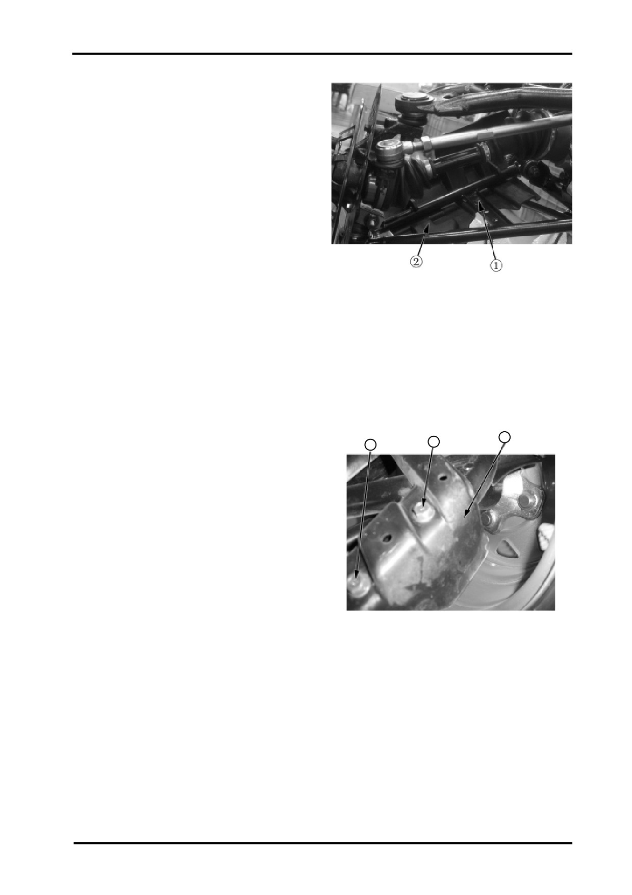
LH PROTECTOR,FRONT SUSPENSION
Removal
Remove bolt no.1;
Remove LH protector no.2.
Installation
Reverse the removal procedure for installation.
RH PROTECTOR,FRONT SUSPENSION
Refer to LH Protector,Front Suspension
Removal&Installation.
4
5
3
RH PROTECTOR,REAR SUSPENSION
Removal
Remove bolt no.3;
Remove bolt no.4;
Remove LH protector no.5.
Installation
Reverse the removal procedure for installation.
LH PROTECTOR,FRONT SUSPENSION
Refer to RH Protector,Rear Suspension
Removal&Installation.
2-15

FUEL TANK
Removal
WARNING:
Gasoline is highly flammable, therefore smoke and
fire are strictly forbidden in the work place.
Special attention should also be paid to sparks. Gaso-
line may also be explosive when it is vaporized, so
operation should be done in a well-ventilated place.
Remove passenger seat set(
2-4);
Remove driver seat(
2-4);
Remove bolts no.4;
Remove push rivets no.1;
Remove bolts no.2;
Remove bolts no.6;
Remove bolts no.7;
Remove rear plastic parts;
Disconnect fuel pump connector;
Unplug high pressure fuel line connector;
Remove fuel tank breather hose and hoses of fuel
evaporation control system;
Disconnect fuel pump connector;
Remove bolts no.5;
Remove bolts no.9;
Remove fuel tank no.8.
2-16
2 BODY AND MUFFLER
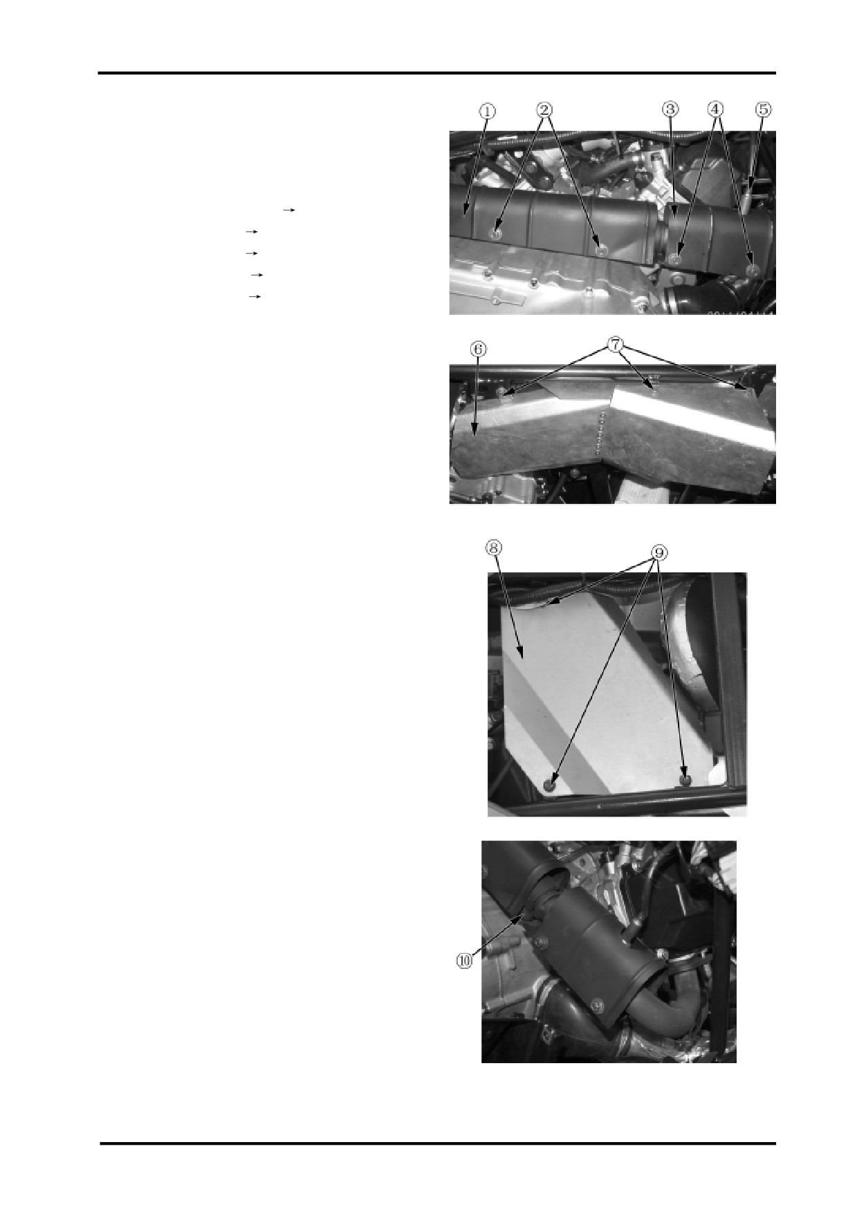
MUFFLER
WARNING:
Remove and Install muffler after it is fully cold.
Removal
Remove passenger seat set(
2-4);
Remove operator seat(
2-4);
Remove air filter cover(
2-5);
Remove RH side panel(
2-7);
Remove LH side panel(
2-6);
Remove bolts&nuts no.2;
Remove heat shield no.1;
Remove bolts&nuts no.4;
Remove heat shield no.3;
Remove bolts no.7;
Remove heat shield no.6.
Remove bolts no.9;
Remove heat shield no.8;
Remove bolt no.10 and the clamp;
Installation
Reverse the removal procedure for installation.
NOTE:
Replace the gasket on the exhaust port when installing.
2-17

Remove exhaust pipe bolts no.2;
Remove the exhaust pipe comp.no.1 of the front
cylinder;
Remove exhaust pipe bolts no.3;
Remove “Y” exhaust pipe comp. no.4;
Remove spring no.5;
Remove bolt no.6;
Remove muffler no.7.
Installation
Reverse the removal procedure for installation.
NOTE:
When installing,replace the gasket on exhaust port
and graphite collar in front exhaust pipe comp..
2-18
2 BODY AND MUFFLER
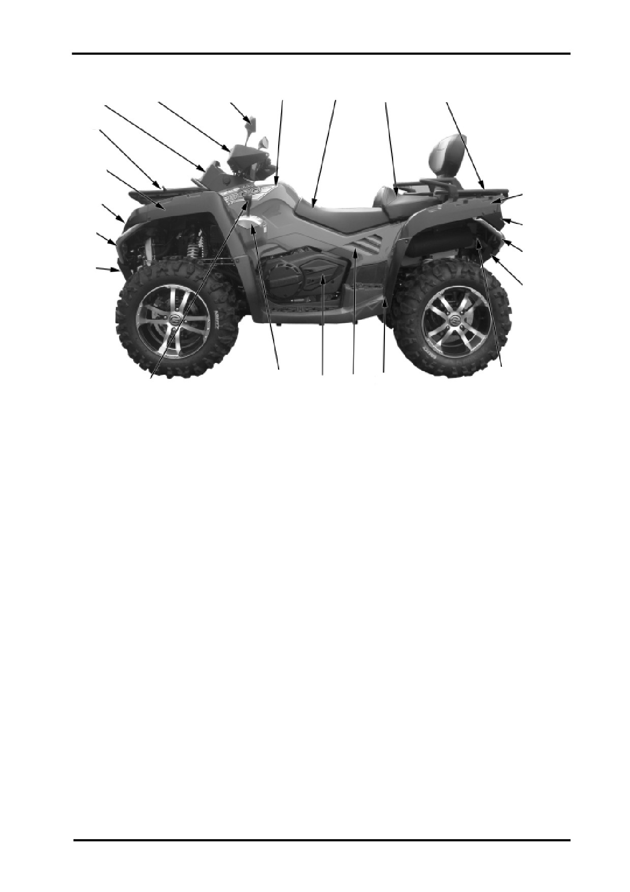
BODY AND ACCESSORIES
9
10
7
8
11
12
6
5
4
13
3
14
2
15
1
16
17
21
20
19
18
22
1.Protector,Front Bumper
2.Front Bumper
3.Headlight Trim
4.Front Fender Extension,LH
5.Front Rack
6.Dashboard Cover
7.LH Handguard
8.LH Mirror
9.Air Filter Cover
10.Driver Seat
11.Passenger Seat
12.Rear Rack
13.Rear Fender Extension,LH
14.Taillight Trim
15.Rear Bumper
16.Rear Fascia
17.Spark Arrester
18.LH Footboard
19.LH Side Panel
20.Oil Check Access Cover
21.Gearshift Lever Indicator
22.Gearshift Lever Knob
2-19
3 INSPECTION AND ADJUSTMENT
Maint enance Information………… ……3-1
Suspension Syst em……… ………… ..3-11
Maintenance Interval…………………3-2
Gearshift Linkage, Fuel System… ….3-12
Maintenance Procedure……………..3-3
Throttle Lever…………………………3-13
Steering C ol umn, Brake S ys tem…. 3-6
Cooling System…………………………3-14
3
Wheel……………………… ……………...3-9
Lighting System… ………… ……… …3-16
MAINTENANCE INFORMATION
Operation Cautions
WARNING:
z Engine exhaust contains poisonous carbon monoxide and can cause loss of consciousness result-
ing in severe injury or death.Never run an engine in an enclosed area.
z Don’t perform the maintenance immediately after the engine stops,as the exhaust system and en-
gine become very hot.Serious burns could result from the contact with the exhaust system or
engine.Wear long-sleeved uniform and gloves to operate when necessary.
z Gasoline is highly flammable, therefore smoke and fire are strictly forbidden in the work place. Spe-
cial attention should also be paid to sparks.Gasoline may also be explosive when it is vaporized, so
operation should be done in a well-ventilated place.
z Don’t get pinched by the drive system and other rotational parts.
ATTENTION:
Always position the vehicle on level ground.
3-1

3 INSPECTION AND ADJUSTMENT
Maintenance Intervals
Careful periodic maintenance will assure your vehicle good performance, reliability, economy and durability.
Inspection, adjustment, lubrication and other details are explained in below periodic maintenance chart.
ATTENTION:Maintenance intervals in the following chart are based upon average riding conditions.
Vehicles subjected to severe use must be inspected and serviced more frequently.
A:Adjust
10 hours or 300km
C:Clean
Every 25 hours or 750km
I: Inspect
Every 50 hours or 1500km
L:Lubricate
Every 100 hours or 3000km or 1year
R:Replace
Every 200 hours or 6000km or 2 years
Remark
Engine
Engine Oil and Filter
R
R
Valve Clearance
I,A
I,A
Condition of Engine Seals
I
I
Engine Mounting Fasteners
I
I
Air Filter
C
R
Coolant
I
I
I
R
Radiator Cap, Cooling System
I
I
Pressure Test
Spark Plug
I
R
Fuel System
Throttle Body
I
I,L
CVT
CVT Belt
I
R
Primary Pulley, Driven pulley
I,C
Clutch
I
3-2

3 INSPECTION AND ADJUSTMENT
O:Maintenance Interval
Maintenance Interval
Task
Inspection Item
Every 6
Criteria
Daily
Yearly
Months
Handlebar
Agility
O
Damage
O
Steering
Installing condition
O
System
Free play of ball joint pin
O
Front brake lever:0mm
Free play
O
O
Brake Lever
Main brake(FR&RR) lever: 0mm
Braking performance
O
O
Brake
Looseness&damage
O
O
lines&fittings
Brake fluid should be between
FR&RR brake fluid level
O
O
“LOWER” and “UPPER”
If front brake disc thickness is less
Brake System
Brakedisc&pads
than 2.5mm or rear brake disc
O
O
wear&damage.
thickness is less than
6.5mm,replace the disc.
Front tire:45kP(0.450kgf/cm2)
Tire pressure
O
O
Rear tire:45kPa(0.45kgf/cm2)
Crack&damage
O
O
Tread depth&abnormal
Tread depth should be more than
O
O
wear
3.0mm.
Wheel
Looseness of wheel
O
O
nuts&axle
FR wheel bearing free
O
O
play
RR wheel bearing free
O
O
play
A-arm
Free play&damage
O
O
Shock
Leaks or damages
O
O
FR Diff
Leaks&lubrication
O
O
RR Gearcase
Leaks&lubrication
O
O
Keep the oil level even with the
Gearcase/Diff
Leaks&oil level
O
O
bottom threads of fill plug hole.
3-3
3 INSPECTION AND ADJUSTMENT
Maintenance
Maintenance Interval
Item
Criteria
Daily
Every 6
Yearly
Task
Inspection Item
Months
Looseness of connection
O
O
Propshaft
Free play of splines
O
Spark plug clearance:0.8-
Spark plug condition
O
Ignition
0.9mm
Timing
O
Battery
Connections of terminals
O
Electric
Looseness&damages of
O
Routing
connections
Fuel leakage
O
Fuel
Throttle lever free play:
System
Throttle condition
O
3-5mm
Coolant level
O
O
Cooling
Leaks
O
3-4

3 INSPECTION AND ADJUSTMENT
Maintenance Item
Maintenance Interval
Criteria
Every 6
Task
Inspection Item
Daily
Yearly
Months
Lights&Turn Signal Indicators
Function
O
O
Alarming&locking Components
Function
O
Meters
Function
O
Looseness&damages
O
Exhaust Pipe&Muffler
Muffler function
O
Frame
Looseness&damages
O
Lubrication
O
Others
Abnormal conditions
O
3-5
///////////////////////////////////////