CFMoto motorcycle CF650NK. Service Manual - part 33


  Index      Manuals     CFMoto motorcycle CF650NK. Service Manual


Search            copyright infringement  


Content      ..     31      32      33      34     ..


CFMoto motorcycle CF650NK. Service Manual - part 33


16-14 ELECTRICAL SYSTEM

Battery

Charging Condition Inspection

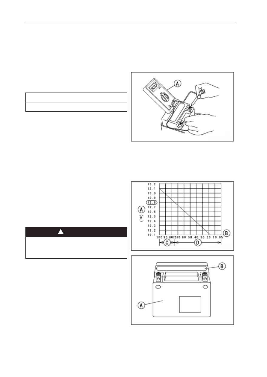
Battery charging condition can be checked by mea-
suring battery terminal voltage with a digital voltmeter
[A].


Remove:

   Seat (see Seat Removal in the Frame chapter)
   Battery Cable Cap (see Battery Removal)


Disconnect the battery terminals.

Be sure to disconnect the negative (-) cable first.

N

O

I

T

U

A

C


Measure the battery terminal voltage.

NOTE

Measure with a digital voltmeter which can be read

   one decimal place voltage.

If the reading is 12.8 V or more, no refresh charge

  is required, however, if the read is below the
   specified, refresh charge is required.

   Battery Terminal Voltage

   Standard: 12.8 V or more

   Terminal Voltage (V) [A]

   Battery Charge Rate (%) [B] Good [C]

   Refresh charge is required [D]

Refreshing Charge


Remove the battery [A] (see Battery Removal).


Do refresh charge by following method according to

    the battery terminal voltage.

This battery is sealed type.  Never remove seal-

ing cap [B] even at charging. Never add water.

Charge with current and time as stated below.

!

WARNING

NG

-------------------------------------------------------------------------------------------------------------------------------------------------------------

ELECTRICAL SYSTEM 16-15

Battery

Terminal Voltage:  11.5   less than 12.8 V

Standard Charge   1.2 Ax5~10 h (see following

chart) Quick Charge

5 A x1 h

If possible, do not quick charge. If quick charge

is done unavoidably, do standard charge later

on.

N

O

I

T

U

A

C

Terminal Voltage:  less than 11.5 V Charging

Method

1.2 Ax20 h

NOTE

Increase the charging voltage to a maximum volt-

age  of 25 V if the battery will not accept current

initially. Charge for no more than 5 minutes at the

increased voltage then check if the battery is drawing

current. If the battery will accept current decrease the

voltage and charge by the standard charging method

described on the battery case. If the battery will not

accept current after 5 min- utes, replace the battery.

Battery [A]
Battery Charger [B]
Standard Value [C]
Current starts to flow [D]

 Determine the battery condition after refresh charge.


Determine the condition of the battery left for 30

   minutes after completion of the charge by measur-
    ing the terminal voltage according to the table below.

a

i

r

e

t

i

r

C

t

n

e

m

e

g

d

u

J

r

e

h

g

i

h

r

o

V

8

.

2

1

d

o

o

G

V

8

.

2

1

n

a

h

t

r

e

w

o

l

0

.

2

1

t

n

e

i

c

if

f

u

s

n

i

e

g

r

a

h

C

¡ú

e

g

r

a

h

c

e

R

V

0

.

2

1

n

a

h

t

r

e

w

o

l

e

l

b

a

e

c

iv

r

e

s

n

U

¡ú

e

c

a

l

p

e

R

-------------------------------------------------------------------------------------------------------------------------------------------------------------

16-16 ELECTRICAL SYSTEM

Charging System

Alternator Cover Removal


Remove:

   Lower Fairing (see Lower Fairing Removal in the
   Frame chapter)
   Alternator Lead Connector [A]


Place a suitable container under the alternator cover

   [A], and remove the cover bolts [B].


Pull the alternator cover outside.

Alternator Cover Installation


Apply silicone sealant to the alternator lead grom-

   met and crankcase halves mating surface [A] on
   the front and rear sides of the cover mount.


Check that dowel pins [B] are in place on the

    crankcase.


Install a new gasket and the alternator cover.


Tighten:

   Torque - Alternator  Cover  Bolts:   9.8  N m  (1.

   0  kgf

m,  87 in

lb)

Stator Coil Removal


Remove:

    Alternator Cover (see Alternator Cover Removal)
   Holding Plate Bolt [A] and Plate  Alternator Lead
    Grommet [B] Stator Coil Bolts [C]


Remove the stator coil [D] from the alternator cover.

-------------------------------------------------------------------------------------------------------------------------------------------------------------

ELECTRICAL SYSTEM 16-17

Charging System

Stator Coil Installation


Apply a non-permanent locking agent to the threads

  of the stator coil bolts and tighten them.

  Torque - Stator Coil Bolts: 12 N m (1.2 kgf m,

  106 in

lb)


Secure the  alternator lead with  a  holding plate,

    and tighten the bolt.


Apply a non-permanent locking agent to the threads

   of the holding plate bolt.

   Torque - Alternator  Lead Holding Plate Bolt:

    9.8 N

m (1.0 kgf

m, 87 in

lb)


Apply silicone sealant to the circumference of the

   alternator lead grommet, and fit the grommet into
   the notch of the cover securely.

 Install the alternator cover (see Alternator Cover

    Installation).

Alternator Rotor Removal


Remove the alternator cover (see Alternator Cover

    Removal).


Remove the starter idle gear, torque limiter and

    shafts.


Wipe oil off the outer circumference of the rotor.


Hold the alternator rotor steady with the rotor holder

   [A], and remove the rotor bolt [B] and washer.
   Special Tool: Rotor Holder


Using the flywheel puller [A], remove the alternator

    rotor from the crankshaft.
    Special Tool -  Flywheel Puller Assembly

Alternator Rotor Installation


Using a cleaning fluid, clean off any oil or dirt on the

   following portions and dry them with a clean cloth.
   Crankshaft Tapered Portion [A]
   Alternator Rotor Tapered Portion [B]

Do not attempt to strike the alternator rotor

itself. Striking the rotor can cause the mag-

nets to lose their magnetism.

N

O

I

T

U

A

C

-------------------------------------------------------------------------------------------------------------------------------------------------------------

16-18 ELECTRICAL SYSTEM

Charging System


Install the starter gear [A] and washer [B].


Again, clean the crankshaft tapered portion [C] and

   dry there.

 Install the alternator rotor [A] while turning [B] it

   counter- clockwise.


Install the washer [A].

NOTE

Confirm the alternator rotor fit or not to the crank-

   shaft before tightening it with specified torque.

 Apply molybdenum disulfide oil solution to the

    threads and seating surface of the rotor bolt.

 Install the rotor bolt [B] and tighten it with 70 N m

   (7.0 kgf m, 52 ft lb) of torque.

 Remove the rotor bolt and washer.

 Check the tightening torque with flywheel puller.

If the rotor is not pulled out with 20 N m (2.0 kgf

m, 15 ft lb) of drawing torque, it is installed

   correctly.

If the rotor is pulled out with under 20 N m (2.0

   kgf m, 15 ft lb) of drawing torque, clean off any oil
   dirt or flaw of the crankshaft and rotor tapered portion,
   and dry them with a clean cloth. Then, confirm that
   it is not pulled out with above torque.

 Tighten the alternator rotor bolt while holding the

   alternator rotor steady with the rotor holder.

  Special Tools -  Rotor Holder

  Torque - Alternator Rotor Bolt:  155 N m (15.8

  kgf

m, 114 ft

lb)

-------------------------------------------------------------------------------------------------------------------------------------------------------------

ELECTRICAL SYSTEM 16-19

Charging System

 Install the starter double gear [B] and starter idle

   gear [C].

 Install the alternator cover (see Alternator Cover

   Installation).

Alternator Inspection

There are three types of alternator failures: short, open
(wire burned out), or loss in rotor magnetism.  A short
or open in one of the coil wires will result in either a
low output, or no output at all.  A loss in rotor
magnetism, which may be caused by dropping or hit-
ting the alternator, by leaving it near an electromag-
netic field, or just by aging, will result in low output.

 To check the alternator output voltage, do the fol

   lowing procedures.

o


Turn off the ignition switch.

o


Disconnect the alternator lead connector [A].

o


Connect the hand tester as shown in the table 1.

o


Start the engine.

o


Run it at the rpm given in the table 1.

o


Note the voltage readings (total 3 measurements).

Table 1 Alternator Output Voltage

r

e

t

s

e

T

e

g

n

a

R

s

n

o

it

c

e

n

n

o

C

g

n

i

d

a

e

R

m

p

r

0

0

0

4

t

a

o

t

)

+

(

r

e

t

s

e

T

o

t

)-

(

r

e

t

s

e

T

C

A

V

0

5

2

d

a

e

l

k

c

a

l

B

e

n

O

d

a

e

l

k

c

a

l

B

r

e

h

t

o

n

A

e

r

o

m

r

o

v

0

4

If the output voltage shows the value in the table,

   the alternator operates properly.

If the output voltage shows a much higher than the

   value in the table, the regulator/rectifier is damaged.
   A much lower reading than that given in the table
   indicates that the alternator is defective.

-------------------------------------------------------------------------------------------------------------------------------------------------------------

16-20 ELECTRICAL SYSTEM

Charging System

 Check the stator coil resistance as follows.

Stop the engine.

Connect the hand tester as shown in the table 2.

Note the readings (total 3 measurement).

r

e

t

s

e

T

e

g

n

a

R

s

n

o

it

c

e

n

n

o

C

g

n

i

d

a

e

R

o

t

)

+

(

r

e

t

s

e

T

o

t

)-

(

r

e

t

s

e

T

1

x

d

a

e

l

k

c

a

l

B

e

n

O

d

a

e

l

k

c

a

l

B

r

e

h

t

o

n

A

7

2

.

0

<

8

1

.

0

Table 2 Stator Coil Resistance

If there is more resistance than shown in the table,

   or no hand tester reading (infinity) for any two leads,
   the stator has an open lead and must be replaced.
   Much less than this resistance means the stator is
   shorted, and must be replaced.


Using the highest resistance range of the hand tester,

   measure the resistance between each of the black
   leads and chassis ground.

Any hand tester reading less than infinity ( ) indi

   cates a short, necessitating stator replacement.

If the stator coils have normal resistance, but the

   voltage check showed the alternator to be defective;
   then the rotor magnets have probably weakened,
   and the rotor must be replaced.
  

 Special Tool -  Hand Tester

-------------------------------------------------------------------------------------------------------------------------------------------------------------

ELECTRICAL SYSTEM 16-21

Regulator/Rectifier Removal


Remove Bolts [A]

Charging System

Regulator/Rectifier

 Disconnect the connector [A].

 Remove the regulator/rectifier [B].

-------------------------------------------------------------------------------------------------------------------------------------------------------------

16-22 ELECTRICAL SYSTEM

Charging System


Using a hand tester, measure the resistance be

    tween the following pair of terminals.
    If any reading is out of the speci

fi

 cation, replace 

    the regulator/recti

fi

 er with a new one.


Set the hand tester to Diode range (mv).


NOTE

 If the hand tester displays less than 1.4 V 

   when the probes are not connected, replace the 
   batteries.

   After is the engine is running(at 5000 rpm), when 
   the magneto is normal and the battery is fully 
   charged, if the voltage between the red and 
   green terminals is more than 15V or less than 
   13.5V, replace the regulator/recti

fi

 er with a new 

   one.

Red Probe (+)

Black

Probe

(-)

IN1

IN2

IN3

GND

OUT

IN1

100 - 800

IN2

100 - 800

IN3

100 - 800

GND

OUT

100 - 800

100 - 800

100 - 800

100 - 800

-------------------------------------------------------------------------------------------------------------------------------------------------------------

ELECTRICAL SYSTEM 16-23

Charging System

Starter Motor Clutch Removal/Installation

 Refer to the Alternator Rotor Removal/Installation.

Starter Motor Clutch Inspection

 Remove alternator cover (see  Alternator Cover

    Removal).


Remove starter idle gear and starter double gear.


Turn the starter motor clutch gear [A] by hand. The

    starter motor clutch gear should turn clockwise [B]
    freely, but should not turn counterclockwise [C].

If the starter motor clutch does not operate as it

   should or if it makes noise, go to the next step.

 Disassemble the starter motor clutch, and visually

   inspect the clutch parts.

If there is any worn or damaged part, replace it.

NOTE

o


Examine the starter motor clutch gear as well. Re-

    place it if it worn or damaged.

Starter Motor Clutch Disassembly


Remove:

       Alternator Rotor (see Alternator Rotor Removal)
      Starter Motor Clutch Bolts [A]

 Remove:

       Starter Motor Clutch [B]

Starter Motor Clutch Assembly

 Apply a non-permanent locking agent to the threads

   of the starter motor clutch bolts and tighten them.

   Torque - Starter Motor Clutch Bolts: 34 N m (3.

   5 kgf

m, 25 ft

lb)

-------------------------------------------------------------------------------------------------------------------------------------------------------------

16-24 ELECTRICAL SYSTEM

Charging System

Charging System Troubleshooting Chart

Charging System Malfunction

Main Fuse Inspection

Battery Condition Inspection

Charging Voltage Inspection

Allow the engine to run at 5000rpm, the 

battery voltage should be 13.5V-15V

NOTE: A fully charged battery

Stator Coil Inspection

Charging Wiring Inspection

Regulator/Rectif er Defective,Replace

Replace

1. Clean the Terminals

2. Recharge or Replace

Charging system is normal

Replace the regulator/rectif er

Replace the stator coil

Maintenance or Replace

Not Good

Not Good

Not Good

>15V

Not Good

Not Good

-------------------------------------------------------------------------------------------------------------------------------------------------------------

ELECTRICAL SYSTEM 16-25

  1.Battery

2.Starter Relay

  3.Starter Motor

4.Regulator/Rectifier

  5.Magneto Assy

6.Ignition Switch

  7.Fuse Box

Charging System Circuit

Charging System

-------------------------------------------------------------------------------------------------------------------------------------------------------------

16-26 ELECTRICAL SYSTEM

Charging System

The ignition system produces extremely high

voltage.  Do not touch the spark plugs or stick

coils while the engine is running, or you could

receive a severe electrical shock.

Do not disconnect the battery cables or any

other electrical connections when the ignition

switch is on, or while the engine is running.

This is to prevent ECU (Electric Control Unit)

damage.Do not install the battery backwards.

The negative side is grounded. This is to pre-

vent damage to the ECU.

Crankshaft Sensor Removal

 Remove:

       Lower Fairing (see Lower Fairing Removal in the
       Frame chapter)
       Right Frame Cover (see Frame Cover Removal in
        the Frame chapter) Crankshaft Sensor Lead Con
       nector [A].


Remove:

      Rubber Boot(Slide Out) [A]
       Oil Pressure Switch Lead Terminal [B]
       Clutch Cover (see Clutch Cover Removal in the
       Clutch chapter)

 Remove:

        Bolts [A]
        Crankshaft Sensor [B]


Pull out the grommet [C].

WARNING

WARNING

!

!

-------------------------------------------------------------------------------------------------------------------------------------------------------------

ELECTRICAL SYSTEM 16-27

Charging System

Crankshaft Sensor Removal


Route the crankshaft sensor lead correctly.


Tighten:

   Torque - Crankshaft Sensor Bolts:  6.0 N m (0.

   60 kgf

m, 53 in

lb)

 Apply silicone sealant [A] to the crankshaft sensor

   lead grommet.

 Install the removed parts (see appropriate chapters).

 Remove:

   Right Frame Cover (see Frame Cover Removal in
   the Frame chapter)
Crankshaft Sensor Lead Connector [A].

Crankshaft Sensor Resistance

Set the hand tester to the x 100 range

            Meter(-) Black Lead
            Meter(+) Green Lead

If there is more resistance than the specified value,

   the coil has an open lead and must be replaced.
   Much less than this resistance means the coil is
   shorted, and must be replaced.

 Using the highest resistance range of the tester,

    measure the resistance between the crankshaft sen-
   sor leads and chassis ground.
   Meter(+)  Black Lead or Green Lead


  Resistance between the Sensor and

   the Chassis Ground: 

Any tester reading less than infinity ( ) indicates a

   short, necessitating replacement of the crankshaft
   sensor assembly.

Crankshaft Sensor Inspection

-------------------------------------------------------------------------------------------------------------------------------------------------------------

16-28 ELECTRICAL SYSTEM

Ignition System

Crankshaft Sensor Peak Voltage Inspection

Be sure the battery is fully charged.

Using the peak voltage adapter [A] is a more reli

  able way to determine the condition of the crank

  shaft sensor than crankshaft sensor internal resis-

  tance measurements.

 Remove:

   Crankshaft Sensor Lead  Connector (see Crank
   shaft Sensor Removal)


Set the hand tester [B] to the x DC 10 V range,

   and connect it to peak voltage adapter.

 Connect the positive terminal of the adapter [B] to

   green lead and connect the negative terminal of the
  adaper to black lead in the crankshaft sensor
   connector.

 Turn the ignition switch and engine stop switch ON.

 Pushing the starter button, turn the engine 4~5

   seconds with the transmission gear in neutral to
   measure the crankshaft sensor peak voltage.

 Repeat the measurement 5 or more times.

   Crankshaft Sensor Peak Voltage

   Standard: 1.9 V or more

                                NOTE

If the tester reading is not specified one, check the

   crankshaft sensor.

Timing Rotor Removal

 Remove:

   Clutch Cover (see Clutch Cover Removal in the
   Clutch chapter)


Remove the timing rotor bolt [A].

 Remove the timing rotor.

Timing Rotor Installation


Fit the rotor to the crankshaft.


Tighten the rotor bolt.


Torque - Timing Rotor Bolt: 40 N

m (4.1 kgf

m, 30 ft

lb)


Install the removed parts (see appropriate chapters).

-------------------------------------------------------------------------------------------------------------------------------------------------------------

ELECTRICAL SYSTEM 16-29

Ignition System

Ignition Coil
Ignition Coil Removal


Remove the air cleaner housing (see Air Cleaner

    Housing Removal in the EFI System chapter).


Disconnect the ignition coil connectors [A].

 Pull the ignition coils [B] off the spark plugs.

Do not pry the connector part of the coil while

removing the coil.

N

O

I

T

U

A

C

Ignition Coil Installation


Insert the coil as shown being careful of the coil

   heads [A] direction.

 Connect the connectors.

N

O

I

T

U

A

C

Do not tap the coil head while installing the

coil.

Ignition Coil Inspection


Remove the ignition coils (see Ignition Coil (Ignition

   Coil together with Spark Plug Cap) Removal).


Measure the primary winding resistance [A] as

   follows.


Connect the hand tester between the coil terminals.


Set the tester to the x 10  range, and read the

   tester.

 Measure the secondary winding resistance [B] as

   follows.

 Connect the tester between the plug terminal and

    (-) coil terminal.

 Set the tester to the x1 k

range and read the

   tester.


  Ignition Coil Winding Resistance

   Primary Windings:

1.1 ~1.5 

   Secondary Windings: 10.8 ~16.2 k

If the tester does not read as specified, replace the

   coil.

-------------------------------------------------------------------------------------------------------------------------------------------------------------


Content      ..     31      32      33      34     ..