CFMoto motorcycle CF650NK. Service Manual - part 31


  Index      Manuals     CFMoto motorcycle CF650NK. Service Manual


Search            copyright infringement  


Content      ..     29      30      31      32     ..


CFMoto motorcycle CF650NK. Service Manual - part 31


14-6 STEERING

Stem, Stem Bearing Removal

 Remove:

   Front Wheel (see Front Wheel Removal in the   
   Wheels/Tires chapter)
   Headlight Assy (see Headlight Removal/  
   Installation in the Electrical System chapter)
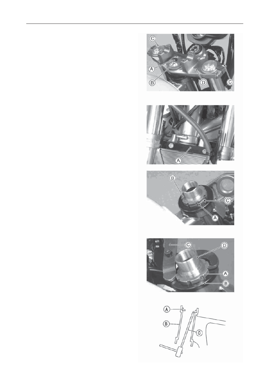
   Handlebar (see Handlebar Removal) Steering    
   Stem Head Bolt Plug [A] Steering Stem Head  
   Bolt [B] and Washer
   Front Fork Clamp Bolts (Upper) [C] (Loosen)   
   Steering Stem Head [D]

 Remove:

  Under Bracket [A] (see Upper Fairing Bracket  
   Removal in the Frame chapter)
  Front Forks (see Front Fork Removal in the 
   Suspension chapter)

 Bend the claws [A] of the claw washer straighten.

 Remove the steering stem locknut [B] and claw 

    washer [C].

 Pushing up the stem base, and remove the   

    steering stem nut [A] with stem cap [B].


 Special Tool -  Steering Stem Nut Wrench [C]

 Remove the steering stem [D] under side.

 Remove the upper stem bearing inner race and 

   bearing.

 To remove the bearing outer races [A] pressed 

   into the head pipe [B], insert a bar [C] into the 
   recesses of head pipe, and applying it to both 
   recess alternately hammer it to drive the race 
    out.

NOTE


If either steering stem bearing is damaged, it 

   is recommended that both the upper and lower 
   bearings (including outer races) should be 
    replaced with new ones.

-------------------------------------------------------------------------------------------------------------------------------------------------------------

STEERING 14-7

 Remove the lower bearing inner race [A] which   

   is pressed onto the steering stem with a suitable 
    commercially available chisel [B].

Stem, Stem Bearing Installation

 Replace the bearing outer races with new ones.

 Apply grease to the outer races, and drive them 

   into the head pipe at the same time.


Special Tool -  Bearing Driver Set [A]

 Replace the bearing inner races and oil seal with 

   new ones.

 Apply grease to the oil seal.

 Drive the lower ball bearing inner race applied 

   the grease onto the stem.

  Special Tools - Steering Stem Bearing Driver,  
  42.5 [A]


Steering Stem Bearing Driver Adapter, 41.5 [B]

 Apply grease to the lower ball bearing [A], and  

   install it onto the stem.

 Apply grease to the upper ball bearing [B] and 

   inner race [C].

 Install the stem [A] through the head pipe and 

   install the ball bearing [B] and inner race [C] on it.

 Install the stem cap [D] and steering stem nut [E].

-------------------------------------------------------------------------------------------------------------------------------------------------------------

14-8 STEERING

 Settle the inner races in place as follows.

 Tighten the steering stem nut with 39 N•m 

   (4.0 kgf•m, 29ft•lb) of torque 

fi

 rst, and loosen it 

    a fraction of a turn untilit turns lightly.  Afterward 
    tighten it again withspeci

fi

 ed torque using a stem 

    nut wrench [A] in the direction shown.

 Check that there is no play and the steering stem 

   turns smoothly without rattles. If not, the steering  
   stem bearings may be damaged.

   Special Tool -  Steering Stem Nut Wrench
   Torque - Steering Stem Nut: 20 N•m (2.0 kgf•m, 
   15 ft•lb)

 Install the claw washer [A] so that its bent side [B] 

   faces upward, and engage the bent claws with 
   the grooves of stem locknut [C].

 Hand tighten the stem locknut until it touches the 

   claw washer.

 Tighten the stem locknut clockwise until the 

  claws arealigned with the grooves (ranging from 
   2nd to 4th) of stem nut [D], and bend the 2 claws 
   downward [E].

 Install the stem head.

 Install the washer, and tighten the stem head bolt 

   withspeci

fi

 ed torque.

 Install the front forks (see Front Fork Installation 

   in the Suspension chapter).

NOTE


Tighten the upper fork clamp bolts 

fi

 rst, next the  

   stem head bolt, last the lower fork clamp bolts.


Tighten the two clamp bolts alternately two times 

   to ensure even tightening torque.


Torque - Front  Fork  Clamp  Bolts  (Upper):    

   20 N•m  (2.0 kgf•m, 15 ft•lb)

  Steering Stem Head Bolt: 108 N•m (11.0 kgf•m, 
   80 ft•lb)
  Front  Fork  Clamp  Bolts  (Lower):    20  N•m  
   (2.0  kgf•m, 15 ft•lb)

WARNING

Do not impede the handlebar turning by 
routing the cables, harnesses and hoses 
improperly.

 Install the steering stem head bolt plug.

 Install the removed parts (see appropriate   

   chapters).

Stem Bearing Lubrication

 Refer to the Steering Stem Bearing Lubrication in 

   the Periodic Maintenance chapter. 

!

-------------------------------------------------------------------------------------------------------------------------------------------------------------

STEERING 14-9

Steering Stem Warp

 Whenever the steering stem is removed, or if the 

  steering cannot be adjusted for smooth action, 
   check the steering stem for straightness.
  If the steering stem [A] is bent, replace the 
   steering stem.

Stem Cap Deterioration, Damage

 Replace the stem cap if its oil seal [A] shows 

   damage.

-------------------------------------------------------------------------------------------------------------------------------------------------------------

14-10 STEERING

Handlebar Removal

 Remove:

   Clutch Lever Assembly [A]
   Left Switch Housing [B] Left Handlebar Weight [C]

 Remove:

  Front Brake Master Cylinder [A] (see Front 
   Master Cylinder Removal in the Brakes chapter)   
   Right Switch Housing [B]
   Right Handlebar Weight [C] Throttle Grip [D]

 Remove the handlebar holder bolts [A].

 Remove the handlebar holder [B] and then pull 

    out the handlebar.

Handlebar Installation

 Align the punch mark [A] on the handlebar and 

   the corner edge [B] on the stem head.

 Tighten the front holder bolts 

fi

 rst, and then the 

   rear holder bolts. There will be a gap [A] at the 
    rear part of the handlebar holder after tightening.


  Torque - Handlebar Holder Bolts:  25 N•m (2.5 

    kgf•m, 18 ft•lb)

-------------------------------------------------------------------------------------------------------------------------------------------------------------

STEERING 14-11

 Install the clutch lever (see Clutch Lever 

    Installation in the Clutch chapter).

 Apply adhesive cement to the inside of the left 

   handlebar grip.

 Apply a non-permanent locking agent to the left 

   handlebar weight bolt.

 Install the left switch housing.

 Fit the projection [A] into a small hole [B] in the 

   handlebar.

   Torque - Left Switch Housing Screws: 3.5 N•m 
   (0.36 kgf•m, 31 in•lb)

 Install:

   Throttle Grip
   Throttle Cable Tips [A] Right Switch Housing

 Fit the projection [B] into a small hole [C] in the 

    handlebar.

   Torque - Right  Switch  Housing  Screws:     
   3.5  N•m  (0.36 kgf•m, 31 in•lb)

 Apply a non-permanent locking agent to the right 

   handlebar weight bolt.

 Install the front brake master cylinder (see Front 

  Master Cylinder Installation in the Brakes 
   chapter).

-------------------------------------------------------------------------------------------------------------------------------------------------------------

FRAME 15-1

FRAME

Table of Contents

Seats................................................................................................................................................

15-2

Front, Rear Seat Removal............................................................................................................

15-2

Front, Rear Seat Installation.........................................................................................................

15-3

Fairings.............................................................................................................................................

15-4

Lower Fairing Removal................................................................................................................

15-4

Lower Fairing Installation.............................................................................................................

15-4

Left Center Fairing Removal.........................................................................................................

15-4

Left Center Fairing Installation......................................................................................................

15-5

Right Center Fairing Removal/Installation....................................................................................

15-5

Upper Fairing Removal................................................................................................................

15-5

Upper Fairing Installation.............................................................................................................

15-5

Upper Fairing Bracket Removal...................................................................................................

15-5

Left Inner Fairing Removal........................................................................................................... 15-6
Left Inner Fairing Installation........................................................................................................ 15-6
Right Inner Fairing Removal/Installation.......................................................................................

15-6

Side Covers......................................................................................................................................

15-7

Left Side Cover Removal..............................................................................................................

15-7

Left Side Cover Installation...........................................................................................................

15-7

Grab Rails......................................................................................................................................... 15-7

Grab Rails Removal.....................................................................................................................

15-7

Grab Rails Installation..................................................................................................................

15-7

Seat Covers......................................................................................................................................

15-8

Seat Cover Removal....................................................................................................................

15-8

Seat Cover Installation.................................................................................................................

15-8

Fenders............................................................................................................................................

15-9

Front Fender Removal.................................................................................................................

15-9

Front Fender Installation..............................................................................................................

15-9

Flap and Rear Fender Rear Removal...........................................................................................

15-9

Rear Fender Front Removal......................................................................................................... 15-10
Rear Fender Front Installation...................................................................................................... 15-10

Frame............................................................................................................................................... 15-11

Frame Inspection......................................................................................................................... 15-11

Footpeg Stay.................................................................................................................................... 15-12
Sidestand.......................................................................................................................................... 15-12

Sidestand Removal...................................................................................................................... 15-12
Sidestand Installation................................................................................................................... 15-12

Rear View Mirrors............................................................................................................................. 15-13

-------------------------------------------------------------------------------------------------------------------------------------------------------------

15-2 FRAME

Seats

Front Seat Removal


Insert the ignition switch key [A] into the seat 

   lock, turning the key clockwise, pulling up on the 
  rear of the seat [B], and pulling the seat 
   backward.

Rear Seat Removal


Pull out the rear seat release pin [B] in the arrow 

   direction, pulling up on the rear of the seat [A], 
    and pulling the seat backward.

-------------------------------------------------------------------------------------------------------------------------------------------------------------

FRAME 15-3

Seats

Front Seat Installation

 Slip the seat hook [A] under the brace [B] on the 

   fuel tank bracket.

 Slip projection [D] under the brace [C].

 Slip projection [E] under the brace [F].

 Push down the rear part of the seat until the lock 

   clicks.

Rear Seat Installation

 Insert projection [B] into hole [A].

 Insert projection [C] into hole [D].

 Insert seat latch [F] into latch hole [E].

-------------------------------------------------------------------------------------------------------------------------------------------------------------

15-4 FRAME

Fairings

Lower Fairing Removal

 Remove the mounting bolts [A] and lower fairing 

   [B].

Lower Fairing Installation 

 Install the lower fairing, and tighten the mounting 

   bolts.

  Torque - Lower Fairing Mounting Bolts: 8.8 
   N·m (0.90 kgf·m, 78 in·lb)

Left Center Fairing Removal

 Remove the mounting bolts [A]. 

 Pull the left center fairing [B] evenly outward to 

   clear the stoppers.

 Disconnect the turn signal lead connector [A].

 Remove the inner fairing (see Inner Fairing 

   Removal). 

 Remove the bracket screws and turn signal 

   light.

-------------------------------------------------------------------------------------------------------------------------------------------------------------

FRAME 15-5

Fairings

Left Center Fairing Installation

 Install the turn signal light to the center fairing. 

 Install the inner fairing (see Inner Fairing 

   Installation).

 Connect the turn signal lead connector. 

 Insert the projections [F], [D], [B] respectively into 

   the holes [E], [C], [A].


Install the mounting bolts.

Right Center Fairing Removal/Installation

 Right Center Fairing Removal/Installation is 

   the reverse of the Left Center Fairing Removal/
   Installation

Upper Fairing Removal

 Remove:

   Headlight Assy (see Headlight Removal/
   Installation in the Electrical System chapter)
   Mounting Bolts [A]
   Upper Fairings

Upper Fairing Installation

 For installation, reverse the removal procedure.

Upper Fairing Bracket Removal 

 Remove:

   Headlight Assy (see Headlight Removal/
   Installation in the Electrical System chapter)
   Meter Unit (seeMeter Unit Removal in the   
   Electrical System chapter)
   Bolts [A] 

 Free the following parts from the bracket.

   Clutch Cable
   Ignition Switch Lead
   Main Harness
   Brake Hose
   Throttle Cables
   Switch Housing Leads 

 Remove the upper fairing bracket [B].

 Remove:

   Clamp [A]
   Bolts [B]
   Under Bracket [C]

-------------------------------------------------------------------------------------------------------------------------------------------------------------

15-6 FRAME

Fairings

Left Inner Fairing Removal

 Remove:

   Left Center Fairings (see Center Fairing 
   Removal)
   Left Inner Fairing 
   Mounting Screws [A]

Left Inner Fairing Installation

 Tighten the mounting screws [A].


 Torque - Front Turn Signal Light Mounting  

   Screws: 1.2 N·m (0.12 kgf·m, 11 in·lb)

 Install the left inner fairing.

 Install the left center fairing (see Left Center 

   Fairing Installation)

Right Inner Fairing Removal/Installation

 Right turn signal light removal/instalation is the 

   reverse of the left turn signal light removal/
   installation.

-------------------------------------------------------------------------------------------------------------------------------------------------------------

FRAME 15-7

Side Covers

Left Side Cover Removal 

 Remove the front seat (see Front Seat Removal). 

 Remove the bolt [A]. 

 Pull the side cover [B] evenly outward to clear 

   the stoppers.

Left Side Cover Installation 

 Insert the tabs [A] into the holes. 

 Tighten the bolt. 

 Install the front seat (see Front Seat Installation).

Grab Rails Removal

 Remove the bolts [A].

 Remove grab rails [B].

Grap Rails Installation

 Grab rails installation is the revverse of the 

    removal.

   Torque - Grab Rails Mounting Bolts: 25 N·m 
   (2.5 kgf·m, 18 ft·Ib)

-------------------------------------------------------------------------------------------------------------------------------------------------------------

15-8 FRAME

Seat Covers

Seat Cover Removal

 Remove:

   Seats (see Seat Removal)
   Grab Rails 
   Screw Rivets [B]

 Remove seat cover [F].

Seat Cover Installation

 Installation is the reverse of removal.

Rear Left Seat Cover Removal

 Remove:

   Seats (see Seat Removal)
   Grab Rails 
   Sea Cover [F]

 Remove screw [B].

 Remove rivets [E].

 Remove screw [D].

 Remove rear left seat cover.

Rear Left Seat Cover Installation

 Installation is the reverse of removal.

Rear Right Seat Cover Removal/Installation

 Refer to Rear Left Seat Cover Removal/

   Installation

.

-------------------------------------------------------------------------------------------------------------------------------------------------------------

FRAME 15-9

Fenders

Front Fender Removal 

 Remove:

   Brake Hose Clamps [C]
   Bolts [B]

 Remove the front fender [A].

Front Fender Installation

 Tighten:

   Torque - Front Fender Bolts: 3.9 N·m (0.40 
   kgf·m, 35 in·lb)

 Install the brake hose clamps to the front fender 

    holes.

Flap and Rear Fender Rear Removal

 Remove:

   Seat (see Seat Removal)
   Seat Covers (see Seat Cover Removal)
   Tail/Brake Light [B] (see Tail/Brake Light Removal 
    in the Electrical System chapter)

 Remove:

   Bolts [A]
   Tail/Brake Light nuts [A]
   Rear Turn Signal Lights

 Remove:

   Seat Lock Cable Lower End [A]

-------------------------------------------------------------------------------------------------------------------------------------------------------------

15-10 FRAME

Rear Fender Front Removal

 Remove:

   Tail/Brake Light, Turn Signal Lights (Tail/Brake 
   Light, Turn Signal Lights Removal)
   Battery (see Battery Removal in the Electrical  
   System chapter)
   Relay Box (see Relay Box Removal in the  
   Electrical System chapter)
   Starter Relay (see Starter Relay Inspection in the  
   Electrical System chapter) 
   ECU (see ECU Removal in the Electrical System 
   chapter)
   Screw [B]
   Bolt [D]
   License Plate Light Connector

Rear Fender Front Installation

 The installation is the reverse of the removal.

 Install the removed parts (see appropriate 

   chapters).

-------------------------------------------------------------------------------------------------------------------------------------------------------------


Content      ..     29      30      31      32     ..