CFMoto motorcycle CF650NK. Service Manual - part 28


  Index      Manuals     CFMoto motorcycle CF650NK. Service Manual


Search            copyright infringement  


Content      ..     26      27      28      29     ..


CFMoto motorcycle CF650NK. Service Manual - part 28


11-12 FINAL DRIVE

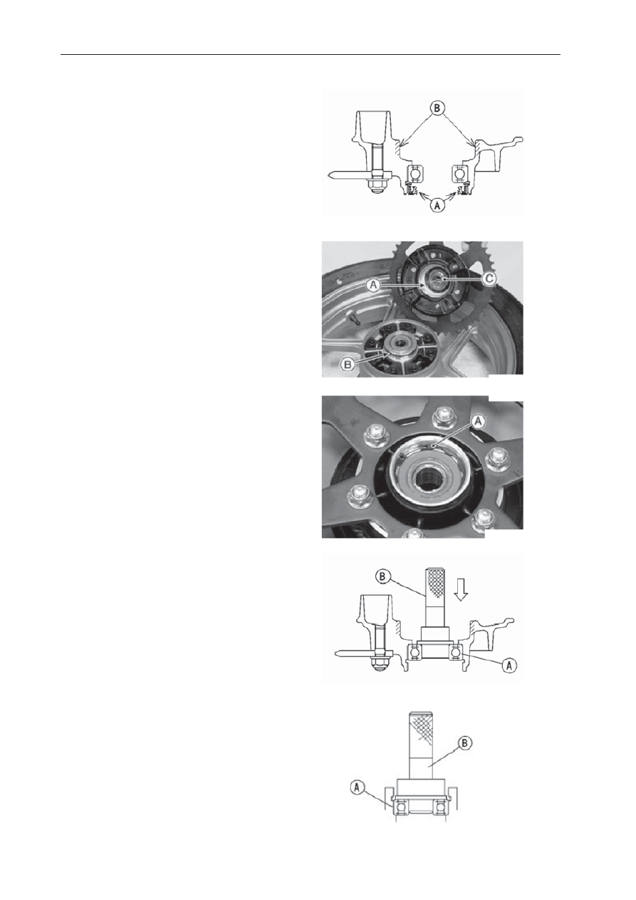
Coupling Installation

 Apply high-temperature grease to the coupling 

   grease seal lips [A].

  Apply grease to the coupling internal surface [B].

 Grease the following.

   Wheel Flange Portion [A]
   O-ring [B]

 Install the collar [C].


Coupling Bearing Removal

 Remove:

   Coupling
   Grease Seal
   Circlip [A]


Special Tool -  Inside Circlip Pliers

 Remove the bearing [A] by tapping from the 

    wheel side.
   

Special Tool -  Bearing Driver Set [B]

Coupling Bearing Installation

 Replace the bearing with a new one.

 Press in the bearing [A] until it is bottomed.


Special Tool -  Bearing Driver Set [B]

 Replace the circlip with a new one.


Special Tool -  Inside Circlip Pliers

-------------------------------------------------------------------------------------------------------------------------------------------------------------

FINAL DRIVE 11-13

 Replace the grease seal with a new one.

 Press in the grease seal so that the seal surface 

   is 

fl

 ush with the end of the hole.

 Apply high-temperature grease to the grease   

   seal lips.

   Special Tool -  Bearing Driver Set

Coupling Bearing Inspection

 Since the coupling bearing is made to extremely   

   close tolerances, the clearance can not normally 
   be measured.

NOTE

 It is not necessary to remove the coupling 

    bearing for inspection. If the bearing is removed, 
    it will need to be replaced with a new one.

 Turn the bearing in the coupling back and forth [A]   

   while checking for plays, roughness or binding.
   If the bearing play, roughness or binding is found,   
   replace the bearing.

 Examine the bearing seal [B] for tears or leakage.

  If the seal is torn or is leaking, replace the 
   bearing.

Coupling Bearing Lubrication
NOTE

Since the coupling bearing is packed with grease 

and
sealed, lubrication is not required.

Coupling Damper Inspection

 Remove the rear wheel coupling, and inspect the 

   rubber dampers [A].

 Replace the damper if it appears damaged or 

   deteriorated.

Sprocket Wear Inspection

 Visually inspect the engine and rear sprocket 

    teeth for wear and damage.
   If the teeth are worn as illustrated, replace the 
   sprocket, and inspect the drive chain wear 
   (see Drive Chain Wear Inspection in the Periodic 
   Maintenance chapter).
  Worn Tooth (Engine Sprocket) [A] Worn Tooth  
   (Rear Sprocket) [B] Direction of Rotation [C]

NOTE

 If a sprocket requires replacement, the chain is 

   probably worn also. When replacing a sprocket, 

-------------------------------------------------------------------------------------------------------------------------------------------------------------

11-14 FINAL DRIVE

Rear Sprocket Warp Inspection

 Raise the rear wheel off the ground with stand so  

   that itwill turn freely.

 Set a dial gauge [A] against the rear sprocket [B] 

   near the teeth as shown, and rotate [C] the rear 
   wheel to measure the sprocket runout (warp).   
   The difference between the highest and lowest   
   dial gauge readings is the amount of runout 
    (warp).
   If the runout exceeds the service limit, replace 
    the rear sprocket.

Rear Sprocket Warp
Standard:  

0.4 mm (0.016 in.) or less

Service Limit:  0.5 mm (0.020 in.)

-------------------------------------------------------------------------------------------------------------------------------------------------------------

BRAKES 12-1

Brakes

Table of Contents

Exploded View (Front Brake)...................... 12-2
Exploded View (Rear Brake)...................... 12-4

Specifications..............................................

12-6

Special Tools...............................................

12-7

Brake Lever, Brake Pedal............................ 12-8

Brake Lever Position Adjustment.........

12-8

Brake Pedal Position Inspection...........

12-8

Brake Pedal Position Adjustment........

12-8

Brake  Pedal  Removal....................

12-9

Brake Pedal Installation..........................

12-9

Caliper......................................................... 12-11

Front Caliper Removal........................

12-11

Rear  Caliper  Removal.......................

12-11

Rear  Caliper  Installation...................

12-11

Front Caliper Disassembly.....................

12-12

Front Caliper Assembly...........................

12-12

Rear Caliper Disassembly......................

12-12

Rear Caliper Assembly...........................

12-12

Caliper Fluid Seal Damage....................

12-12

Rear Caliper Dust Boot and
Friction Boot Damage.............................

12-12

Caliper Piston and Cylinder Damage......

12-13

Rear Caliper Holder Shaft Wear............. 12-13

Brake Pads.................................................

12-14

Front Brake Pad Removal......................

12-14

Front Brake Pad Installation..................

12-14

Rear Brake Pad Removal...........................

12-14

Rear Brake Pad Installation........................

12-14

Brake Pad Wear Inspection........................

12-14

Master Cylinder..........................................

12-15

Front Master Cylinder Removal..................

12-15

Front Master Cylinder Installation...............

12-15

Rear Master Cylinder Removal..................

12-16

Rear Master Cylinder Installation...............

12-16

Front Master Cylinder Disassembly............

12-16

Rear Master Cylinder Disassembly............

12-16

Master Cylinder Assembly..........................

12-16

Master Cylinder Inspection.........................

12-17

Brake Disc..................................................

12-18

Brake Disc Removal...................................

12-18

Brake Disc Installation................................

12-18

Brake Disc Wear........................................

12-18

Brake Disc Warp........................................

12-18

Brake Fluid.................................................

12-19

Brake Fluid Level Inspection......................

12-19

Brake Line Bleeding...................................

12-19

Brake Hose................................................

12-21

Brake Hose Removal/Installation...............

12-21

Brake Hose Inspection...............................

12-21

-------------------------------------------------------------------------------------------------------------------------------------------------------------

12-2 BRAKES

Exploded View (Front Brake)

-------------------------------------------------------------------------------------------------------------------------------------------------------------

BRAKES 12-3

Exploded View

No.

Fastener

Torque

Remarks

N·m

kgf·m

ft·lb

1

Bleed Valve

7.8

0.80

69 in·lb

2

Brake Hose Banjo Bolts

25

2.5

18

3

Brake Lever Pivot Bolt

1.0

0.10

9 in·lb

Si

4

Brake Lever Pivot Bolt Locknut

5.9

0.60

52 in·lb

5

Front Brake Disc Mounting Bolts

27

2.8

20

L

6

Front Brake Light Switch Screw

1.0

0.10

9 in·lb

7

Front Brake Reservoir Cap Screws

1.0

0.10

9 in·lb

8

Front Caliper Mounting Bolts

34

3.5

25

9

Front Master Cylinder Clamp Bolts

8.8

0.90

78 in·lb

S

B: Apply 

brake 

fl

 uid.

L:   Apply a non-permanent locking agent.
R:   Replacement Parts
S:   Follow the speci

fi

 ed tightening sequence.

Si:   Apply silicone grease (ex. PBC grease).

-------------------------------------------------------------------------------------------------------------------------------------------------------------

12-4 BRAKES

Exploded View (Rear Brake)

-------------------------------------------------------------------------------------------------------------------------------------------------------------

BRAKES 12-5

Exploded View

No.

Fastener

Torque

Remarks

N·m

kgf·m

ft·lb

1

Bleed Valve

7.8

0.80

69 in·lb

2

Brake Hose Banjo Bolts

25

2.5

18

3

Brake Pedal Bolt

8.8

0.90

78 in·lb

4

Rear Brake Disc Mounting Bolts

27

2.8

20

L

5

Rear Caliper Mounting Bolts

25

2.5

18

6

Rear Master Cylinder Mounting Bolts

25

2.5

18

7

Rear Master Cylinder Push Rod Locknut

18

1.8

13

B: Apply 

brake 

fl

 uid.

G: Apply 

grease.

L: 

Apply a non-permanent locking agent.

R:  

Replacement Parts

Si:  

Apply silicone grease (ex. PBC grease).

-------------------------------------------------------------------------------------------------------------------------------------------------------------

12-6 BRAKES

Specifi cations

Item

Standard

Service Limit

Brake Lever, Brake Pedal

Brake Lever Position
Brake Lever Free Play
Pedal Free Play
Pedal Position

5-way adjustable (to suit rider)
Non-adjustable
Non-adjustable
About 40 mm (1.6 in.) below top of footpeg

– – –

Brake Pads

Lining Thickness:
Front
Rear

4.5 mm (0.18 in.)
5.0 mm (0.20 in.)

1 mm (0.04 in.)
1 mm (0.04 in.)

Brake Disc

Thickness:
Front:
Rear
Runout

4.3 ~ 4.7 mm (0.17 ~ 0.19 in.)
4.8 ~ 5.2 mm (0.19 ~  0.20 in.)
0.15 mm (0.006 in.) or less

4.0 mm (0.16 in.)
4.5 mm (0.18 in.)
0.3 mm (0.01 in.)

Brake Fluid

Grade

DOT4 or DOT5

– – –

-------------------------------------------------------------------------------------------------------------------------------------------------------------

BRAKES 12-7

Special Tools

Inside Circlip Pliers                                                        Hand Tester

Jack                                                                               Jack Attachment

-------------------------------------------------------------------------------------------------------------------------------------------------------------

12-8 BRAKES

Brake Lever Position Adjustment

The brake lever adjuster has 5 positions so that 
the brake lever position can be adjusted to suit the 
operator’s hand.

 Push the lever forward and turn the adjuster [A] 

   to align the number with the arrow mark [B] on 
   the lever holder.

 The distance from the grip to the lever is 

   minimum at number 5 and maximum at number 1.

Brake Pedal Position Inspection

 Check that the brake pedal [A] is in the correct 

   position.
   Footpeg [B]
   Pedal Position
   Standard: About 40 mm (1.6 in.) [C] below top of
   footpeg
   If it is incorrect, adjust the brake pedal position.

Brake Pedal Position Adjustment

NOTE


Usually it is not necessary to adjust the pedal 

   position, but always adjust it when the push rod 
   locknut has been loosened.

 Remove:

   Frame Cover (see Frame Cover Removal in the   
   Frame chapter)
   Bolts [A]
   Right Footpeg Stay [B]

 Loosen the locknut [A] and turn the push rod 

   with the hex head [B] to achieve the correct pedal 
   position.
   If the length [C] shown is 70 ±1 mm (2.76 ±0.04 
   in.), the pedal position will be within the standard 
   range. 

 Tighten:

   Torque - Rear Master Cylinder Push Rod   
   Locknut: 18 N·m (1.8 kgf·m, 13 ft·lb)

 Install the footpeg stay, and tighten the bolts.


 Torque - Footpeg Stay Bolts: 34 N·m (3.5 

   kgf·m, 25 ft·lb)

 Check the brake light switch operation (see  

   Brake Light
   Switch Operation Inspection in the Periodic 
   Maintenance chapter).

-------------------------------------------------------------------------------------------------------------------------------------------------------------

BRAKES 12-9

Brake Pedal Removal

 Remove:

   Frame Cover (see Frame Cover Removal in the  
   Frame chapter)
   Bolts [A]
   Right Footpeg Stay [B]

 Remove:

   Cotter Pin [A]
   Joint Pin [B]
   Rear Brake Light Switch Spring [C]
   Return Spring [D] 

 Remove the mounting bolt [E] and take out the 

   brake pedal.

Brake Pedal Installation 

 Apply grease to the pivot shaft [A] and install the 

washer [B].

 Install:

   Brake Pedal [C]
   Washer [D]
   Brake Pedal Bolt [E]

   Torque - Brake Pedal Bolt: 8.8 N·m (0.90 
   kgf·m, 78 in·lb)

 Hook the lower end of the rear brake light switch 

   spring [A] on the pedal hook. 

 Hook the upper end of the return spring [B] on 

   the pedal hook.

 Replace the cotter pin with a new one. 

 Insert the cotter pin [A] and bend the pin ends [B].

-------------------------------------------------------------------------------------------------------------------------------------------------------------

12-10 BRAKES

 Install the right footpeg stay, and tighten the 

   bolts.

   Torque - Footpeg Stay Bolts: 34 N·m (3.5 
   kgf·m, 25 ft·lb)

 Depress the brake pedal [A] and then align the 

   bolts holes of the master cylinder [B].


 Torque - Rear Master Cylinder Mounting 

   Bolts: 25 N·m (2.5 kgf·m, 18 ft·lb)

 Check the brake pedal position (see Brake Pedal 

   Position Inspection).

-------------------------------------------------------------------------------------------------------------------------------------------------------------

BRAKES 12-11

Front Caliper Removal

● Loosen the banjo bolt [A] at the brake hose lower 


   end, and tighten it loosely. 
● Unscrew the caliper mounting bolts [B], and 


   detach the caliper [C] from the disc. 
● Unscrew the banjo bolt and remove the brake 


   hoses [D] from the caliper (see Brake Hose 


   Removal/Installation).

CAUTION

Immediately wash away any brake fluid that 

spills.

NOTE

○ 

If the caliper is to be disassembled after removal   


   and if compressed air is not available, 


   disassemble the caliper before the brake hose is 


   r

emoved (see Front Caliper Disassembly).

Rear Caliper Removal 

● Loosen the banjo bolt [A] at the brake hose lower 


   end, and tighten it loosely. 
● Unscrew the caliper mounting bolts [B], and 


   detach the caliper [C] from the disc. 
● Unscrew the banjo bolt and remove the brake 


   hose [D] from the caliper (see Brake Hose 


   Removal/Installation).

CAUTION

Immediately wash away any brake fluid that 

spills.

NOTE

○ 

If the caliper is to be disassembled after removal 


   and if compressed air is not available,  
   disassemble the caliper before the brake hose is 


   removed (see Rear Caliper Disassembly).

Caliper Installation 

● Install the caliper and brake hose lower end.
○ Replace the washers on each side of hose fitting 


   with new ones. 
● Tighten:


Torque - Caliper Mounting Bolts

   Front: 34 N·m (3.5 kgf·m, 25 ft·lb)

   Rear: 25 N·m (2.5 kgf·m, 18 ft·lb)

   Brake Hose Banjo Bolts: 25 N·m (2.5 kgf·m,  

   18 ft·lb)

● Check the fluid level in the brake reservoirs. 
● Bleed the brake line (see Brake Line Bleeding). 
● Check the brake for good braking power, no 


   brake drag, and no fluid leakage.

WARNING

Do not attempt to drive the motorcycle until 

a full brake lever or pedal is obtained by 

pumping the brake lever or pedal until the 

pads are against the disc. The brakes will not 

function on the first application of the lever or 

pedal if this is not done.

!

-------------------------------------------------------------------------------------------------------------------------------------------------------------

12-12 BRAKES

Front Caliper Disassembly

 Refer to the Caliper Rubber Parts Replacement 

   in the Periodic Maintenance chapter.

Front Caliper Assembly 

 Refer to the Caliper Rubber Parts Replacement 

   in the Periodic Maintenance chapter.

Rear Caliper Disassembly 

 Refer to the Caliper Rubber Parts Replacement 

   in the Periodic Maintenance chapter.

Rear Caliper Assembly 

 Refer to the Caliper Rubber Parts Replacement 

   in the Periodic Maintenance chapter.

Caliper Fluid Seal Damage

The 

fl

 uid seal (piston seal) [A] is placed around the 

piston to maintain clearance between the pad and 
the disc. If the seal is in a poor condition, it could 
lead the pad to wear excessively or the brake to 
drag, which may cause the temperature of the 
discs or the brake 

fl

 uid to increase. 

 Replace the 

fl

 uid seal if it exhibits any of the 

   conditions listed below.

 Brake 

fl

 uid leakage around the pad.

 Brakes overheat.

 Considerable difference in inner and outer pad 

   wear.

 Seal and piston are stuck together.

   If the 

fl

 uid seal is replaced, replace the dust seal 

   [B] as well. Also, replace all seals every other 
   time the pads are changed.

Rear Caliper Dust Boot and Friction Boot 
Damage 

 Check that the dust boot [A] and friction boot   

   [B] are not cracked, worn, swollen, or otherwise 
   damaged.
   If they show any damage, replace it.

-------------------------------------------------------------------------------------------------------------------------------------------------------------

BRAKES 12-13

Caliper Piston and Cylinder Damage 

 Visually inspect the pistons [A] and cylinder 

   surfaces [B].
   Replace the caliper if the cylinder and piston are 
   badly scores or rusty.

Rear Caliper Holder Shaft Wear

 The caliper body must slide smoothly on the 

   caliper holder shafts [A]. If the body does not 
   slide smoothly, one pad will wear more than the 
   other, pad wear will increase, and constant 
   drag on the disc will raise brake and brake 

fl

 uid 

   temperature.

 Check to see that the caliper holder shafts are 

   not badly worn or stepped, and that the rubber 
   friction boots are not damaged.
   If the rubber friction boot is damaged, replace 
   the rubber friction boot. To replace the friction 
   boot, remove the pads and the caliper bracket.
   If the caliper holder shaft is damage, replace the   
   caliper bracket.

-------------------------------------------------------------------------------------------------------------------------------------------------------------


Content      ..     26      27      28      29     ..