CFMoto motorcycle CF650NK. Service Manual - part 27
WHEELS/TIRES 10-12
Balance Weight
Number
Weight
1
10g (0.35oz.)
2
20g (0.71oz.)
3
30g (1.06oz.)
NOTE
○
Balance weights are available from cfmoto
dealers in 10, 20, and 30 grams (0.35, 0.71, and
1.06 oz.) sizes.
An imbalance of less than 10 grams (0.35 oz.)
will not usually affect running stability.
○
Do not use four or more balance weight (more
than 90gram, 3.17 oz.). If the wheel requires an
excess balance weight, disassemble the wheel to
fi
nd the cause.
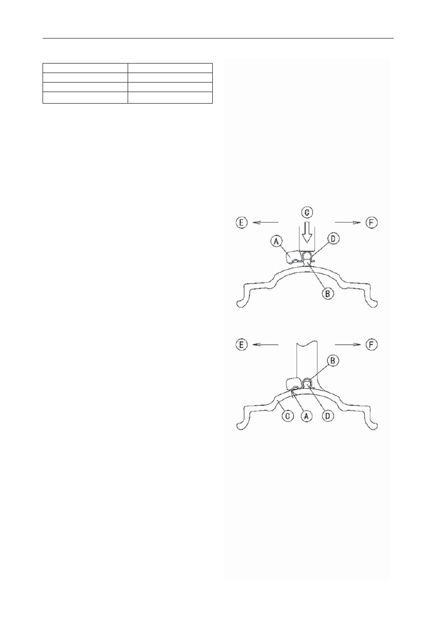
●
Slip the balance weight [A] onto the rib [B] by
pushing or lightly hammering [C] the clip [D].
Left Side [E] Right Side [F]
●
Be sure to install the balance weight.
○
Check that the blade [A] and clip [B] are fully
seated on the rim [C] and that the clip is hooked
over the rib [D].
Left Side [E]
Right Side [F]