CFMoto motorcycle CF650NK. Service Manual - part 21
ENGINE TOP END 5-31
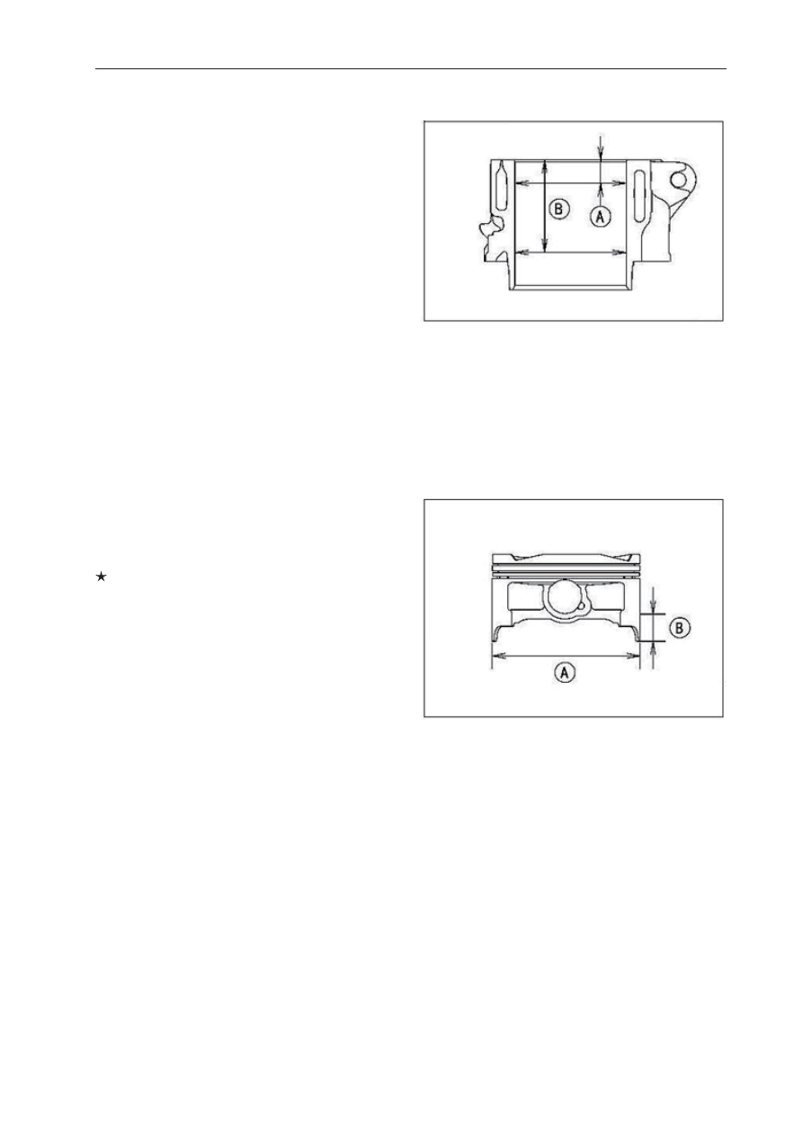
Cylinder/Pistons
Cylinder Wear
●
Since there is a difference in cylinder wear
in different directions, take a side-to-side and a
front-to-back measurement at each of the two
locations (total of four measure- ments) shown
in the
fi
gure.
10mm [A]
60mm [B]
Cylinder Inside Diameter
Standard:83.00mm~83.02mm
Service limit:83.10mm
Piston wear
●
Measure the outside diameter [A] of each piston
10mm [B] up from the bottom of the piston at a
right angle to the direction of the piston pin.
If themeasurement is under service limit, replace
the piston.
Piston diameter
Standard:82.975mm~82.995mm
Service limit : 82.90mm
Piston Ring, Piston Ring Groove Wear
●
Check for uneven groove wear by inspecting the
ring seat.