CFMoto motorcycle CF650NK. Service Manual - part 19
4-18 COOLING SYSTEM
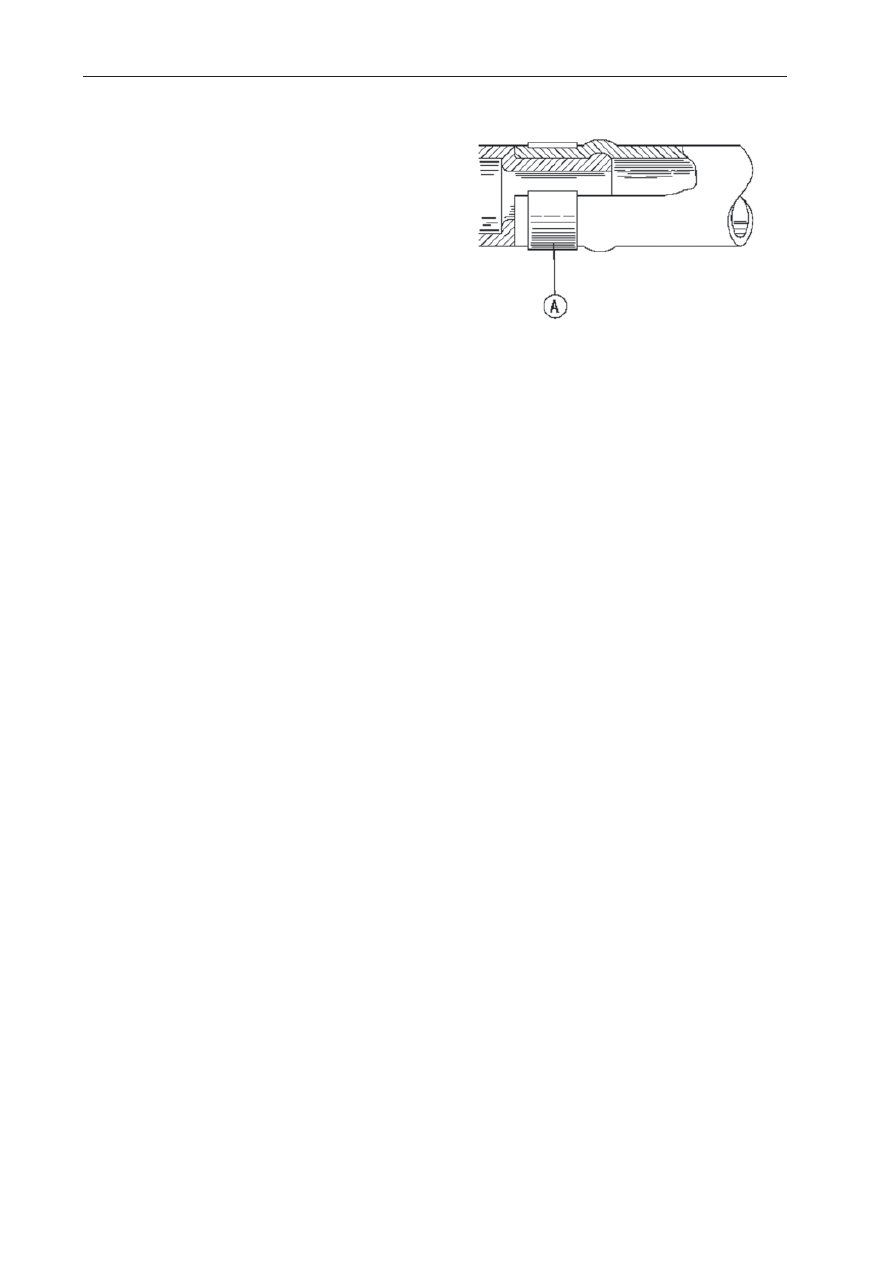
Hose and Pipes
Hose Installation
●
Install the hoses and pipes, being careful to
follow bending direction. Avoid sharp bending,
kinking,
fl
attening or twisting.
●
Run the hoses (see Cable, Wire, and Hose
Routing section in the Appendix chapter).
●
Install the clamp [A] as near as possible to the
hose end to clear the raised rib of the
fi
tting. This
will prevent the hoses from working loose.
○
The clamp screws should be positioned correctly
to prevent the clamps from contacting the other
parts.
Torque - Radiator Hose Clamp Screws: 2.0
N·m (0.20 kgf·m, 17 in·lb)
Hose Inspection
●
Refer to the Radiator Hose Damage and
Installation Condition Inspection in the Periodic
Maintenance chapter.