CFMoto motorcycle CF650NK. Service Manual - part 17


  Index      Manuals     CFMoto motorcycle CF650NK. Service Manual


Search            copyright infringement  


Content      ..     15      16      17      18     ..


CFMoto motorcycle CF650NK. Service Manual - part 17


FUEL SYSTEM (EFI) 3-65
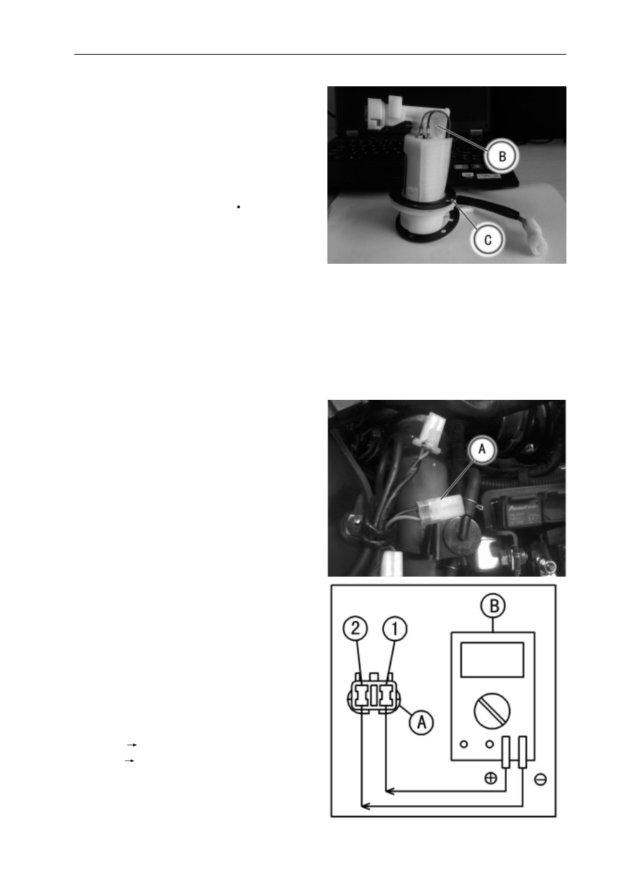
Fuel Pump

Fuel Pump Installation

 Remove dirt or dust from the fuel pump [B] by lightly

   applying compressed air.

 Replace the fuel pump gasket [C] with a new one if

   damaged.

 Tighten the fuel pump bolts to a snug fit, tighten

   them in a crisscross pattern.

   Torque - Fuel Pump Bolts: 5 N

m

 Tighten the pump bolts again in a crisscross pat-

   tern to check the tightness.

Fuel Pump Operation Inspection


   NOTE

O  

Be sure the battery is fully charged.

O  

Just listen to the pump sound in the fuel tank to

   confirm pump operation.

 Turn the ignition switch ON and make sure that the

  fuel pump operates (make light sounds) for 3
   seconds, and then stops.

 Turn the ignition switch OFF.

 If the pump does not work as described above, in-

   spect the operating voltage.

Fuel Pump Operation Inspection


NOTE

O  

Be sure the battery is fully charged.

 Turn the ignition switch OFF.

 Remove the fuel tank.

 Disconnect the fuel pump connector[A].

 Measure the operating voltage with the engine

   stopped.

 Turn the ignition switch ON.

 The tester needle should indicate battery voltage for

   3 seconds, and then 0 V.

Connections  to Pump Connectors:

       Tester(+)

terminal 1(lead B/Y)

       Tester(-)

terminal 2(lead G)

       With the ignition switch ON:

       Standard:

       Battery Voltage for 3 seconds, and then 0 V.

-------------------------------------------------------------------------------------------------------------------------------------------------------------

3-66 FUEL SYSTEM (EFI)

Fuel Pump

If  the reading stays on battery voltage, and never

   shows 0 V. Check the ECU and fuel pump relay.

If the voltage is in specification, but the pump doesn't

   work, replace the pump (see Fuel Pump Removal/
   Installation).

Pressure Regulator Removal

 The pressure regulator [A] is built into the fuel pump

   [B] and cannot be removed.

If the fuel filter is suspected of clogging or being

   damaged, replace it with the fuel pump as a set.

Pump Screen, Fuel Filter Cleaning

 The fuel filter [A] is built into the pump and cannot

   be cleaned or checked.

If the fuel filter is suspected of clogging or being

   damaged, replace it with the fuel pump as a set.

-------------------------------------------------------------------------------------------------------------------------------------------------------------

FUEL SYSTEM (EFI) 3-67

Fuel Pump Circuit

Fuel Pump

1. Engine Stop Switch
2. Fuel Pump Relay
3. Fuse Box
4. Ignition Switch
5. Starte Relay
6. Battery
7. ECU
8. Fuel Pump

-------------------------------------------------------------------------------------------------------------------------------------------------------------

3-68 FUEL SYSTEM (EFI)

Fuel Injectors

Fuel Pump Removal/Installation

 Refer to the Throttle Body Assy Disassembly/As-

   sembly.

Audible Inspection

 Start the engine.

 Apply the tip of a screwdriver [A] to the injector [B].

 Put the grip end onto your ear, and listen whether

   the injector is clicking or not.

 A sound scope [C] can also be used.

 Do the same for the other injectors.

If all the injectors click at a regular intervals, the

   injectors are good. The trouble may be related to
   the fuel line, requiring fuel pressure inspection (see
   Fuel Pressure Inspection).

 The click interval becomes shorter as the engine

   speed rises.

If any injector(s) doesn't click, the EFI circuit or the

   injector is suspect. Perform "Fuel Injector Power
   Source Voltage Inspection", first.

Fuel Injector Power Source Voltage Inspection

 Turn the ignition coil OFF.

 Remove the fuel tank.

 Remove the air filter.

 Connect a hand tester 

[B]

 to the fuel injector

   connector.

 Disonnect the fuel injector connector 

[A].

Fuel Injector Output Voltage:

Cylinder 1:

Meter (+)

B/Y lead [C]

Meter  (-)

Battery (-)

Cylinder 2:

Meter (+)

B/Y lead [C]

Meter  (-)

Battery (-)

-------------------------------------------------------------------------------------------------------------------------------------------------------------

FUEL SYSTEM (EFI) 3-69

Fuel Injector Wiring Inspection

 Connect a hand tester [A] to check the continuity

   between ECU connector [B] and fuel injector con-
   nector [C].

Cylinder 1:

ECU terminal 7

Sb/W lead [D]

Standard: continuity

ECU terminal 8

Sb/B lead [E]

Cylinder 2:

Standard: continuity

If the wiring is good, inspect the resistance of the

   injectors (see Injector Resistance Inspection).

Fuel Injectors

 Turn the ignition switch ON.

 Fuel fump input voltage is the battery voltage in first

   3 seconds, then 0 V.

If the output voltage is normal, perform "Injector Sig-

   nal Test".

If the meter does not read as specified, check the

   following:

 Main Fuse 20 A fuel pump relay fuse 15A (see Fuse

   Inspection in the Electrical System chapter)

 Fuel Pump Relay (see Relay Circuit Inspection in

   the Electrical System chapter)

 Power Source Wiring (see wiring diagram below)

-------------------------------------------------------------------------------------------------------------------------------------------------------------

3-70 FUEL SYSTEM (EFI)

Fuel Injectors

Do not use larger terminals than specified

above. A larger terminal could damage the in-

jector main harness connector (female), lead-

ing to harness repair or replacement.

Be sure to connect bulbs in series. The bulb

works as a current limiter to protect the sole-

noid in the injector from excessive current.

Test Lights Wiring

 Remove the fuel tank(see Fuel Tank removal).

 Remove the air filter housing (see Air Filter Housing

   remval).

 Disconnect the connector of fuel injector [A].

 Connect each test light set [B] to the injector sub

   harness connector [C].

 Turn the ignition switch ON.

 While cranking the engine with the starter motor,

   watch the test lights.

If the test lights flicker at regular intervals, the in-

   jector circuit in the ECU, and the wiring are good.
   Perform the "Injector Resistance Inspection".

Injector Signal Test

 Prepare two test light sets with male terminals as


shown.

   Rating of Bulb [A]: 12 V x3 ~ 3.4 W

   Terminal Width [B]: 1.8 mm (0.071 in.)

N

O

I

T

U

A

C

e

   Injector signals can be also confirmed by connect-
   ing the hand tester (x10 V AC) instead of the test
  light set to the injector main harness (female)
   connector. Crank the engine with the starter motor,
   and check to see if the hand oscillates at regular
   intervals.

If the test light doesn't flicker (or the tester needle

   doesn't oscillates), check the wiring and connec-
   tors again. If the wiring is good, check the injector
   voltage. If the wiring is good, inspect the ECU for its
   ground and power supply (see ECU Power Supply
   Inspection).

   Terminal Thickness [C]: 0.8 mm (0.031 in.)

-------------------------------------------------------------------------------------------------------------------------------------------------------------

FUEL SYSTEM (EFI) 3-71

Fuel Injectors

Fuel Injector Resistance Inspection

 Remove the fuel tank(see Fuel Tank Removal).

 Remove the air filter housing(see Air Filter Housing

   Removal).

 Disconnect the connector from the connector 

[A].


Measure the injector resistance with the hand

   tester [B].

Injector Resistance:

Standard: 12.1

20

If the reading is out of the range, perform the "Injec

   tor Unit Test".

Injector Unit Test

 Use two leads [A] and the same test light set [B] as

   in "Injector Signal Test".
   

Rating of Bulb [C]: 12 Vx (3 ~ 3.4) W

   12 V Battery [D]

N

O

I

T

U

A

C

Be sure to connect the bulb in series. The bulb

works as a current limiter to protect the sole-

noid in the injector from excessive current.

 Connect the test light set to the injector [E] as shown.

 Open and connect [F] the end of the lead to the

   battery (-) terminal repeatedly. The injector should
   click.

If the injector does not click, replace the injector.

If the injector clicks, check the wiring again. If the

   wiring is good, replace the injector (may be clogged)
   or ECU.

-------------------------------------------------------------------------------------------------------------------------------------------------------------

3-72 FUEL SYSTEM (EFI)

Fuel Injectors

Fuel Injector Circuit

1. Engine Stop Switch
2: Fuel Pump Relay
3. Fuse Box
4. Ignition Switch
5. Starter Relay
6. Battery
7. ECU
8. Fuel Injector 2
9. Fuel Injector 1

-------------------------------------------------------------------------------------------------------------------------------------------------------------

FUEL SYSTEM (EFI) 3-73

  Throttle Grip and Cables

  Throttle Grip Free Play Inspection

 Refer to the Throttle Control System Inspection in

   the Periodic Maintenance chapter.

  Throttle Grip Free Play Adjustment

 Refer to the Throttle Control System Inspection in

   the Periodic Maintenance chapter.

  Throttle Cable Installation

 Install the throttle cables in accordance with Cable,

   Wire, and Hose Routing section in the Appendix
   chapter.

 Install the lower ends of the throttle cables in the

   cable bracket on the throttle body assy after install-
   ing the upper ends of the throttle cables in the grip.

 After installation, adjust each cable properly.

Operation with incorrectly routed or improperly

adjusted cables could result in an unsafe riding

condition.

G

N

I

N

R

A

W

Throttle Cable Lubrication

 Refer to the Chassis Parts Lubrication in the Peri-

   odic Maintenance chapter.

!

-------------------------------------------------------------------------------------------------------------------------------------------------------------

3-74 FUEL SYSTEM (EFI)

Throttle Body Assy

Idle Speed Inspection

 Refer to the Idle Speed Inspection in the Periodic

   Maintenance chapter.

Engine Vacuum Synchronization Inspection/

Adjustment

 Refer to the Engine Vacuum Synchronization In-

   spection in the Periodic Maintenance chapter.

High Altitude Performance Adjustment

 Any modification is not necessary in this model since

  the inlet air pressure sensor 

[A]

 senses inlet air pres

  sure change due to high altitude and the ECU com-
  pensates the change.

Gasoline is extremely flammable and can be

explosive under certain conditions. Turn the ig-

nition switch OFF. Disconnect the battery (-)

cable terminal. Do not smoke. Make sure the

area is well-ventilated and free from any

source of flame or sparks; this includes any ap-

pliance with a pilot light.

Be prepared for fuel spillage: any spilled fuel

must be completely wiped up immediately.

 Remove:

   Fuel Tank (see Fuel Tank Removal)
   Air Filter Housing (see Air Filter Housing Removal)

 Disconnect:

   Throttle Body Sensor Connector [A]
   Fuel Hose Lower End [B]
   Evaporative emission control hose [C] of cylinder 1

 Loosen:

   Clamp [D] of cylinder 1

 Disconnect:

   Fuel injector connector [E] 

of cylinder 1

   Throttle cable 

[A] connections

 Loosen:

   Clamp [B]

 Disconnect:

   Fuel injector connector [C] of clinder 2
   Evaporative emission control hose [D] of cylinder 2

Throttle Body Assy Removal

G

N

I

N

R

A

W

!

-------------------------------------------------------------------------------------------------------------------------------------------------------------

FUEL SYSTEM (EFI) 3-75

Throttle Body Assy

 After removing the throttle body assy, stuff pieces of

  lint-free, clean cloth into the throttle body holders.

Throttle Body Assy Installation

 Istall the throttle body on the intake manifold [A].

 Install the holder clamp bolts [B] in the direction

   shown with each bolt heads [B], facing outwards.
   Install the fuel injector connector, evaporative emis-
   sion control hose, throttle cable, high pressure fuel
   line joint.

If dirt gets into the engine, excessive engine

wear and possible engine damage will occur.

G

N

I

N

R

A

W

Operation with an incorrectly routed cable

could result in an unsafe riding condition.

G

N

I

N

R

A

W

Do not remove, disassemble or adjust the

throttle position  sensor [A], throttle link mecha-

nism [B] and throttle pulley [C], because they

are adjusted or set at the manufacturer.  Ad-

justment of these parts could result in poor

performance, requiring replacement of the

throttle body assy.

N

O

I

T

U

A

C

Do not remove, disassemble or adjust the idle

adjusting screw  [A],  [B], because they are ad-

justed or set at the manufacturer. Adjustment

of these parts could result in poor performance,

requiring replacement of the throttle body assy.

N

O

I

T

U

A

C

!

!

-------------------------------------------------------------------------------------------------------------------------------------------------------------

3-76 FUEL SYSTEM (EFI)

Throttle Body Assy Disassembly

Throttle Body Assy Disassembly

 Install the fuel injector [D] and have it securely

   seated.

 Apply engine oil to the new O-rings of each injector.

 Install the fuel rail [C].

 Install the fuel rail bolts [B].

 Install the fuel injector clamp [A].

Fuel Rail Bolt Tightening Torque: 5~7N.m

Throttle Body Assy

Never drop the throttle body assy , especially

on a hard surface.  Such a shock to the body

assy can damage it.

N

O

I

T

U

A

C

 Remove the fuel injector clamps 

[A].


Remove the fuel rail bolts [B].


Remove the fuel rail [C].


Remove the fuel injector [D].

-------------------------------------------------------------------------------------------------------------------------------------------------------------

FUEL SYSTEM (EFI) 3-77

Error Code Troubleshooting

O


If any error codes are checked out, do the maintenance as per error code.

ERROR TYPE

ERROR CODE

POSSIBLE CAUSES

ERROR_TPS_LOW

1

 TPS NOT CONNECTED

 TPS CALIBRATIN ERROR

 WIRING FAULTY [Wire that connecting PIN30 ECU to PIN2 

   TPS is at potential 

 5V] or [S.C. between Wire1 that 

   connecting PIN32 ECU to PIN1 TPS and Wire2 that 
   connecting PIN30 ECU to PIN2 TPS]

 TPS FAULTY

ERROR_TPS_HIGH

2

ERROR_TEMP-
ENGINE_LOW

3

 WIRING FAULTY [S.C. between Wire1 that connecting PIN29 

   ECU to PIN1 TH2O sensor and Wire2 that connecting PIN27 
   ECU to PIN2 TH2O sensor or GND]

 TH2O SENSOR DAMAGED

ERROR_TEMP-
ENGINE_HIGH

4

 TH2O SENSOR NOT CONNECTED

 WIRING FAULTY [Short Circuit between Wire1 that connected 

    PIN29 ECU to PIN1 TH2O sensor and GND].

 TH2O SENSOR DAMAGED

ERROR_TEMP-AIR_
LOW

5

 WIRING FAULTY [S.C. between Wire1 that connecting PIN28 

   ECU to PIN1 TAIR sensor and Wire2 that connecting PIN27 
   ECU to PIN2 TAIR sensor or GND]

 TAIR SENSOR DAMAGED

ERROR_TEMP-AIR_
HIGH

6

 TAIR SENSOR NOT CONNECTED

 WIRING FAULTY

 TAIR SENSOR DAMAGED

ERROR_PRES-AIR_
LOW

7

 ECU DAMAGED

ERROR_PRES-AIR_
HIGH

8

ERROR_VB_LOW

9

 VOLTAGE REGULATOR DAMAGED

 WIRING FAULTY

ERROR_INJECTOR 
1_S.C. TO VBAT

11

 WIRING FAULTY [S.C. between Wire1 that connecting PIN7  

   ECU to PIN2 INJECTOR 1 and Wire 2 that connecting PIN87 
    MAIN RELAY to PIN1 INJECTOR 1]

  INJECTOR 1 DAMAGED

ERROR_INJECTOR 
1_S.C. TO GND

12

  WIRING FAULTY [S.C. between Wire1 that connecting PIN7 

    ECU to PIN2 INJECTOR 1 and GND]

ERROR_INJECTOR 
1_O.C.

13

  INJECTOR 1 NOT CONNECTED

  WIRING FAULTY

  INJECTOR 1 DAMAGED

ERROR_INJECTOR 
2_S.C. TO VBAT

14

  WIRING FAULTY [S.C. between Wire1 that connecting PIN8 

    ECU to PIN2 INJECTOR 2 and Wire 2 that connecting PIN87 
    MAIN RELAY to PIN1 INJECTOR 2]

  INJECTOR 2 DAMAGED

ERROR_INJECTOR 
2_S.C. TO GND

15

  WIRING FAULTY [S.C. between Wire1 that connecting PIN8 

     ECU to PIN2 INJECTOR 2 and GND]

-------------------------------------------------------------------------------------------------------------------------------------------------------------

3-78 FUEL SYSTEM (EFI)

ERROR TYPE

ERROR CODE

POSSIBLE CAUSES

ERROR_INJECTOR 2_O.C.

16

 INJECTOR 2 NOT CONNECTED

 WIRING FAULTY

 INJECTOR 2 DAMAGED

ERROR_FAN_RELAY_S.C. TO 
VBAT

23

 WIRING FAULTY [S.C. between Wire1 that 

   connecting PIN4 ECU to PIN85 FAN RELAY 
    and +BATTERY]

 FAN RELAY DAMAGED

ERROR_FAN_RELAY_O.C.

25

 FAN RELAY NOT CONNECTED

 WIRING FAULTY [S.C. between Wire that 

   connecting PIN4 ECU to PIN85 FAN RELAY and 
   GND]

 FAN RELAY DAMAGED

ERROR_MAIN_RELAY_S.C. TO 
VBAT

26

 WIRING FAULTY [S.C. between Wire1 that 

   connecting PIN3 ECU to PIN85 MAIN RELAY 
    and +BATTERY]

 MAIN RELAY DAMAGED

ERROR_MAIN_RELAY_O.C.

28

 MAIN RELAY NOT CONNECTED

 WIRING FAULTY [S.C. between Wire1 that 

  connecting PIN3 ECU to PIN85 MAIN RELAY 
   and GND]

 MAIN RELAY DAMAGED

E R R O R _ E N A B L E   S T A R T 
RELAY_S.C. TO VBAT

29

 WIRING FAULTY [S.C. between Wire1 that 

  connecting PIN5 ECU to PIN85 ENABLE 
    START RELAY and +BATTERY]

 ENABLE START RELAY DAMAGED

ERROR_DLAMP_S.C. TO VBAT

35

 WIRING FAULTY [S.C. between Wire1 that 

    c o n n e c t i n g   P I N 6   E C U   t o   D L A M P   a n d 
   +BATTERY]

 DLAMP DAMAGED

ERROR_DLAMP_O.C.

37

 DLAMP NOT CONNECTED

 WIRING FAULTY [S.C. between Wire1 that 

   connecting PIN6 ECU to DLAMP and GND]

 DLAMP DAMAGED

ERROR_LAMBDA 1

47

 LAMBDA 1 SENSOR DAMAGED

 LAMBDA 1 SENSOR NOT CONNECTED

 WIRING FAULTY [S.C. between Wire 1 that 

  connecting PIN22 ECU to PIN1 LAMBDA 1 
  and Wire 2 that connecting PIN21 ECU to PIN2 
   LAMBDA 1 or GND]

ERROR_LAMBDA 2

48

 LAMBDA 2 SENSOR DAMAGED

 LAMBDA 2 SENSOR NOT CONNECTED

 WIRING FAULTY [S.C. between Wire 1 that 

  connecting PIN23 ECU to PIN1 LAMBDA 2 
  and Wire 2 that connecting PIN21 ECU to PIN2 
   LAMBDA 2 or GND]

-------------------------------------------------------------------------------------------------------------------------------------------------------------

FUEL SYSTEM (EFI) 3-79

ERROR TYPE

ERROR CODE

POSSIBLE CAUSES

ERROR_SAFETY-SWITCH_0

49

 ROLL OVER SENSOR NOT CONNECTED

 ROLL OVER SENSOR DAMAGED

 WIRING FAULTY [Wire1 that connecting PIN31 

   ECU to PIN1 ROLL OVER SENSOR is at potential 
    

 5V]

ERROR_SAFETY-SWITCH_1

50

 R O L L OV ER S ENSO R I N  ON  CO ND IT I ON 

   (WORK)

 ROLL OVER SENSOR DAMAGED

 WIRING FAULTY [S.C. between Wire1 that 

   connecting PIN31 ECU to PIN1 ROLL OVER 
   SERNSOR and Wire2 that connecting PIN27 ECU 
    to PIN2 ROLL OVER SENSOR or GND]

ERROR_PICK-UP_O.C.

53

 PICK-UP NOT CONNECTED

 PICK-UP DAMAGED

ERROR_PICK-UP

54

 PICK-UP DAMAGED

 WIRING FAULTY [INVERTED WIRES]

 N° TOOTH PHONIC WHEEL NOT CORRECT

 GAP PICK UP NOT CORRECT

ERROR_IGNITION COIL 1

55

 IGNITION COIL 1 NOT CONNECTED

 IGNITION COIL 1 DAMAGED

 DISCHARGE BATTERY

 WIRING FAULTY

ERROR_IGNITION COIL 2

56

 IGNITION COIL 2 NOT CONNECTED

 IGNITION COIL 2 DAMAGED

 DISCHARGE BATTERY

 WIRING FAULTY

-------------------------------------------------------------------------------------------------------------------------------------------------------------

COOLING SYSTEM 4-1

Cooling System

Table of Contents

Exploded View.............................................................................................................................

4-2

Coolant Flow Chart......................................................................................................................

4-4

Speci

fi

 cations..............................................................................................................................

4-6

Special Tools................................................................................................................................

4-7

Coolant........................................................................................................................................

4-8

Coolant Deterioration Inspection.............................................................................................

4-8

Coolant Level Inspection.........................................................................................................

4-8

Coolant Draining.....................................................................................................................

4-8

Coolant Filling.........................................................................................................................

4-8

Pressure Testing.....................................................................................................................

4-8

Cooling System Flushing.........................................................................................................

4-9

Coolant Reserve Tank Removal/Installation............................................................................

4-9

Water Pump.................................................................................................................................

4-10

Water Pump Removal.............................................................................................................

4-10

Water Pump Installation..........................................................................................................

4-10

Mechanical Seal Inspection.....................................................................................................

4-11

Water Pump Housing Disassembly.........................................................................................

4-11

Water Pump Housing Assembly..............................................................................................

4-11

Impeller Assembly...................................................................................................................

4-12

Pump Impeller Inspection........................................................................................................

4-12

Radiator.......................................................................................................................................

4-13

Radiator and Radiator Fan Removal.......................................................................................

4-13

Radiator and Radiator Fan Installation....................................................................................

4-14

Radiator Inspection.................................................................................................................

4-14

Radiator Cap Inspection..........................................................................................................

4-14

Radiator Filler Neck Inspection ...............................................................................................

4-15

Thermostat..................................................................................................................................

4-16

Thermostat Removal...............................................................................................................

4-16

Thermostat Installation............................................................................................................

4-16

Thermostat Inspection.............................................................................................................

4-16

Hose and Pipes............................................................................................................................

4-18

Hose Installation......................................................................................................................

4-18

Hose Inspection......................................................................................................................

4-18

Coolant Temperature Sensor.......................................................................................................

4-19

Coolant Temperature Sensor Removal/Installation.................................................................

4-19

Coolant Temperature Sensor Inspection.................................................................................

4-19

-------------------------------------------------------------------------------------------------------------------------------------------------------------


Content      ..     15      16      17      18     ..