SINUMERIK 840D sl/828D. Job Planning. Programming Manual (2010-2018) - page 14
Tables
21.2 Operations: Availability for SINUMERIK 828D
Operation
SINUMERIK 828D
● Standard
SW24x(5)
SW26x(3)
SW28x(1)
SW24x(5)
SW26x(3)
SW28x(1)
CNC-SW
CNC-SW
CNC-SW
CNC-SW
CNC-SW
CNC-SW
○ Option
G-Tech
G-Tech
G-Tech
G-Tech
G-Tech
G-Tech
- not available
Export
Export
Adv. Export
Export
Export
Adv. Export
(gce42)
(gce62)
(gce82)
(gse42)
(gse62)
(gse82)
G643
●
●
●
●
●
●
G644
●
●
●
●
●
●
G645
●
●
●
●
●
●
G700
●
●
●
●
●
●
G710
●
●
●
●
●
●
G810 ... G819
-
-
-
-
-
-
G820 ... G829
-
-
-
-
-
-
G931
●
●
●
●
●
●
G942
●
●
●
●
●
●
G952
●
●
●
●
●
●
G961
●
●
●
●
●
●
G962
●
●
●
●
●
●
G971
●
●
●
●
●
●
G972
●
●
●
●
●
●
G973
●
●
●
●
●
●
GEOAX
●
●
●
●
●
●
GET
●
●
●
●
●
●
GETACTT
●
●
●
●
●
●
GETACTTD
●
●
●
●
●
●
GETD
-
-
●
-
-
●
GETDNO
●
●
●
●
●
●
GETEXET
●
●
●
●
●
●
GETFREELOC
●
●
●
●
●
●
GETSELT
●
●
●
●
●
●
GETT
●
●
●
●
●
●
GETTCOR
●
●
●
●
●
●
GETTENV
●
●
●
●
●
●
GETVARAP
●
●
●
●
●
●
GETVARDFT
●
●
●
●
●
●
GETVARLIM
●
●
●
●
●
●
GETVARPHU
●
●
●
●
●
●
GETVARTYP
●
●
●
●
●
●
GFRAME0 ...
< 50
< 100
< 100
< 50
< 100
< 100
GFRAME100
GOTO
●
●
●
●
●
●
GOTOB
●
●
●
●
●
●
GOTOC
●
●
●
●
●
●
GOTOF
●
●
●
●
●
●
GOTOS
●
●
●
●
●
●
Job Planning
Programming Manual, 12/2018, A5E40869460B AB
903
Tables
21.2 Operations: Availability for SINUMERIK 828D
Operation
SINUMERIK 828D
● Standard
SW24x(5)
SW26x(3)
SW28x(1)
SW24x(5)
SW26x(3)
SW28x(1)
CNC-SW
CNC-SW
CNC-SW
CNC-SW
CNC-SW
CNC-SW
○ Option
G-Tech
G-Tech
G-Tech
G-Tech
G-Tech
G-Tech
- not available
Export
Export
Adv. Export
Export
Export
Adv. Export
(gce42)
(gce62)
(gce82)
(gse42)
(gse62)
(gse82)
GP
●
●
●
●
●
●
GWPSOF
●
●
●
●
●
●
GROUP_ADDEND
●
●
●
●
●
●
GROUP_BEGIN
●
●
●
●
●
●
GROUP_END
●
●
●
●
●
●
GWPSON
●
●
●
●
●
●
H...
●
●
●
●
●
●
HOLES1
-
-
-
-
-
-
HOLES2
-
-
-
-
-
-
I
●
●
●
●
●
●
I1
●
●
●
●
●
●
IC
●
●
●
●
●
●
ICYCOF
●
●
●
●
●
●
ICYCON
●
●
●
●
●
●
ID
●
●
●
●
●
●
IDS
●
●
●
●
●
●
IF
●
●
●
●
●
●
INDEX
●
●
●
●
●
●
INIPO
●
●
●
●
●
●
INIRE
●
●
●
●
●
●
INICF
●
●
●
●
●
●
INIT
-
-
●
-
-
●
INITIAL
INT
●
●
●
●
●
●
INTERSEC
●
●
●
●
●
●
INVCCW
-
-
-
-
-
-
INVCW
-
-
-
-
-
-
INVFRAME
●
●
●
●
●
●
IP
●
●
●
●
●
●
IPOBRKA
●
●
●
●
●
●
IPOENDA
●
●
●
●
●
●
IPTRLOCK
●
●
●
●
●
●
IPTRUNLOCK
●
●
●
●
●
●
IR
●
●
●
●
●
●
ISAXIS
●
●
●
●
●
●
ISD
-
-
-
-
-
-
ISFILE
●
●
●
●
●
●
ISNUMBER
●
●
●
●
●
●
ISOCALL
-
-
-
-
-
-
Job Planning
904
Programming Manual, 12/2018, A5E40869460B AB
Tables
21.2 Operations: Availability for SINUMERIK 828D
Operation
SINUMERIK 828D
● Standard
SW24x(5)
SW26x(3)
SW28x(1)
SW24x(5)
SW26x(3)
SW28x(1)
CNC-SW
CNC-SW
CNC-SW
CNC-SW
CNC-SW
CNC-SW
○ Option
G-Tech
G-Tech
G-Tech
G-Tech
G-Tech
G-Tech
- not available
Export
Export
Adv. Export
Export
Export
Adv. Export
(gce42)
(gce62)
(gce82)
(gse42)
(gse62)
(gse82)
ISVAR
●
●
●
●
●
●
J
●
●
●
●
●
●
J1
●
●
●
●
●
●
JERKA
●
●
●
●
●
●
JERKLIM
●
●
●
●
●
●
JERKLIMA
●
●
●
●
●
●
JR
●
●
●
●
●
●
K
●
●
●
●
●
●
K1
●
●
●
●
●
●
KONT
●
●
●
●
●
●
KONTC
●
●
●
●
●
●
KONTT
●
●
●
●
●
●
KR
●
●
●
●
●
●
L
●
●
●
●
●
●
LEAD
Tool orientation
-
-
-
-
-
-
Orientation polynomial
-
-
-
-
-
-
LEADOF
-
-
-
-
-
-
LEADON
-
-
-
-
-
-
LENTOAX
●
●
●
●
●
●
LFOF
●
●
●
●
●
●
LFON
●
●
●
●
●
●
LFPOS
●
●
●
●
●
●
LFTXT
●
●
●
●
●
●
LFWP
●
●
●
●
●
●
LIFTFAST
●
●
●
●
●
●
LIMS
●
●
●
●
●
●
LLI
●
●
●
●
●
●
LN
●
●
●
●
●
●
LOCK
●
●
●
●
●
●
LONGHOLE
-
-
-
-
-
-
LOOP
●
●
●
●
●
●
Job Planning
Programming Manual, 12/2018, A5E40869460B AB
905
Tables
21.2 Operations: Availability for SINUMERIK 828D
Operations M ... R
Operation
SINUMERIK 828D
● Standard
SW24x(5)
SW26x(3)
SW28x(1)
SW24x(5)
SW26x(3)
SW28x(1)
CNC-SW
CNC-SW
CNC-SW
CNC-SW
CNC-SW
CNC-SW
○ Option
G-Tech
G-Tech
G-Tech
G-Tech
G-Tech
G-Tech
- not available
Export
Export
Adv. Export
Export
Export
Adv. Export
(gce42)
(gce62)
(gce82)
(gse42)
(gse62)
(gse82)
M0
●
●
●
●
●
●
M1
●
●
●
●
●
●
M2
●
●
●
●
●
●
M3
●
●
●
●
●
●
M4
●
●
●
●
●
●
M5
●
●
●
●
●
●
M6
●
●
●
●
●
●
M17
●
●
●
●
●
●
M19
●
●
●
●
●
●
M30
●
●
●
●
●
●
M40
●
●
●
●
●
●
M41 ... M45
●
●
●
●
●
●
M70
●
●
●
●
●
●
MASLDEF
-
-
-
-
-
-
MASLDEL
-
-
-
-
-
-
MASLOF
-
-
-
-
-
-
MASLOFS
-
-
-
-
-
-
MASLON
-
-
-
-
-
-
MATCH
●
●
●
●
●
●
MAXVAL
●
●
●
●
●
●
MCALL
●
●
●
●
●
●
MEAC
-
○
○
-
○
○
MEAFRAME
●
●
●
●
●
●
MEAS
●
●
●
●
●
●
MEASA
-
○
○
-
○
○
MEASURE
●
●
●
●
●
●
MEAW
●
●
●
●
●
●
MEAWA
-
○
○
-
○
○
MI
●
●
●
●
●
●
MINDEX
●
●
●
●
●
●
MINVAL
●
●
●
●
●
●
MIRROR
●
●
●
●
●
●
MMC
●
●
●
●
●
●
MOD
●
●
●
●
●
●
MODAXVAL
●
●
●
●
●
●
MOV
●
●
●
●
●
●
MOVT
●
●
●
●
●
●
Job Planning
906
Programming Manual, 12/2018, A5E40869460B AB
Tables
21.2 Operations: Availability for SINUMERIK 828D
Operation
SINUMERIK 828D
● Standard
SW24x(5)
SW26x(3)
SW28x(1)
SW24x(5)
SW26x(3)
SW28x(1)
CNC-SW
CNC-SW
CNC-SW
CNC-SW
CNC-SW
CNC-SW
○ Option
G-Tech
G-Tech
G-Tech
G-Tech
G-Tech
G-Tech
- not available
Export
Export
Adv. Export
Export
Export
Adv. Export
(gce42)
(gce62)
(gce82)
(gse42)
(gse62)
(gse82)
MSG
●
●
●
●
●
●
MVTOOL
●
●
●
●
●
●
N
●
●
●
●
●
●
NAMETOINT
●
●
●
●
●
●
NCK
●
●
●
●
●
●
NEWCONF
●
●
●
●
●
●
NEWMT
●
●
●
●
●
●
NEWT
-
-
-
-
-
-
NORM
●
●
●
●
●
●
NOT
●
●
●
●
●
●
NPROT
●
●
●
●
●
●
NPROTDEF
●
●
●
●
●
●
NUMBER
●
●
●
●
●
●
OEMIPO1
-
-
-
-
-
-
OEMIPO2
-
-
-
-
-
-
OF
●
●
●
●
●
●
OFFN
●
●
●
●
●
●
OMA1
-
-
-
-
-
-
OMA2
-
-
-
-
-
-
OMA3
-
-
-
-
-
-
OMA4
-
-
-
-
-
-
OMA5
-
-
-
-
-
-
OR
●
●
●
●
●
●
ORIAXES
-
-
-
-
-
-
ORIAXPOS
-
-
-
-
-
-
ORIC
-
-
-
-
-
-
ORICONCCW
-
-
-
-
-
-
ORICONCW
-
-
-
-
-
-
ORICONIO
-
-
-
-
-
-
ORICONTO
-
-
-
-
-
-
ORICURVE
-
-
-
-
-
-
ORID
-
-
-
-
-
-
ORIEULER
-
-
-
-
-
-
ORIMKS
-
-
-
-
-
-
ORIPATH
-
-
-
-
-
-
ORIPATHS
-
-
-
-
-
-
ORIPLANE
-
-
-
-
-
-
ORIRESET
-
-
-
-
-
-
ORIROTA
-
-
-
-
-
-
Job Planning
Programming Manual, 12/2018, A5E40869460B AB
907
Tables
21.2 Operations: Availability for SINUMERIK 828D
Operation
SINUMERIK 828D
● Standard
SW24x(5)
SW26x(3)
SW28x(1)
SW24x(5)
SW26x(3)
SW28x(1)
CNC-SW
CNC-SW
CNC-SW
CNC-SW
CNC-SW
CNC-SW
○ Option
G-Tech
G-Tech
G-Tech
G-Tech
G-Tech
G-Tech
- not available
Export
Export
Adv. Export
Export
Export
Adv. Export
(gce42)
(gce62)
(gce82)
(gse42)
(gse62)
(gse82)
ORIROTC
-
-
-
-
-
-
ORIROTR
-
-
-
-
-
-
ORIROTT
-
-
-
-
-
-
ORIRPY
-
-
-
-
-
-
ORIRPY2
-
-
-
-
-
-
ORIS
-
-
-
-
-
-
ORISOF
-
-
-
-
-
-
ORISOLH
-
-
-
-
-
-
ORISON
-
-
-
-
-
-
ORIVECT
-
-
-
-
-
-
ORIVIRT1
-
-
-
-
-
-
ORIVIRT2
-
-
-
-
-
-
ORIWKS
-
-
-
-
-
-
OS
○
○
○
○
○
○
OSB
○
○
○
○
○
○
OSC
-
-
-
-
-
-
OSCILL
○
○
○
○
○
○
OSCTRL
○
○
○
○
○
○
OSD
-
-
-
-
-
-
OSE
○
○
○
○
○
○
OSNSC
●
●
●
●
●
●
OSOF
-
-
-
-
-
-
OSP1
●
●
●
●
●
●
OSP2
●
●
●
●
●
●
OSS
-
-
-
-
-
-
OSSE
-
-
-
-
-
-
OST
-
-
-
-
-
-
OST1
●
●
●
●
●
●
OST2
●
●
●
●
●
●
OTOL
●
●
●
●
●
●
OVR
●
●
●
●
●
●
OVRA
●
●
●
●
●
●
OVRRAP
●
●
●
●
●
●
P
●
●
●
●
●
●
PAROT
●
●
●
●
●
●
PAROTOF
●
●
●
●
●
●
PCALL
●
●
●
●
●
●
PDELAYOF
-
-
-
-
-
-
PDELAYON
-
-
-
-
-
-
Job Planning
908
Programming Manual, 12/2018, A5E40869460B AB
Tables
21.2 Operations: Availability for SINUMERIK 828D
Operation
SINUMERIK 828D
● Standard
SW24x(5)
SW26x(3)
SW28x(1)
SW24x(5)
SW26x(3)
SW28x(1)
CNC-SW
CNC-SW
CNC-SW
CNC-SW
CNC-SW
CNC-SW
○ Option
G-Tech
G-Tech
G-Tech
G-Tech
G-Tech
G-Tech
- not available
Export
Export
Adv. Export
Export
Export
Adv. Export
(gce42)
(gce62)
(gce82)
(gse42)
(gse62)
(gse82)
PHI
-
-
-
-
-
-
PHU
●
●
●
●
●
●
PL
-
-
-
-
-
-
PM
●
●
●
●
●
●
PO
-
-
-
-
-
-
POCKET3
-
-
-
-
-
-
POCKET4
-
-
-
-
-
-
POLF
●
●
●
●
●
●
POLFA
●
●
●
●
●
●
POLFMASK
●
●
●
●
●
●
POLFMLIN
●
●
●
●
●
●
POLY
-
-
-
-
-
-
POLYPATH
-
-
-
-
-
-
PON
-
-
-
-
-
-
PONS
-
-
-
-
-
-
POS
●
●
●
●
●
●
POSA
●
●
●
●
●
●
POSM
●
●
●
●
●
●
POSMT
-
-
-
-
-
-
POSP
●
●
●
●
●
●
POSRANGE
●
●
●
●
●
●
POT
●
●
●
●
●
●
PR
●
●
●
●
●
●
PREPRO
●
●
●
●
●
●
PRESETON
●
●
●
●
●
●
PRESETONS
●
●
●
●
●
●
PRIO
●
●
●
●
●
●
PRLOC
●
●
●
●
●
●
PROC
●
●
●
●
●
●
PROTA
●
●
●
●
●
●
PROTD
●
●
●
●
●
●
PROTS
●
●
●
●
●
●
PSI
-
-
-
-
-
-
PTP
●
●
●
●
●
●
PTPG0
●
●
●
●
●
●
PTPWOC
●
●
●
●
●
●
PUNCHACC
-
-
-
-
-
-
PUTFTOC
●
●
●
●
●
●
PUTFTOCF
●
●
●
●
●
●
Job Planning
Programming Manual, 12/2018, A5E40869460B AB
909
Tables
21.2 Operations: Availability for SINUMERIK 828D
Operation
SINUMERIK 828D
● Standard
SW24x(5)
SW26x(3)
SW28x(1)
SW24x(5)
SW26x(3)
SW28x(1)
CNC-SW
CNC-SW
CNC-SW
CNC-SW
CNC-SW
CNC-SW
○ Option
G-Tech
G-Tech
G-Tech
G-Tech
G-Tech
G-Tech
- not available
Export
Export
Adv. Export
Export
Export
Adv. Export
(gce42)
(gce62)
(gce82)
(gse42)
(gse62)
(gse82)
PW
○
○
○
○
○
○
QU
●
●
●
●
●
●
R...
●
●
●
●
●
●
RAC
●
●
●
●
●
●
RDISABLE
●
●
●
●
●
●
READ
●
●
●
●
●
●
REAL
●
●
●
●
●
●
RELEASE
●
●
●
●
●
●
REP
●
●
●
●
●
●
REPEAT
●
●
●
●
●
●
REPEATB
●
●
●
●
●
●
REPOSA
●
●
●
●
●
●
REPOSH
●
●
●
●
●
●
REPOSHA
●
●
●
●
●
●
REPOSL
●
●
●
●
●
●
REPOSQ
●
●
●
●
●
●
REPOSQA
●
●
●
●
●
●
RESETMON
●
●
●
●
●
●
RET
●
●
●
●
●
●
RETB
●
●
●
●
●
●
RIC
●
●
●
●
●
●
RINDEX
●
●
●
●
●
●
RMB
●
●
●
●
●
●
RME
●
●
●
●
●
●
RMI
●
●
●
●
●
●
RMN
●
●
●
●
●
●
RND
●
●
●
●
●
●
RNDM
●
●
●
●
●
●
ROT
●
●
●
●
●
●
ROTS
●
●
●
●
●
●
ROUND
●
●
●
●
●
●
ROUNDUP
●
●
●
●
●
●
RP
●
●
●
●
●
●
RPL
●
●
●
●
●
●
RT
●
●
●
●
●
●
RTLIOF
●
●
●
●
●
●
RTLION
●
●
●
●
●
●
Job Planning
910
Programming Manual, 12/2018, A5E40869460B AB
Tables
21.2 Operations: Availability for SINUMERIK 828D
Operations S ... Z
Operation
SINUMERIK 828D
● Standard
SW24x(5)
SW26x(3)
SW28x(1)
SW24x(5)
SW26x(3)
SW28x(1)
CNC-SW
CNC-SW
CNC-SW
CNC-SW
CNC-SW
CNC-SW
○ Option
G-Tech
G-Tech
G-Tech
G-Tech
G-Tech
G-Tech
- not available
Export
Export
Adv. Export
Export
Export
Adv. Export
(gce42)
(gce62)
(gce82)
(gse42)
(gse62)
(gse82)
S
●
●
●
●
●
●
SAVE
●
●
●
●
●
●
SBLOF
●
●
●
●
●
●
SBLON
●
●
●
●
●
●
SC
●
●
●
●
●
●
SCALE
●
●
●
●
●
●
SCC
●
●
●
●
●
●
SCPARA
●
●
●
●
●
●
SD
○
○
○
○
○
○
SET
●
●
●
●
●
●
SETAL
●
●
●
●
●
●
SETDNO
●
●
●
●
●
●
SETINT
●
●
●
●
●
●
SETM
-
-
●
-
-
●
SETMS
●
●
●
●
●
●
SETMS(n)
●
●
●
●
●
●
SETMTH
●
●
●
●
●
●
SETPIECE
●
●
●
●
●
●
SETTA
●
●
●
●
●
●
SETTCOR
●
●
●
●
●
●
SETTIA
●
●
●
●
●
●
SF
●
●
●
●
●
●
SIN
●
●
●
●
●
●
SIRELAY
-
-
-
-
-
-
SIRELIN
-
-
-
-
-
-
SIRELOUT
-
-
-
-
-
-
SIRELTIME
-
-
-
-
-
-
SLOT1
-
-
-
-
-
-
SLOT2
-
-
-
-
-
-
SOFT
●
●
●
●
●
●
SOFTA
●
●
●
●
●
●
SON
-
-
-
-
-
-
SONS
-
-
-
-
-
-
SPATH
●
●
●
●
●
●
SPCOF
●
●
●
●
●
●
SPCON
●
●
●
●
●
●
SPI
●
●
●
●
●
●
Job Planning
Programming Manual, 12/2018, A5E40869460B AB
911
Tables
21.2 Operations: Availability for SINUMERIK 828D
Operation
SINUMERIK 828D
● Standard
SW24x(5)
SW26x(3)
SW28x(1)
SW24x(5)
SW26x(3)
SW28x(1)
CNC-SW
CNC-SW
CNC-SW
CNC-SW
CNC-SW
CNC-SW
○ Option
G-Tech
G-Tech
G-Tech
G-Tech
G-Tech
G-Tech
- not available
Export
Export
Adv. Export
Export
Export
Adv. Export
(gce42)
(gce62)
(gce82)
(gse42)
(gse62)
(gse82)
SPIF1
-
-
-
-
-
-
SPIF2
-
-
-
-
-
-
SPLINEPATH
○
○
○
○
○
○
SPN
-
-
-
-
-
-
SPOF
-
-
-
-
-
-
SPOS
●
●
●
●
●
●
SPOSA
●
●
●
●
●
●
SPP
-
-
-
-
-
-
SPRINT
●
●
●
●
●
●
SQRT
●
●
●
●
●
●
SR
●
●
●
●
●
●
SRA
●
●
●
●
●
●
ST
●
●
●
●
●
●
STA
●
●
●
●
●
●
START
-
-
●
-
-
●
STARTFIFO
●
●
●
●
●
●
STAT
●
●
●
●
●
●
STOLF
●
●
●
●
●
●
STOPFIFO
●
●
●
●
●
●
STOPRE
●
●
●
●
●
●
STOPREOF
●
●
●
●
●
●
STRING
●
●
●
●
●
●
STRINGFELD
●
●
●
●
●
●
STRINGIS
●
●
●
●
●
●
STRLEN
●
●
●
●
●
●
SUBSTR
●
●
●
●
●
●
SUPA
●
●
●
●
●
●
SVC
●
●
●
●
●
●
SYNFCT
●
●
●
●
●
●
SYNR
●
●
●
●
●
●
SYNRW
●
●
●
●
●
●
SYNW
●
●
●
●
●
●
T
●
●
●
●
●
●
TAN
●
●
●
●
●
●
TANG
○
○
○
○
○
○
TANGDEL
○
○
○
○
○
○
TANGOF
○
○
○
○
○
○
TANGON
○
○
○
○
○
○
Job Planning
912
Programming Manual, 12/2018, A5E40869460B AB
Tables
21.2 Operations: Availability for SINUMERIK 828D
Operation
SINUMERIK 828D
● Standard
SW24x(5)
SW26x(3)
SW28x(1)
SW24x(5)
SW26x(3)
SW28x(1)
CNC-SW
CNC-SW
CNC-SW
CNC-SW
CNC-SW
CNC-SW
○ Option
G-Tech
G-Tech
G-Tech
G-Tech
G-Tech
G-Tech
- not available
Export
Export
Adv. Export
Export
Export
Adv. Export
(gce42)
(gce62)
(gce82)
(gse42)
(gse62)
(gse82)
TCA
(828D: _TCA)
●
●
●
●
●
●
TCARR
●
●
●
●
●
●
TCI
●
●
●
●
●
●
TCOABS
●
●
●
●
●
●
TCOFR
●
●
●
●
●
●
TCOFRX
●
●
●
●
●
●
TCOFRY
●
●
●
●
●
●
TCOFRZ
●
●
●
●
●
●
THETA
-
-
-
-
-
-
TILT
-
-
-
-
-
-
TLIFT
○
○
○
○
○
○
TML
●
●
●
●
●
●
TMOF
●
●
●
●
●
●
TMON
●
●
●
●
●
●
TO
●
●
●
●
●
●
TOFF
●
●
●
●
●
●
TOFFL
●
●
●
●
●
●
TOFFOF
●
●
●
●
●
●
TOFFON
●
●
●
●
●
●
TOFFR
●
●
●
●
●
●
TOFRAME
●
●
●
●
●
●
TOFRAMEX
●
●
●
●
●
●
TOFRAMEY
●
●
●
●
●
●
TOFRAMEZ
●
●
●
●
●
●
TOLOWER
●
●
●
●
●
●
TOOLENV
●
●
●
●
●
●
TOOLGNT
●
●
●
●
●
●
TOOLGT
●
●
●
●
●
●
TOROT
●
●
●
●
●
●
TOROTOF
●
●
●
●
●
●
TOROTX
●
●
●
●
●
●
TOROTY
●
●
●
●
●
●
TOROTZ
●
●
●
●
●
●
TOUPPER
●
●
●
●
●
●
TOWBCS
●
●
●
●
●
●
TOWKCS
●
●
●
●
●
●
TOWMCS
●
●
●
●
●
●
TOWSTD
●
●
●
●
●
●
Job Planning
Programming Manual, 12/2018, A5E40869460B AB
913
Tables
21.2 Operations: Availability for SINUMERIK 828D
Operation
SINUMERIK 828D
● Standard
SW24x(5)
SW26x(3)
SW28x(1)
SW24x(5)
SW26x(3)
SW28x(1)
CNC-SW
CNC-SW
CNC-SW
CNC-SW
CNC-SW
CNC-SW
○ Option
G-Tech
G-Tech
G-Tech
G-Tech
G-Tech
G-Tech
- not available
Export
Export
Adv. Export
Export
Export
Adv. Export
(gce42)
(gce62)
(gce82)
(gse42)
(gse62)
(gse82)
TOWTCS
●
●
●
●
●
●
TOWWCS
●
●
●
●
●
●
TR
●
●
●
●
●
●
TRAANG
○
○
○
-
-
-
TRACON
○
○
○
-
-
-
TRACYL
○
○
○
○
○
○
TRAFOOF
●
●
●
●
●
●
TRAFOON
-
-
-
-
-
-
TRAILOF
●
●
●
●
●
●
TRAILON
●
●
●
●
●
●
TRANS
●
●
●
●
●
●
TRANSMIT
○
○
○
○
○
○
TRAORI
-
-
-
-
-
-
TRUE
●
●
●
●
●
●
TRUNC
●
●
●
●
●
●
TU
●
●
●
●
●
●
TURN
●
●
●
●
●
●
ULI
●
●
●
●
●
●
UNLOCK
●
●
●
●
●
●
UNTIL
●
●
●
●
●
●
UPATH
●
●
●
●
●
●
VAR
●
●
●
●
●
●
VELOLIM
●
●
●
●
●
●
VELOLIMA
●
●
●
●
●
●
WAITC
●
●
●
●
●
●
WAITE
-
-
●
-
-
●
WAITENC
●
●
●
●
●
●
WAITM
-
-
●
-
-
●
WAITMC
-
-
●
-
-
●
WAITP
●
●
●
●
●
●
WAITS
●
●
●
●
●
●
WALCS0
●
●
●
●
●
●
WALCS1
●
●
●
●
●
●
WALCS2
●
●
●
●
●
●
WALCS3
●
●
●
●
●
●
WALCS4
●
●
●
●
●
●
WALCS5
●
●
●
●
●
●
WALCS6
●
●
●
●
●
●
WALCS7
●
●
●
●
●
●
Job Planning
914
Programming Manual, 12/2018, A5E40869460B AB

Tables
21.2 Operations: Availability for SINUMERIK 828D
Operation
SINUMERIK 828D
● Standard
SW24x(5)
SW26x(3)
SW28x(1)
SW24x(5)
SW26x(3)
SW28x(1)
CNC-SW
CNC-SW
CNC-SW
CNC-SW
CNC-SW
CNC-SW
○ Option
G-Tech
G-Tech
G-Tech
G-Tech
G-Tech
G-Tech
- not available
Export
Export
Adv. Export
Export
Export
Adv. Export
(gce42)
(gce62)
(gce82)
(gse42)
(gse62)
(gse82)
WALCS8
●
●
●
●
●
●
WALCS9
●
●
●
●
●
●
WALCS10
●
●
●
●
●
●
WALIMOF
●
●
●
●
●
●
WALIMON
●
●
●
●
●
●
WHEN
●
●
●
●
●
●
WHENEVER
●
●
●
●
●
●
WHILE
●
●
●
●
●
●
WORKPIECE
●
●
●
●
●
●
WRITE
●
●
●
●
●
●
WRTPR
●
●
●
●
●
●
X
●
●
●
●
●
●
XOR
●
●
●
●
●
●
Y
●
●
●
●
●
●
Z
●
●
●
●
●
●
Job Planning
Programming Manual, 12/2018, A5E40869460B AB
915

Tables
21.3 Currently set language in the HMI
21.3
Currently set language in the HMI
The table below lists all of the languages available at the user interface.
The currently set language can be queried in the part program and in the synchronized actions
using the following system variable:
$AN_LANGUAGE_ON_HMI = <value>
<value>
Language
Language code
1
German (Germany)
GER
2
French
FRA
3
English (Great Britain)
ENG
4
Spanish
ESP
6
Italian
ITA
7
Dutch
NLD
8
Simplified Chinese
CHS
9
Swedish
SVE
18
Hungarian
HUN
19
Finnish
FIN
28
Czech
CSY
50
Portuguese (Brazil)
PTB
53
Polish
PLK
55
Danish
DAN
57
Russian
RUS
68
Slovakian
SKY
72
Rumanian
ROM
80
Traditional Chinese
CHT
85
Korean
KOR
87
Japanese
JPN
89
Turkish
TRK
Note
$AN_LANGUAGE_ON_HMI is updated:
● after the system boots.
● after NC and/or PLC reset.
● after switching over to another NC within the scope of M2N.
● after changing over the language on the HMI.
Job Planning
916
Programming Manual, 12/2018, A5E40869460B AB

J
Preface_______________
1
Flexible NC programming___
2
Management
3
Protection zones _______
SINUMERIK
4
Special Motion Commands
Coordinate transformation
SINUMERIK 840D sl/828D
5
(FRAMES)
Job Planning
6
Transformations
7
Tool offsets__________
Programming Manual
8
Path traversing behavior ___
9
Axis couplings________
10
Motion synchronous actions_
11
Oscillation__________
12
Punching and nibbling____
13
Grinding___________
14
Additional functions______
15
programs
16
Tables____________
A
Appendix___________
Valid for
Control system
SINUMERIK 840D sl / 840DE sl
SINUMERIK 828D
Software
Version
NCU system software
2.6 SP1
03/2010
6FC5398-2BP20-1BA0
Table of contents
Preface
3
1
Flexible NC programming
15
1.1
Variables
15
1.1.1
General information about variables
15
1.1.2
System variables
16
1.1.3
Predefined user variables: Arithmetic parameters (R)
18
1.1.4
Predefined user variables: Link variables
20
1.1.5
Definition of user variables (DEF)
22
1.1.6
Redefinition of system variables, user variables, and NC language commands (REDEF)
28
1.1.7
Attribute: Initialization value
30
1.1.8
Attribute: Limit values (LLI, ULI)
34
1.1.9
Attribute: Physical unit (PHU)
35
1.1.10
Attribute: Access rights (APR, APW, APRP, APWP, APRB, APWB)
38
1.1.11
Overview of definable and redefinable attributes
43
1.1.12
Definition and initialization of array variables (DEF, SET, REP)
44
1.1.13
Definition and initialization of array variables (DEF, SET, REP): Further Information
49
1.1.14
Data types
52
1.2
Indirect programming
53
1.2.1
Indirectly programming addresses
53
1.2.2
Indirectly programming G codes
56
1.2.3
Indirectly programming position attributes (BP)
57
1.2.4
Indirectly programming part program lines (EXECSTRING)
60
1.3
Arithmetic functions
61
1.4
Comparison and logic operations
64
1.5
Precision correction on comparison errors (TRUNC)
66
1.6
Variable minimum, maximum and range (MINVAL, MAXVAL and BOUND)
68
1.7
Priority of the operations
70
1.8
Possible type conversions
71
1.9
String operations
72
1.9.1
Type conversion to STRING (AXSTRING)
73
1.9.2
Type conversion from STRING (NUMBER, ISNUMBER, AXNAME)
74
1.9.3
Concatenation of strings (<<)
75
1.9.4
Conversion to lower/upper case letters (TOLOWER, TOUPPER)
77
1.9.5
Determine length of string (STRLEN)
78
1.9.6
Search for character/string in the string (INDEX, RINDEX, MINDEX, MATCH)
78
1.9.7
Selection of a substring (SUBSTR)
80
1.9.8
Selection of a single character (STRINGVAR, STRINGFELD)
80
1.10
Program jumps and branches
82
1.10.1
Return jump to the start of the program (GOTOS)
82
1.10.2
Program jumps to jump markers (GOTOB, GOTOF, GOTO, GOTOC)
83
1.10.3
Program branch (CASE ... OF ... DEFAULT ...)
86
1.11
Repeat program section (REPEAT, REPEATB, ENDLABEL, P)
88
Job Planning
Programming Manual, 03/2010, 6FC5398-2BP20-1BA0
7
Table of contents
1.12
Check structures
95
1.12.1
Program loop with alternative (IF, ELSE, ENDIF)
96
1.12.2
Continuous program loop (LOOP, ENDLOOP)
98
1.12.3
Count loop (FOR ... TO ..., ENDFOR)
99
1.12.4
Program loop with condition at start of loop (WHILE, ENDWHILE)
100
1.12.5
Program loop with condition at the end of the loop (REPEAT, UNTIL)
101
1.12.6
Program example with nested check structures
102
1.13
Program coordination (INIT, START, WAITM, WAITMC, WAITE, SETM, CLEARM)
103
1.14
Interrupt routine (ASUB)
109
1.14.1
Function of an interrupt routine
109
1.14.2
Creating an interrupt routine
110
1.14.3
Assign and start interrupt routine (SETINT, PRIO, BLSYNC)
111
1.14.4
Deactivating/reactivating the assignment of an interrupt routine (DISABLE, ENABLE)
113
1.14.5
Delete assignment of interrupt routine (CLRINT)
114
1.14.6
Fast retraction from the contour (SETINT LIFTFAST, ALF)
115
1.14.7
Traversing direction for fast retraction from the contour
117
1.14.8
Motion sequence for interrupt routines
120
1.15
Axis replacement, spindle replacement (RELEASE, GET, GETD)
121
1.16
Transfer axis to another channel (AXTOCHAN)
126
1.17
Activate machine data (NEWCONF)
128
1.18
Write file (WRITE)
129
1.19
Delete file (DELETE)
132
1.20
Read lines in the file (READ)
134
1.21
Check for presence of file (ISFILE)
137
1.22
Read out file information (FILEDATE, FILETIME, FILESIZE, FILESTAT, FILEINFO)
139
1.23
Checksum calculation using an array (CHECKSUM)
142
1.24
Roundup (ROUNDUP)
144
1.25
Subprogram technique
145
1.25.1
General information
145
1.25.1.1
Subprogram
145
1.25.1.2
Subprogram names
146
1.25.1.3
Nesting of subprograms
147
1.25.1.4
Search path
148
1.25.1.5
Formal and actual parameters
149
1.25.1.6
Parameter transfer
150
1.25.2
Definition of a subprogram
152
1.25.2.1
Subprogram without parameter transfer
152
1.25.2.2
Subprogram with call-by-value parameter transfer (PROC)
153
1.25.2.3
Subprogram with call-by-reference parameter transfer (PROC, VAR)
155
1.25.2.4
Save modal G functions (SAVE)
157
1.25.2.5
Suppress single block execution (SBLOF, SBLON)
158
1.25.2.6
Suppress current block display (DISPLOF, DISPLON, ACTBLOCNO)
164
1.25.2.7
Identifying subprograms with preparation (PREPRO)
168
1.25.2.8
Subprogram return M17
169
1.25.2.9
RET subprogram return
170
1.25.2.10 Parameterizable subprogram return jump (RET ...)
171
1.25.3 Subprogram call
178
1.25.3.1 Subprogram call without parameter transfer
178
Job Planning
8
Programming Manual, 03/2010, 6FC5398-2BP20-1BA0
Table of contents
1.25.3.2 Subprogram call with parameter transfer (EXTERN)
180
1.25.3.3 Number of program repetitions (P)
183
1.25.3.4 Modal subprogram call (MCALL)
185
1.25.3.5 Indirect subprogram call (CALL)
187
1.25.3.6 Indirect subprogram call with specification of the calling program part (CALL
BLOCK ... TO ...)
188
1.25.3.7 Indirect call of a program programmed in ISO language (ISOCALL)
190
1.25.3.8 Calling subroutine with path specification and parameters (PCALL)
191
1.25.3.9 Extend search path for subprogram calls (CALLPATH)
192
1.25.3.10 Execute external subroutine (EXTCALL)
193
1.25.4 Cycles
197
1.25.4.1 Cycles: Setting parameters for user cycles
197
1.26
Macro technique (DEFINE ... AS)
201
2
File and Program Management
205
2.1
Program memory
205
2.2
Working memory (CHANDATA, COMPLETE, INITIAL)
210
2.3
Structuring instruction in step editor (SEFORM)
213
3
Protection zones
215
3.1
Definition of the protection zones (CPROTDEF, NPROTDEF)
215
3.2
Activating/deactivating protection zones (CPROT, NPROT)
219
3.3
Checking for protection zone violation, working area limitation and software limits
(CALCPOSI)
223
4
Special Motion Commands
231
4.1
Approaching coded positions (CAC, CIC, CDC, CACP, CACN)
231
4.2
Spline interpolation (ASPLINE, BSPLINE, CSPLINE, BAUTO, BNAT, BTAN, EAUTO,
ENAT, ETAN, PW, SD, PL)
233
4.3
Spline grouping (SPLINEPATH)
245
4.4
NC block compression (COMPON, COMPCURV, COMPCAD, COMPOF)
247
4.5
Polynomial interpolation (POLY, POLYPATH, PO, PL)
250
4.6
Settable path reference (SPATH, UPATH)
256
4.7
Measurements with touch trigger probe (MEAS, MEAW)
259
4.8
Extended measuring function (MEASA, MEAWA, MEAC) (option)
262
4.9
Special functions for OEM users (OEMIPO1, OEMIPO2, G810 to G829)
272
4.10
Feed reduction with corner deceleration (FENDNORM, G62, G621)
273
4.11
Programmed end-of-motion criterion (FINEA, COARSEA, IPOENDA, IPOBRKA,
ADISPOSA)
274
4.12
Programmable servo parameter set (SCPARA)
278
5
Coordinate transformation (FRAMES)
279
5.1
Coordinate transformation via frame variables
279
5.1.1
Predefined frame variable ($P_BFRAME, $P_IFRAME, $P_PFRAME, $P_ACTFRAME)
281
5.2
Frame variables/assigning values to frames
286
5.2.1
Assigning direct values (axis value, angle, scale)
286
Job Planning
Programming Manual, 03/2010, 6FC5398-2BP20-1BA0
9
Table of contents
5.2.2
Reading and changing frame components (TR, FI, RT, SC, MI)
289
5.2.3
Linking complete frames
290
5.2.4
Defining new frames (DEF FRAME)
292
5.3
Coarse and fine offsets (CFINE, CTRANS)
293
5.4
External zero offset
295
5.5
Preset offset (PRESETON)
296
5.6
Frame calculation from three measuring points in space (MEAFRAME)
298
5.7
NCU global frames
302
5.7.1
Channel-specific frames ($P_CHBFR, $P_UBFR)
303
5.7.2
Frames active in the channel
304
6
Transformations
309
6.1
General programming of transformation types
309
6.1.1
Orientation movements for transformations
312
6.1.2
Overview of orientation transformation TRAORI
315
6.2
Three, four and five axis transformation (TRAORI)
317
6.2.1
General relationships of universal tool head
317
6.2.2
Three, four and five axis transformation (TRAORI)
320
6.2.3
Variants of orientation programming and initial setting (ORIRESET)
321
6.2.4
Programming of the tool orientation (A..., B..., C..., LEAD, TILT)
323
6.2.5
Face milling (3D-milling A4, B4, C4, A5, B5, C5)
329
6.2.6
Orientation axis reference (ORIWKS, ORIMKS)
331
6.2.7
Programming orientation axes (ORIAXES, ORIVECT, ORIEULER, ORIRPY, ORIRPY2,
ORIVIRT1, ORIVIRT2)
333
6.2.8
Orientation programming along the peripheral surface of a taper (ORIPLANE,
ORICONCW, ORICONCCW, ORICONTO, ORICONIO)
335
6.2.9
Specification of orientation for two contact points (ORICURVE, PO[XH]=, PO[YH]=,
PO[ZH]=)
339
6.3
Orientation polynomials (PO[angle], PO[coordinate])
341
6.4
Rotations of the tool orientation (ORIROTA, ORIROTR, ORIROTT, ORIROTC, THETA)
343
6.5
Orientations relative to the path
346
6.5.1
Orientation types relative to the path
346
6.5.2
Rotation of the tool orientation relative to the path (ORIPATH, ORIPATHS, angle of
rotation)
348
6.5.3
Interpolation of the tool rotation relative to the path (ORIROTC, THETA)
349
6.5.4
Smoothing of orientation characteristic (ORIPATHS A8=, B8=, C8=)
351
6.6
Compression of the orientation (COMPON, COMPCURV, COMPCAD)
353
6.7
Smoothing the orientation characteristic (ORISON, ORISOF)
357
6.8
Kinematic transformation
359
6.8.1
Milling on turned parts (TRANSMIT)
359
6.8.2
Cylinder surface transformation (TRACYL)
362
6.8.3
Inclined axis (TRAANG)
371
6.8.4
Inclined axis programming (G05, G07)
374
6.9
Cartesian PTP travel
376
6.9.1
PTP for TRANSMIT
381
6.10
Constraints when selecting a transformation
385
6.11
Deselect transformation (TRAFOOF)
386
6.12
Chained transformations (TRACON, TRAFOOF)
387
Job Planning
10
Programming Manual, 03/2010, 6FC5398-2BP20-1BA0
Table of contents
7
Tool offsets
389
7.1
Offset memory
389
7.2
Additive offsets
392
7.2.1
Selecting additive offsets (DL)
392
7.2.2
Specify wear and setup values ($TC_SCPxy[t,d], $TC_ECPxy[t,d])
394
7.2.3
Delete additive offsets (DELDL)
395
7.3
Special handling of tool offsets
396
7.3.1
Mirroring of tool lengths
398
7.3.2
Wear sign evaluation
399
7.3.3
Coordinate system of the active machining operation (TOWSTD, TOWMCS, TOWWCS,
TOWBCS, TOWTCS, TOWKCS)
400
7.3.4
Tool length and plane change
403
7.4
Online tool offset (PUTFTOCF, FCTDEF, PUTFTOC, FTOCON, FTOCOF)
404
7.5
Activate 3D tool offsets (CUT3DC..., CUT3DF...)
409
7.5.1
Activating 3D tool offsets (CUT3DC, CUT3DF, CUT3DFS, CUT3DFF, ISD)
409
7.5.2
3D tool offset peripheral milling, face milling
411
7.5.3
3D tool offset Tool shapes and tool data for face milling
413
7.5.4
3D tool offset Compensation on the path, path curvature, insertion depth (CUT3DC, ISD)
415
7.5.5
3D tool offset Inside/outside corners and intersection procedure (G450/G451)
417
7.5.6
3D tool offset 3D circumferential milling with limitation surfaces
419
7.5.7
3D tool offset Taking into consideration a limitation surface (CUT3DCC, CUT3DCCD)
419
7.6
Tool orientation (ORIC, ORID, OSOF, OSC, OSS, OSSE, ORIS, OSD, OST)
423
7.7
Free assignment of D numbers, cutting edge numbers
429
7.7.1
Free assignment of D numbers, cutting edge numbers (CE address)
429
7.7.2
Free assignment of D numbers: Checking D numbers (CHKDNO)
430
7.7.3
Free assignment of D numbers: Rename D numbers (GETDNO, SETDNO)
431
7.7.4
Free assignment of D numbers: Determine T number to the specified D number
(GETACTTD)
432
7.7.5
Free assignment of D numbers: Invalidate D numbers (DZERO)
433
7.8
Tool holder kinematics
434
7.9
Tool length compensation for orientable toolholders (TCARR, TCOABS, TCOFR,
TCOFRX, TCOFRY, TCOFRZ)
439
7.10
Online tool length compensation (TOFFON, TOFFOF)
443
7.11
Cutting data modification for tools that can be rotated (CUTMOD)
446
8
Path traversing behavior
453
8.1
Tangential control (TANG, TANGON, TANGOF, TLIFT, TANGDEL)
453
8.2
Feedrate response (FNORM, FLIN, FCUB, FPO)
460
8.3
Program sequence with preprocessing memory (STOPFIFO, STARTFIFO, FIFOCTRL,
STOPRE)
465
8.4
Conditionally interruptible program sections (DELAYFSTON, DELAYFSTOF)
468
8.5
Preventing program position for SERUPRO (IPTRLOCK, IPTRUNLOCK)
473
8.6
Repositioning to a contour (REPOSA, REPOSL, REPOSQ, REPOSQA, REPOSH,
REPOSHA, DISR, DISPR, RMI, RMB, RME, RMN)
476
Job Planning
Programming Manual, 03/2010, 6FC5398-2BP20-1BA0
11
Table of contents
8.7
Influencing the motion control
486
8.7.1
Percentage jerk correction (JERKLIM)
486
8.7.2
Percentage velocity correction (VELOLIM)
487
8.7.3
Program example for JERKLIM and VELOLIM
490
8.8
Programmable contour/orientation tolerance (CTOL, OTOL, ATOL)
491
8.9
Tolerance for G0 motion (STOLF)
495
9
Axis couplings
497
9.1
Coupled motion (TRAILON, TRAILOF)
497
9.2
Curve tables (CTAB)
501
9.2.1
Define curve tables (CTABDEF, CATBEND)
502
9.2.2
Check for presence of curve table (CTABEXISTS)
508
9.2.3
Delete curve tables (CTABDEL)
508
9.2.4
Locking curve tables to prevent deletion and overwriting (CTABLOCK, CTABUNLOCK)
510
9.2.5
Curve tables: Determine table properties (CTABID, CTABISLOCK, CTABMEMTYP,
CTABPERIOD)
511
9.2.6
Read curve table values (CTABTSV, CTABTEV, CTABTSP, CTABTEP, CTABSSV,
CTABSEV, CTAB, CTABINV, CTABTMIN, CTABTMAX)
513
9.2.7
Curve tables: Check use of resources (CTABNO, CTABNOMEM, CTABFNO,
CTABSEGID, CTABSEG, CTABFSEG, CTABMSEG, CTABPOLID, CTABPOL,
CTABFPOL, CTABMPOL)
518
9.3
Axial leading value coupling (LEADON, LEADOF)
520
9.4
Electronic gear (EG)
526
9.4.1
Defining an electronic gear (EGDEF)
526
9.4.2
Switch-in the electronic gearbox (EGON, EGONSYN, EGONSYNE)
528
9.4.3
Switching-in the electronic gearbox (EGOFS, EGOFC)
531
9.4.4
Deleting the definition of an electronic gear (EGDEL)
532
9.4.5
Rotational feedrate (G95) / electronic gear (FPR)
533
9.5
Synchronous spindle
534
9.5.1
Synchronous spindle: Programming (COUPDEF, COUPDEL, COUPON, COUPONC,
COUPOF, COUPOFS, COUPRES, WAITC)
535
9.6
Master/slave group (MASLDEF, MASLDEL, MASLON, MASLOF, MASLOFS)
546
10
Motion synchronous actions
551
10.1
Basics
551
10.1.1
Area of validity and machining sequence (ID, IDS)
553
10.1.2
Cyclically checking the condition (WHEN, WHENEVER, FROM, EVERY)
555
10.1.3
Actions (DO)
557
10.2
Operators for conditions and actions
558
10.3
Main run variables for synchronized actions
560
10.3.1
System variables
560
10.3.2
Implicit type conversion
562
10.3.3
GUD variables
563
10.3.4
Default axis identifier (NO_AXIS)
565
10.3.5
Synchronized action marker ($AC_MARKER[n])
566
10.3.6
Synchronized action parameters ($AC_PARAM[n])
566
10.3.7
Arithmetic parameter ($R[n])
567
10.3.8
Read and write NC machine and NC setting data
568
10.3.9
Timer variable ($AC_Timer[n])
570
Job Planning
12
Programming Manual, 03/2010, 6FC5398-2BP20-1BA0
Table of contents
10.3.10
FIFO variables ($AC_FIFO1[n] ... $AC_FIFO10[n])
571
10.3.11
Information about block types in the interpolator ($AC_BLOCKTYPE,
$AC_BLOCKTYPEINFO, $AC_SPLITBLOCK)
573
10.4
Actions in synchronized actions
576
10.4.1
Overview of possible actions in synchronized actions
576
10.4.2
Output of auxiliary functions
579
10.4.3
Set read-in disable (RDISABLE)
580
10.4.4
Cancel preprocessing stop (STOPREOF)
581
10.4.5
Delete distance-to-go (DELDTG)
582
10.4.6
Polynomial definition (FCTDEF)
584
10.4.7
Synchronized function (SYNFCT)
586
10.4.8
Closed-loop clearance control with limited correction ($AA_OFF_MODE)
590
10.4.9
Online tool offset (FTOC)
593
10.4.10
Online tool length compensation ($AA_TOFF)
596
10.4.11
Positioning movements
598
10.4.12
Position axis (POS)
599
10.4.13
Position in specified reference range (POSRANGE)
601
10.4.14
Start/stop axis (MOV)
602
10.4.15
Axis replacement (RELEASE, GET)
603
10.4.16
Axial feed (FA)
607
10.4.17
Software limit switch
607
10.4.18
Axis coordination
608
10.4.19
Set actual values (PRESETON)
609
10.4.20
Spindle motions
610
10.4.21
Coupled motion (TRAILON, TRAILOF)
611
10.4.22
Leading value coupling (LEADON, LEADOF)
613
10.4.23
Measuring (MEAWA, MEAC)
616
10.4.24
Initialization of array variables (SET, REP)
617
10.4.25
Set/delete wait markers (SETM, CLEARM)
618
10.4.26
Fault responses (SETAL)
619
10.4.27
Travel to fixed stop (FXS, FXST, FXSW, FOCON, FOCOF)
620
10.4.28
Determining the path tangent in synchronized actions
623
10.4.29
Determining the current override
623
10.4.30
Time use evaluation of synchronized actions
624
10.5
Technology cycles
626
10.5.1
Context variable ($P_TECCYCLE)
629
10.5.2
Call-by-value parameters
630
10.5.3
Default parameter initialization
630
10.5.4
Control processing of technology cycles (ICYCOF, ICYCON)
631
10.5.5
Cascading technology cycles
632
10.5.6
Technology cycles in non-modal synchronized actions
632
10.5.7
Check structures (IF)
632
10.5.8
Jump instructions (GOTO, GOTOF, GOTOB)
633
10.5.9
Lock, unlock, reset (LOCK, UNLOCK, RESET)
634
10.6
Delete synchronized action (CANCEL)
636
10.7
Control behavior in specific operating states
637
11
Oscillation
641
11.1
Asynchronous oscillation (OS, OSP1, OSP2, OST1, OST2, OSCTRL, OSNSC, OSE,
OSB)
641
11.2
Oscillation controlled by synchronized actions (OSCILL)
647
Job Planning
Programming Manual, 03/2010, 6FC5398-2BP20-1BA0
13
Table of contents
12
Punching and nibbling
655
12.1
Activation, deactivation
655
12.1.1
Punching and nibbling on or off (SPOF, SON, PON, SONS, PONS, PDELAYON,
PDELAYOF, PUNCHACC)
655
12.2
Automatic path segmentation
660
12.2.1
Path segmentation for path axes
663
12.2.2
Path segmentation for single axes
665
13
Grinding
667
13.1
Grinding-specific tool monitoring in the part program (TMON, TMOF)
667
14
Additional functions
669
14.1
Axis functions (AXNAME, AX, SPI, AXTOSPI, ISAXIS, AXSTRING, MODAXVAL)
669
14.2
Replaceable geometry axes (GEOAX)
672
14.3
Axis container (AXCTSWE, AXCTSWED)
677
14.4
Wait for valid axis position (WAITENC)
681
14.5
Check scope of NC language present (STRINGIS)
683
14.6
Function call ISVAR and read machine data array index
687
14.7
Learn compensation characteristics (QECLRNON, QECLRNOF)
689
14.8
Interactively call the window from the part program (MMC)
691
14.9
Program runtime/part counter
692
14.9.1
Program runtime/part counter (overview)
692
14.9.2
Program runtime
692
14.9.3
Workpiece counter
697
14.10
Alarms (SETAL)
699
15
User stock removal programs
701
15.1
Supporting functions for stock removal
701
15.2
Generate contour table (CONTPRON)
702
15.3
Generate coded contour table (CONTDCON)
708
15.4
Determine point of intersection between two contour elements (INTERSEC)
712
15.5
Execute the contour elements of a table block-by-block (EXECTAB)
714
15.6
Calculate circle data (CALCDAT)
715
15.7
Deactivate contour preparation (EXECUTE)
717
16
Tables
719
16.1
List of statements
719
A
Appendix
791
A.1
List of abbreviations
791
A.2
Feedback on the documentation
797
A.3
Overview
799
Glossary
801
Index
823
Job Planning
14
Programming Manual, 03/2010, 6FC5398-2BP20-1BA0
Flexible NC programming
1
1.1
Variables
1.1.1
General information about variables
The use of variables, especially in conjunction with arithmetic functions and check structures,
enables part programs and cycles to be set up with extremely high levels of flexibility. For
this purpose the system makes three different types of variable available.
● System variables
System variables are variables with a fixed predefined meaning; they are defined in the
system and made available to the user. They are also read and written by the system
software. Example: Machine data
The meaning of a system variable is, to a large extent, predefined by the system and its
properties are fixed. However, minor modifications can be made to the properties by the
user in the form of redefinition.
● User variables
User variables are variables whose meaning is not known to the system; they are not
evaluated by the system. The meaning is defined exclusively by the user.
User variables are subdivided into:
- Predefined user variables
Predefined user variables are variables which have already been defined in the
system and whose number simply has to be parameterized by the user via specific
machine data. The user can make significant changes to the properties of these
variables.
- User-defined variables
User-defined variables are variables which are defined exclusively by the user and are
not created by the system until runtime. Their number, data type, visibility, and all
other properties are defined exclusively by the user.
Job Planning
Programming Manual, 03/2010, 6FC5398-2BP20-1BA0
15

Flexible NC programming
1.1 Variables
1.1.2
System variables
System variables are variables which are predefined in the system and provide access to the
current parameter settings associated with the control, as well as machine, control, and
process statuses, in part programs and cycles.
Preprocessing variables
Preprocessing variables are system variables which are read and written in the context of
preprocessing; in other words at the point in time at which the part program block in which
the system variable is programmed is interpreted. Preprocessing variables do not trigger
preprocessing stops.
Main run variables
Main run variables are system variables which are read and written in the context of the main
run; in other words at the point in time at which the part program block in which the system
variable is programmed is executed. The following are main run variables:
● System variables which can be programmed in synchronized actions (read/write)
● System variables which can be programmed in the part program and trigger
preprocessing stops (read/write)
● System variables which can be programmed in the part program and whose value is
calculated during preprocessing but not written until the main run (main run synchronized:
write only).
Prefix system
In order that they can be specifically identified, the names of system variables are usually
preceded by a prefix comprising the $ sign followed by one or two letters and an underscore.
$ + 1st letter
Significance: Data type
System variables which are read/written during preprocessing
$M
Machine data 1)
$S
Setting data, protection zones 1)
$T
Tool management data
$P
Programmed values
$C
Cycle variables of ISO envelope cycles
$O
Option data
R
R-parameters (arithmetic parameters) 2)
System variables which are read/written during the main run
$$M
Machine data 1)
$$S
Setting data 1)
$A
Up-to-date main run data
$V
Servo data
Job Planning
16
Programming Manual, 03/2010, 6FC5398-2BP20-1BA0

Flexible NC programming
1.1 Variables
$ + 1st letter
Significance: Data type
$R
R-parameters (arithmetic parameters) 2)
1) When machine and setting data are used in the part program/cycle as preprocessing variables, the
prefix is written with one $ sign. When they are used in synchronized actions as main run variables,
the prefix is written with 2 $ characters.
2) When an R-parameter is used in the part program/cycle as a preprocessing variable the prefix is
omitted, e.g. R10. When it is used in a synchronized action as a main run variable, a $ sign is written
as a prefix, e.g. $R10.
2nd letter
Significance: Visibility
N
NCK-global variable (NCK)
C
Channel-specific variable (Channel)
A
Axis-specific variable (Axis)
General conditions
Exceptions to the rules of the prefix system
The following system variables deviate from the rules of the prefix system described above:
● $TC_...: Here, the second letter C does not refer to channel-specific system variables but
to toolholder-specific system variables (TC= tool carrier).
● $P_ ...: Channel-specific system variables
Use of machine and setting data in synchronized actions
When machine and setting data are used in synchronized actions, the prefix can be used to
define whether the machine or setting data will be read synchronous to the preprocessing
run or the main run.
If the data remains unchanged during machining, it can be read synchronous to the
preprocessing run. For this purpose, the machine or setting data prefix is written with a
$ sign:
Program code
ID=1 WHENEVER G710 $AA_IM[z] < $SA_OSCILL_REVERSE_POS2[Z]-6 DO $AA_OVR[X]=0
If the data changes during machining, it must be read/written synchronous to the main run.
For this purpose, the machine or setting data prefix is written with two $ signs:
Program code
ID=1 WHENEVER $AA_IM[z] < $$SA_OSCILL_REVERSE_POS2[Z]-6 DO $AA_OVR[X]=0
Job Planning
Programming Manual, 03/2010, 6FC5398-2BP20-1BA0
17
Flexible NC programming
1.1 Variables
Note
Writing machine data
When writing an item of machine or setting data, it is important to ensure that the access
level which is active when the part program/cycle is executed permits write access and that
the data is set to take "IMMEDIATE" effect.
References
A list of the properties of all system variables appears in:
/PGA1/ Parameter Manual, System Variables
1.1.3
Predefined user variables: Arithmetic parameters (R)
Function
Arithmetic parameters or R-parameters are predefined user variables with the designation R,
defined as an array of the REAL data type. For historical reasons, notation both with array
index, e.g. R[10], and without array index, e.g. R10, is permitted for R-parameters.
When using synchronized actions, the $ sign must be included as a prefix, e.g. $R10.
Syntax
When used as a preprocessing variable:
R<n>
R[<expression>]
When used as a main run variable:
$R<n>
$R[<expression>]
Job Planning
18
Programming Manual, 03/2010, 6FC5398-2BP20-1BA0
Flexible NC programming
1.1 Variables
Significance
R:
Identifier when used as a preprocessing variable, e.g. in the part program
$R:
Identifier when used as a main run variable, e.g. in synchronized actions
Type:
REAL
Range of values: For a non-exponential notation:
± (0.000 0001 to 9999 9999)
Note:
A maximum of 8 decimal places are permitted.
For an exponential notation:
± (1*10-300 to 1*10+300)
Note:
• Notation: <Mantisse>EX<exponent> e.g. 8.2EX-3
• A maximum of 10 characters are permitted including
sign and decimal point.
<n>:
Number of the R-parameter
Type:
INT
Range of values:
0 - MAX_INDEX
Note
MAX_INDEX is calculated from the parameterized
number of R-parameters:
MAX_INDEX = (MD28050 $MN_MM_NUM_R_PARAM)
- 1
<expression>:
Array index
Any expression can be used as an array index, as long as the result of the
expression can be converted into the INT data type (INT, REAL, BOOL, CHAR).
Example
Assignments to R-parameters and use of R-parameters in mathematical functions:
Program code
Comment
R0=3.5678
;
Assignment in preprocessing
R[1]=-37.3
;
Assignment in preprocessing
R3=-7
;
Assignment in preprocessing
$R4=-0.1EX-5
;
Assignment in main run: R4 = -0.1 * 10^-5
$R[6]=1.874EX8
;
Assignment in main run: R6 = 1.874 * 10^8
R7=SIN(25.3)
;
Assignment in preprocessing
Job Planning
Programming Manual, 03/2010, 6FC5398-2BP20-1BA0
19
Flexible NC programming
1.1 Variables
Program code
Comment
R[R2]=R10
;
Indirect addressing using R-parameter
R[(R1+R2)*R3]=5
;
Indirect addressing using math. expression
X=(R1+R2)
;
Traverse axis X to the position resulting from the
sum of R1 and R2
Z=SQRT(R1*R1+R2*R2)
;
Traverse axis Z to the square root position (R1^2 +
R2^2)
1.1.4
Predefined user variables: Link variables
Function
Link variables can be used in the context of the "NCU-Link" function for cyclic data exchange
between NCUs which are linked on a network. They facilitate data-format-specific access to
the link variables memory. The link variables memory is defined both in terms of size and
data structure on a system-specific basis by the user/machine manufacturer.
Link variables are system-global user variables which can be read and written in part
programs and cycles by all NCUs involved in a link if link communication has been
configured. Unlike global user variables (GUD), link variables can also be used in
synchronized actions.
On systems without an active NCU link, link variables can be used locally on the control as
additional global user variables alongside global user variables (GUD).
Syntax
$A_DLB[<index>]
$A_DLW[<index>]
$A_DLD[<index>]
$A_DLR[<index>]
Significance
$A_DLB
:
Link variable for BYTE data format (1 byte)
Data type:
UINT
Range of values:
0 to 255
$A_DLW
:
Link variable for WORD data format (2 bytes)
Data type:
INT
Range of values:
-32768 to 32767
$A_DLD
:
Link variable for DWORD data format (4 bytes)
Data type:
INT
Range of values:
-2147483648 to 2147483647
Job Planning
20
Programming Manual, 03/2010, 6FC5398-2BP20-1BA0
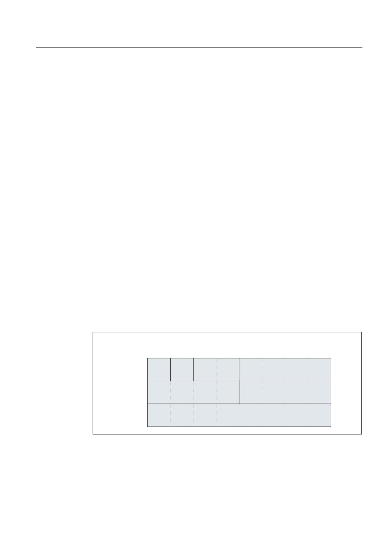
Flexible NC programming
1.1 Variables
$A_DLR
:
Link variable for REAL data format (8 bytes)
Data type:
REAL
Range of values:
±(2.2*10-308 … 1.8*10+308)
<index>
:
Address index in bytes, counted from the start of the link variable memory
Data type:
INT
Range of values:
0 - MAX_INDEX
Note
• MAX_INDEX is calculated from the parameterized size
of the link variables memory: MAX_INDEX =
(MD18700 $MN_MM_SIZEOF_LINKVAR_DATA) - 1
• Only indices may be programmed, so that the bytes
addressed in the link variables memory are located on
a data format limit ⇒
Index = n * bytes, where n = 0, 1, 2, etc.
- $A_DLB[i]: i = 0, 1, 2, etc.
- $A_DLW[i]: i = 0, 2, 4, etc.
- $A_DLD[i]: i = 0, 4, 8, etc.
- $A_DLR[i]: i = 0, 8, 16, etc.
Example
An automation system contains 2 NCUs (NCU1 and NCU2). Machine axis AX2 is connected
to NCU1. It is traversed as a link axis of NCU2.
NCU1 writes the actual current value ($VA_CURR) of axis AX2 cyclically to the link variables
memory. NCU2 reads the actual current value transmitted via link communication cyclically
and displays alarm 61000 if the limit value is exceeded.
The data structure in the link variables memory is illustrated in the following figure. The
actual current value is transmitted in the REAL value.
/LQN YDULDEOHV PHPRU\
0'
01B00B6,=(2)B/,1.9$5B'$7$
,QGH[
%<7(
%<7(
:25'
':25'
':25'
':25'
5(
$/
Job Planning
Programming Manual, 03/2010, 6FC5398-2BP20-1BA0
21
Flexible NC programming
1.1 Variables
NCU1
NCU1 uses link variable $A_DLR[ 16 ] to write the actual current value of axis AX2 to the link
variables memory cyclically in the interpolation cycle in a static synchronized action.
Program code
N111 IDS=1 WHENEVER TRUE DO $A_DLR[16]=$VA_CURR[AX2]
NCU2
NCU2 uses link variable $A_DLR[ 16 ] to read the actual current value of axis AX2 from the
link variables memory cyclically in the interpolation cycle in a static synchronized action. If
the actual current value is greater than 23.0 A, alarm 61000 is displayed.
Program code
N222 IDS=1 WHEN $A_DLR[16] > 23.0 DO SETAL(61000)
1.1.5
Definition of user variables (DEF)
Function
The DEF command is used to define user-specific variables and assign values to them. To set
them apart from system variables, these are called user-defined variables or user variables
(user data).
According to range of validity (in other words, the range in which the variable is visible) there
are the following categories of user variable:
● Local user variables (LUD)
Local user variables (LUD) are variables defined in a part program which is not the main
program at the time of execution. They are created when the part program is called and
deleted at the end of the part program or when the NC is reset. Local user variables can
only be accessed within the part program in which they are defined.
● Program-global user variables (PUD)
Program-global user variables (PUD) are user variables defined in a part program used
as the main program. They are created when the part program starts up and deleted at
the end of the part program or when the NC is reset. It is possible to access PUD in the
main program and in all subprograms of the main program.
● Global user variables (GUD)
Global user variables (GUD) are NC- or channel-global variables which are defined in a
data block (SGUD, MGUD, UGUD, GUD4 to GUD9) and are retained following shutdown
and restart. GUD can be accessed in all part programs.
Job Planning
22
Programming Manual, 03/2010, 6FC5398-2BP20-1BA0
Flexible NC programming
1.1 Variables
User variables must be defined before they can be used (read/write). The following rules
must be observed in this context:
● GUD have to be defined in a definition file, e.g. _N_DEF_DIR/_M_SGUD_DEF.
● PUD and LUD have to be defined in a definition section of the part program.
● The data must be defined in a dedicated block.
● Only one data type may be used for each data definition.
● A number of variables of the same data type can be defined for each data definition.
Syntax
DEF <range> <type> <PP_stop> <init_time> <phys_unit> <limit_values>
<access_rights> <name>[<value_1>,<value_2>,<value_3>]=<init_value>
Meaning
DEF:
Command for defining GUD, PUD, LUD user variables
<range>
:
Range of validity, only relevant for GUD:
NCK:
NC-global user variable
CHAN:
Channel-global user variable
<type>
:
Data type:
INT:
Integer with sign
REAL:
Real number (LONG REAL to IEEE)
BOOL:
Truth value TRUE (1)/FALSE (0)
CHAR:
ASCII character
STRING[<MaxLength>]:
Character string of a defined length
AXIS:
Axis/spindle identifier
FRAME:
Geometric data for a static coordinate
transformation
<PP_stop>
:
Preprocessing stop, only relevant for GUD (optional)
SYNR:
Preprocessing stop while reading
SYNW:
Preprocessing stop while writing
SYNRW:
Preprocessing stop while reading/writing
<init_time>
:
Point in time at which the variable is reinitialized (optional)
INIPO:
Power On
INIRE:
End of main program, NC reset or Power On
INICF:
NewConfig or end of main program, NC reset or
Power On
PRLOC:
End of main program, NC reset following local
change or Power On
<phys_unit>:
Physical unit (optional)
PHU <unit>:
Job Planning
Programming Manual, 03/2010, 6FC5398-2BP20-1BA0
23
Flexible NC programming
1.1 Variables
<limit values>
:
Lower and upper limit value (optional)
LLI <limit value>:
Lower limit value (lower limit)
ULI <limit value>:
Upper limit value (upper limit)
<access rights>
:
Access rights for reading/writing GUD via part program or OPI
(optional)
APRP <protection level>: Read: Part program
APWP <protection level>: Write: Part program
APRB <protection level>: Read: OPI
APWB <protection level>: Write: OPI
Protection level Range of values: 0 ... 7
<name>:
Name of variable
Note
• A maximum of 31 characters
• The first two characters must be a letter and/or an underscore.
• The $ sign is reserved for system variables and must not be
used.
[<value_1>,
Specification of array sizes for 1- to max. 3-dimensional array
<value_2>,
<value_3>]:
variables (optional)
<init_value>:
Initialization value (optional)
Examples
Example 1: Definition of user variables in the data block for machine manufacturers
Program code
%_N_MGUD_DEF
; GUD block: Machine manufacturer
$PATH=/_N_DEF_DIR
DEF CHAN REAL PHU 24 LLI 0 ULI 10 STROM_1, STROM_2
; Description
; Definition of two GUD items: STROM_1, STROM_2
; Range of validity: Throughout the channel
; Data type: REAL
; PP stop: Not programmed => default value = no PP stop
; Physical unit: 24 = [A]
; Limit values: low = 0.0, high = 10.0
; Access rights: Not programmed => default value = 7 = key-operated switch position 0
; Initialization value: Not programmed => default value = 0.0
DEF NCK REAL PHU 13 LLI 10 APWP 3 APRP 3 APWB 0 APRB 2 ZEIT_1=12, ZEIT_2=45
; Description
; Definition of two GUD items: ZEIT_1, ZEIT_2
; Range of validity: Throughout the NCK
; Data type: REAL
Job Planning
24
Programming Manual, 03/2010, 6FC5398-2BP20-1BA0
Flexible NC programming
1.1 Variables
Program code
; PP stop: Not programmed => default value = no PP stop
; Physical unit: 13 = [s]
; Limit values: low = 10.0, high = not programmed => upper definition range limit
; Access rights:
;
Part program: Write/read = 3 = end user
;
OPI: Write = 0 = Siemens, read = 3 = end user
; Initialization value: ZEIT_1 = 12.0, ZEIT_2 = 45.0
DEF NCK APWP 3 APRP 3 APWB 0 APRB 3 STRING[5] GUD5_NAME = "COUNTER"
; Description
; Definition of one GUD item: GUD5_NAME
; Range of validity: Throughout the NCK
; Data type: STRING, max. 5 characters
; PP stop: Not programmed => default value = no PP stop
; Physical unit: Not programmed => default value = 0 = no phys. unit
; Limit values: Not programmed => definition range limits: low = 0, high = 255
; Access rights:
;
Part program: Write/read = 3 = end user
;
OPI: Write = 0 = Siemens, read = 3 = end user
; Initialization value: "COUNTER"
M30
Example 2: Program-global and program-local user variables (PUD/LUD)
Program code
Comment
PROC MAIN
; Main program
DEF INT VAR1
; PUD definition
SUB2
; Subprogram call
M30
Job Planning
Programming Manual, 03/2010, 6FC5398-2BP20-1BA0
25
Flexible NC programming
1.1 Variables
Program code
Comment
PROC SUB2
; Subprogram SUB2
DEF INT VAR2
; LUD DEFINITION
IF (VAR1==1)
; Read PUD
VAR1=VAR1+1
; Read and write PUD
VAR2=1
; Write LUD
ENDIF
SUB3
; Subprogram call
M17
Program code
Comment
PROC SUB3
; Subprogram SUB3
IF (VAR1==1)
; Read PUD
VAR1=VAR1+1
; Read and write PUD
VAR2=1
; Error: LUD from SUB2 not known
ENDIF
M17
Example 3: Definition and use of user variables of data type AXIS
Program code
Comment
DEF AXIS ABSCISSA
; 1st geometry axis
DEF AXIS SPINDLE
; Spindle
IF ISAXIS(1) == FALSE GOTOF CONTINUE
ABSCISSA = $P_AXN1
CONTINUE:
SPINDLE=(S1)
1st spindle
OVRA[SPINDLE]=80
; Spindle override = 80%
SPINDLE=(S3)
3rd spindle
Job Planning
26
Programming Manual, 03/2010, 6FC5398-2BP20-1BA0

Flexible NC programming
1.1 Variables
General conditions
Global user variables (GUD)
In the context of the definition of global user variables (GUD), the following machine data has
to be taken into account:
No.
Identifier: $MN_
Meaning
11140
GUD_AREA_ SAVE_TAB
Additional save for GUD blocks
18118 1)
MM_NUM_GUD_MODULES
No. of GUD files in the active file system
18120 1)
MM_NUM_GUD_NAMES_NCK
No. of global GUD names
18130 1)
MM_NUM_GUD_NAMES_CHAN
No. of channel-specific GUD names
18140 1)
MM_NUM_GUD_NAMES_AXIS
No. of axis-specific GUD names
18150 1)
MM_GUD_VALUES_MEM
Memory location for global GUD values
18660 1)
MM_NUM_SYNACT_GUD_REAL
No. of configurable GUD of the REAL data type
18661 1)
MM_NUM_SYNACT_GUD_INT
No. of configurable GUD of the INT data type
18662 1)
MM_NUM_SYNACT_GUD_BOOL
No. of configurable GUD of the BOOL data type
18663 1)
MM_NUM_SYNACT_GUD_AXIS
No. of configurable GUD of the AXIS data type
18664 1)
MM_NUM_SYNACT_GUD_CHAR
No. of configurable GUD of the CHAR data type
18665 1)
MM_NUM_SYNACT_GUD_STRING
No. of configurable GUD of the STRING data type
1)
Not available for SINUMERIK 828D.
Program-global user variables (PUD)
NOTICE
Visibility of program-local user variables (PUD)
Program-local user variables (PUD) defined in the main program will only be visible in
subprograms if the following machine data is set:
MD11120 $MN_LUD_EXTENDED_SCOPE = 1
If MD11120 = 0 the program-local user variables defined in the main program will only be
visible in the main program.
Cross-channel use of an NCK-global user variable of the AXIS data type
An NCK-global user variable of the AXIS data type initialized during definition in the block
with an axis identifier can then only be used in other NC channels if the axis has the same
channel axis number in these channels.
If this is not the case, the variable has to be loaded at the start of the part program or, as in
the following example, the AXNAME(...) function has to be used.
Program code
Comment
DEF NCK STRING[5] ACHSE="X"
; Definition in the data block
N100 AX[AXNAME(ACHSE)]=111 G00
; Use in the part program
Job Planning
Programming Manual, 03/2010, 6FC5398-2BP20-1BA0
27
Flexible NC programming
1.1 Variables
1.1.6
Redefinition of system variables, user variables, and NC language commands
(REDEF)
Function
The REDEF command can be used to change system variable, user variable and NC language
command attributes. A fundamental condition of redefinition is that it has to post-date the
corresponding definition.
Multiple attributes cannot be changed simultaneously during redefinition. A separate REDEF
operation has to be programmed for each attribute to be changed.
If two or more concurrent attribute changes are programmed, the last change is always
active.
Redefinable attributes
See "Overview of definable and redefinable attributes (Page 43)".
Local user variables (PUD/LUD)
Redefinitions are not permitted for local user variables (PUD/LUD).
Syntax
REDEF <name> <PP_stop>
REDEF <name> <phys_unit>
REDEF <name> <limit_values>
REDEF <name> <access_rights>
REDEF <name> <init_time>
REDEF <name> <init_time> <init_value>
Significance
REDEF:
Command for the redefinition of a specific system variable, user
variable, and NC language command attribute
<name>:
Name of a predefined variable or an NC language command
<PP stop>
:
Preprocessing stop
SYNR:
Preprocessing stop while reading
SYNW:
Preprocessing stop while writing
SYNRW:
Preprocessing stop while reading/writing
Job Planning
28
Programming Manual, 03/2010, 6FC5398-2BP20-1BA0
Flexible NC programming
1.1 Variables
<phys_unit>
:
Physical unit
PHU <unit>:
See "Attribute: Physical unit (PHU) (Page 35)"
Note
Cannot be redefined for:
• System variables
• Global user data (GUD)
• Data types: BOOL, AXIS, STRING, FRAME
<limit values>:
Lower and/or upper limit value
LLI <limit value>:
Lower limit value (lower limit)
ULI <limit value>:
Upper limit value (upper limit)
See "Attribute: Limit values (LLI, ULI) (Page 34)"
Note
Cannot be redefined for:
• System variables
• Global user data (GUD)
• Data types: BOOL, AXIS, STRING, FRAME
<access rights>:
Access rights for reading/writing via part program or OPI
APX <protection level>:
Execute: NC language element
APRP <protection level>: Read: Part program
APWP <protection level>: Write: Part program
APRB <protection level>: Read: OPI
APWB <protection level>: Write: OPI
Protection level Range of values: 0 to 7
See "Attribute: Access rights (APR, APW, APRP, APWP, APRB,
APWB) (Page 38)"
<init_time>
:
Point in time at which the variable is reinitialized
INIPO:
POWER ON
INIRE:
End of main program, NC reset or POWER ON
INICF:
NewConfig or end of main program, NC reset or
POWER ON
PRLOC:
End of main program, NC reset following local
change or POWER ON
See "Attribute: Initialization value (Page 30)"
<init_value>:
Initialization value
When redefining the initialization value, an initialization time always
has to be specified also (see <init_time>).
See "Attribute: Initialization value (Page 30)"
Note
Cannot be redefined for:
• System variables, with the exception of setting data
Job Planning
Programming Manual, 03/2010, 6FC5398-2BP20-1BA0
29
Flexible NC programming
1.1 Variables
Example
Redefinitions of system variable $TC_DPC1 in the data block for machine manufacturers
Program code
%_N_MGUD_DEF
; GUD block: Machine manufacturer
$PATH=/_N_DEF_DIR
REDEF $TC_DPC1 APWB 2 APWP 3
REDEF $TC_DPC1 PHU 21
REDEF $TC_DPC1 LLI 0 ULI 200
REDEF $TC_DPC1 INIPO (100, 101, 102, 103)
; Description
;
Write access right: OPI = protection level 2, part program = protection level 3
;
Note
;
When using ACCESS files the redefinition of access rights has to be moved from
; _N_MGUD_DEF to _N_MACCESS_DEF.
; Physical unit = [ % ]
; Limit values: lower = 0, upper = 200
; The array variable is initialized with the 4 values at POWER ON.
M30
General conditions
Granularity
A redefinition is always applied to the entire variable which is uniquely identified by its name.
Array variables do not, for example, support the assignment of different attributes to
individual array elements.
1.1.7
Attribute: Initialization value
Definition (DEF) of user variables
During definition an initialization value can be preassigned for the following user variables:
● Global user variables (GUD)
● Program-global user variables (PUD)
● Local user variables (LUD)
Job Planning
30
Programming Manual, 03/2010, 6FC5398-2BP20-1BA0
Flexible NC programming
1.1 Variables
Redefinition (REDEF) of system and user variables
During redefinition an initialization value can be preassigned for the following variables:
● System data
- Setting data
● User data
- R-parameters
- Synchronized action variables ($AC_MARKER, $AC_PARAM, $AC_TIMER)
- Synchronized action GUD (SYG_xy[ ], where x=R, I, B, A, C, S and y=S, M, U, 4 to 9)
- EPS parameters
- Tool data OEM
- Magazine data OEM
- Global user variables (GUD)
Reinitialization time
During redefinition a point in time can be specified at which the variable should be
reinitialized, i.e. reset to the initialization value.
● INIPO (POWER ON)
The variable is reinitialized at POWER ON.
● INIRE (reset)
The variable is reinitialized on NC reset, mode group reset, at the end of the part program
(M02/M30) or at POWER ON.
● INICF (NewConfig)
The variable is reinitialized on a NewConf request via the HMI, with part program
command NEWCONFIG or on an NC reset, mode group reset, at the end of the part program
(M02/M30) or at POWER ON.
● PRLOC (program-local change)
The variable is only reinitialized on an NC reset, mode group reset or at the end of the
part program (M02/M30) if it has changed during the current part program.
The PRLOC attribute may only be changed in conjunction with programmable setting data
(see the table below).
Job Planning
Programming Manual, 03/2010, 6FC5398-2BP20-1BA0
31

Flexible NC programming
1.1 Variables
Table 1- 1
Programmable setting data
Number
Identifier
G command 1)
SF
42000
$SC_THREAD_START_ANGLE
42010
$SC_THREAD_RAMP_DISP
DITS/DITE
PDELAYON
42400
$SA_PUNCH_DWELLTIME
SETMS
42800
$SA_SPIND_ASSIGN_TAB
G25
43210
$SA_SPIND_MIN_VELO_G25
G26
43220
$SA_SPIND_MAX_VELO_G26
LIMS
43230
$SA_SPIND_MAX_VELO_LIMS
FPRAON
43300
$SA_ASSIGN_FEED_PER_REV_SOURCE
G26
43420
$SA_WORKAREA_LIMIT_PLUS
G25
43430
$SA_WORKAREA_LIMIT_MINUS
FXST
43510
$SA_FIXED_STOP_TORQUE
FXSW
43520
$SA_FIXED_STOP_WINDOW
OSP1
43700
$SA_OSCILL_REVERSE_POS1
OSP2
43710
$SA_OSCILL_REVERSE_POS2
OST1
43720
$SA_OSCILL_DWELL_TIME1
OST2
43730
$SA_OSCILL_DWELL_TIME2
FA
43740
$SA_OSCILL_VELO
OSNSC
43750
$SA_OSCILL_NUM_SPARK_CYCLES
OSE
43760
$SA_OSCILL_END_POS
OSCTRL
43770
$SA_OSCILL_CTRL_MASK
OS
43780
$SA_OSCILL_IS_ACTIVE
OSB
43790
$SA_OSCILL_START_POS
1) This G command is used to address the setting data.
General conditions
Initialization value: Global user variables (GUD)
● Only INIPO (POWER ON) can be defined as the initialization time for global user variables
(GUD) with the NCK range of validity.
● In addition to INIPO (POWER ON), INIRE (reset) or INICF (NewConfig) can be defined as
the initialization time for global user variables (GUD) with the CHAN range of validity.
● In the case of global user variables (GUD) with the CHAN range of validity and INIRE (reset)
or INICF (NewConfig) initialization time, for an NC reset, mode group reset and
NewConfig, the variables are only reinitialized in the channels in which the named events
were triggered.
Job Planning
32
Programming Manual, 03/2010, 6FC5398-2BP20-1BA0
Flexible NC programming
1.1 Variables
Initialization value: FRAME data type
It is not permitted to specify an initialization value for variables of the FRAME data type.
Variables of the FRAME data type are initialized implicitly and always with the default frame.
Initialization value: CHAR data type
For variables of the CHAR data type, instead of the ASCII code (0...255), the corresponding
ASCII character can be programmed in quotation marks, e.g. "A".
Initialization value: STRING data type
In the case of variables of the STRING data type, the character string must be enclosed in
quotation marks, e.g
= "MACHINE_1"
Initialization value: AXIS data type
In the case of variables of the AXIS data type, for an extended address notation, the axis
identifier must be enclosed in brackets, e.g
=(X3).
Initialization value: System variable
For system variables, redefinition cannot be used to define user-specific initialization values.
The initialization values for the system variables are specified by the system and cannot be
changed. However, redefinition can be used to change the point in time (INIRE, INICF) at
which the system variable is reinitialized.
Implicit initialization value: AXIS data type
For variables of the AXIS data type the following implicit initialization value is used:
● System data: "First geometry axis"
● Synchronized action GUD (Designation: SYG_A*), PUD, LUD:
Axis identifier from machine data: MD20082 $MC_AXCONF_CHANAX_DEFAULT_NAME
Implicit initialization value: Tool and magazine data
Initialization values for tool and magazine data can be defined using the following machine
data: MD17520 $MN_TOOL_DEFAULT_DATA_MASK
NOTICE
Synchronization
The synchronization of events triggering the reinitialization of a global variable when this
variable is read in a different location is the sole responsibility of the user/machine
manufacturer.
Job Planning
Programming Manual, 03/2010, 6FC5398-2BP20-1BA0
33
Flexible NC programming
1.1 Variables
1.1.8
Attribute: Limit values (LLI, ULI)
An upper and a lower limit of the definition range can only be defined for the following data
types:
● INT
● REAL
● CHAR
Definition (DEF) of user variables: Limit values and implicit initialization values
If no explicit initialization value is defined when defining a user variable of one of the above
data types, the variable is set to the data type's implicit initialization value.
● INT: 0
● REAL: 0.0
● CHAR: 0
If the implicit initialization value is outside the definition range specified by the programmed
limit values, the variable is initialized with the limit value which is closest to the implicit
initialization value:
● Implicit initialization value < lower limit value (LLI) ⇒
initialization value = lower limit value
● Implicit initialization value > upper limit value (ULI) ⇒
initialization value = upper limit value
Examples:
Program code
Comment
DEF REAL GUD1
;
Lower limit value = definition range limit
;
Upper limit value = definition range limit
;
No initialization value programmed
;
=> Implicit initialization value = 0.0
DEF REAL LLI 5.0 GUD2
;
Lower limit value = 5.0
;
Upper limit value = definition range limit
;
=> Initialization value = 5.0
DEF REAL ULI -5 GUD3
;
Lower limit value = definition range limit
;
Upper limit value = -5.0
;
=> Initialization value = -5.0
Job Planning
34
Programming Manual, 03/2010, 6FC5398-2BP20-1BA0

Flexible NC programming
1.1 Variables
Redefinition (REDEF) of user variables: Limit values and current actual values
If, when the limit values of a user variable are redefined, they change to the extent that the
current actual value is outside the new definition range, an alarm will be issued and the limit
values will be rejected.
Note
Redefinition (REDEF) of user variables
When the limit values of a user variable are redefined, care must be taken to ensure that the
following values are changed consistently:
• Limit values
• Actual value
• Initialization value on redefinition and automatic reinitialization on the basis of INIPO,
INIRE or INICF
1.1.9
Attribute: Physical unit (PHU)
A physical unit can only be specified for variables of the following data types:
● INT
● REAL
Programmable physical units (PHU)
The physical unit is specified as fixed point number: PHU <unit>
The following physical units can be programmed:
<unit>
Meaning
Physical unit
0
Not a physical unit
-
1
Linear or angular position 1)2)
[ mm ], [ inch ], [ degree ]
2
Linear position2)
[ mm ], [ inch ]
3
Angular position
[ degree ]
4
Linear or angular velocity 1)2)
[ mm/min ], [ inch/min ], [ rpm ]
5
Linear velocity2)
[ mm/min ]
6
Angular velocity
[ rpm ]
7
Linear or angular acceleration 1)2)
[ m/s2 ], [ inch/s2 ], [ rev/s2 ]
8
Linear acceleration2)
[ m/s2 ], [ inch/s2 ]
9
Angular acceleration
[ rev/s2 ]
10
Linear or angular jerk 1)2)
[ m/s3 ], [ inch/s3 ], [ rev/s3 ]
Job Planning
Programming Manual, 03/2010, 6FC5398-2BP20-1BA0
35
Flexible NC programming
1.1 Variables
<unit>
Meaning
Physical unit
11
Linear jerk2)
[ m/s3 ], [ inch/s3 ]
12
Angular jerk
[ rev/s3 ]
13
Time
[ s ]
14
Position controller gain
[ 16.667/s ]
15
Revolutional feedrate 2)
[ mm/rev ], [ inch/rev ]
16
Temperature compensation 1)2)
[ mm ], [ inch ]
18
Force
[ N ]
19
Mass
[ kg ]
20
Moment of inertia 3)
[ kgm2 ]
21
Percent
[ % ]
22
Frequency
[ Hz ]
23
Voltage
[ V ]
24
Current
[ A ]
25
Temperature
[ °C ]
26
Angle
[ degree ]
27
KV
[ 1000/min ]
28
Linear or angular position 3)
[ mm ], [ inch ], [ degree ]
29
Cutting rate 2)
[ m/min ], [ feet/min ]
30
Peripheral speed 2)
[ m/s], [ feet/s ]
31
Resistance
[ ohm ]
32
Inductance
[ mH ]
33
Torque 3)
[ Nm ]
34
Torque constant 3)
[ Nm/A ]
35
Current controller gain
[ V/A ]
36
Speed controller gain 3)
[ Nm/(rad*s) ]
37
Speed
[ rpm ]
42
Power
[ kW ]
43
Current, low
[ μA ]
46
Torque, low 3)
[ μNm ]
48
Per mil
-
49
-
[ Hz/s ]
65
Flow rate
[ l/min ]
66
Pressure
[ bar ]
67
Volume 3)
[ cm3 ]
68
Controlled-system gain 3)
[ mm/(V*min) ]
69
Force controller controlled-system gain
[ N/V ]
155
Thread lead 3)
[ mm/rev ], [ inch/rev ]
156
Change in thread lead 3)
[ mm/rev / rev ], [ inch/rev / rev ]
Job Planning
36
Programming Manual, 03/2010, 6FC5398-2BP20-1BA0
Flexible NC programming
1.1 Variables
<unit>
Meaning
Physical unit
1) The physical unit is dependent on the axis type: linear or rotary axis.
2) System of units changeover
G70/G71(inch/metric)
After changing over the basic system (MD10240 $MN_SCALING_SYSTEM_IS_METRIC) with
G70/G71, for read/write operations to system and user variables involving a length, then the values
are not converted (actual value, default value and limit values)
G700/G710(inch/metric)
After changing over the basic system (MD10240 $MN_SCALING_SYSTEM_IS_METRIC) with
G700/G710, for read/write operations to system and user variables involving a length, then the values
are converted (actual value, default value and limit values)
3) The variable is not converted to the NC's current measuring system (inch/metric) automatically.
Conversion is the sole responsibility of the user/machine manufacturer.
Note
Level overflow due to format conversion
The internal storage format for all user variables (GUD/PUD/LUD) with physical units of
length is metric. Excessive use of these types of variable in the NCK's main run, e.g in
synchronized actions, can lead to a CPU time overflow at interpolation level when the
measuring system is switched over, generating alarm 4240.
NOTICE
Compatibility of units
When using variables (assignment, comparison, calculation, etc.) the compatibility of the
units involved is not checked. Should conversion be required, this is the sole responsibility
of the user/machine manufacturer.
Job Planning
Programming Manual, 03/2010, 6FC5398-2BP20-1BA0
37

Flexible NC programming
1.1 Variables
1.1.10
Attribute: Access rights (APR, APW, APRP, APWP, APRB, APWB)
The following protection levels, which have to be specified during programming, correspond
to the access rights:
Access right
Protection level
System password
0
Machine manufacturer password
1
Service password
2
End user password
3
Key-operated switch position 3
4
Key-operated switch position 2
5
Key-operated switch position 1
6
Key-operated switch position 0
7
Definition (DEF) of user variables
Access rights (APR.../APW...) can be defined for the following variables:
● Global user data (GUD)
Redefinition (REDEF) of system and user variables
Access rights (APR.../APW...) can be redefined for the following variables:
● System data
- Machine data
- Setting data
- FRAME
- Process data
- Leadscrew error compensation data (LEC)
- Sag compensation (CEC)
- Quadrant error compensation (QEC)
- Magazine data
- Tool data
- Protection zones
- Toolholder, with orientation capability
- Kinematic chains
- 3D protection zones
- Working area limitation
- ISO tool data
Job Planning
38
Programming Manual, 03/2010, 6FC5398-2BP20-1BA0
Flexible NC programming
1.1 Variables
● User data
- R-parameters
- Synchronized action variables ($AC_MARKER, $AC_PARAM, $AC_TIMER)
- Synchronized action GUD (SYG_xy[ ], where x=R, I, B, A, C, S and y=S, M, U, 4 to 9)
- EPS parameters
- Tool data OEM
- Magazine data OEM
- Global user variables (GUD)
Note
During redefinition the access right can be freely assigned to a variable between the
lowest protection level 7 and the dedicated protection level, e.g. 1 (machine
manufacturer).
Redefinition (REDEF) of NC language commands
The access or execution right (APX) can be redefined for the following NC language
commands:
● G functions/Preparatory functions
References:
/PG/ Programming Manual, Fundamentals; Chapter: G functions/Preparatory functions
● Predefined functions
References:
/PG/ Programming Manual, Fundamentals; Chapter: Predefined functions
● Predefined subprogram calls
References:
/PG/ Programming Manual, Fundamentals; Chapter: Predefined subprogram calls
● DO operation with synchronized actions
● Cycles program identifier
The cycle must be saved in a cycle directory and must contain a PROC operation.
Job Planning
Programming Manual, 03/2010, 6FC5398-2BP20-1BA0
39
Flexible NC programming
1.1 Variables
Access rights in relation to part programs and cycles (APRP, APWP)
The various access rights facilitate the following with regard to access in a part program or
cycle:
●
APRP 0/APWP 0
- During part program processing the system password has to be set.
- The cycle has to be stored in the _N_CST_DIR directory (system).
- The execution right must be set to system for the _N_CST_DIR directory in MD11160
$MN_ACCESS_EXEC_CST.
●
APRP 1/APWP 1 or APRP 2/APWP 2
- During part program processing the machine manufacturer or service password has to
be set.
- The cycle has to be stored in the _N_CMA_DIR (machine manufacturer) or
_N_CST_DIR (system) directory.
- The execution rights must be set to at least machine manufacturer for the
_N_CMA_DIR or _N_CST_DIR directories in machine data MD11161
$MN_ACCESS_EXEC_CMA or MD11160 $MN_ACCESS_EXEC_CST respectively.
●
APRP 3/APWP 3
- During part program processing the end user password has to be set.
- The cycle has to be stored in the _N_CUS_DIR (user), _N_CMA_DIR or _N_CST_DIR
directory.
- The execution rights must be set to at least end user for the _N_CUS_DIR,
_N_CMA_DIR or _N_CST_DIR directories in machine data MD11162
$MN_ACCESS_EXEC_CUS, MD11161 $MN_ACCESS_EXEC_CMA or MD11160
$MN_ACCESS_EXEC_CST respectively.
●
APRP 4...7/APWP 4...7
- During part program processing the key-operated switch must be set to 3 ... 0.
- The cycle has to be stored in the _N_CUS_DIR, _N_CMA_DIR or _N_CST_DIR
directory.
- The execution rights must be set to at least the corresponding key-operated switch
position for the _N_CUS_DIR, _N_CMA_DIR or _N_CST_DIR directories in machine
data MD11162 $MN_ACCESS_EXEC_CUS, MD11161 $MN_ACCESS_EXEC_CMA
or MD11160 $MN_ACCESS_EXEC_CST respectively.
Job Planning
40
Programming Manual, 03/2010, 6FC5398-2BP20-1BA0
Flexible NC programming
1.1 Variables
Access rights in relation to OPI (APRB, APWB)
The access rights (APRB, APWB) restrict access to system and user variables via the OPI
equally for all system components (HMI, PLC, external computers, EPS services, etc.).
Note
Local HMI access rights
When changing access rights to system data, care must be taken to ensure that such
changes are consistent with the access rights defined using HMI mechanisms.
APR/APW access attributes
For compatibility reasons, attributes APR and APW are implicitly mapped to the attributes APRP /
APRB and APWP / APWB:
● APR x ⇒ APRP x APRB x
● APW y ⇒ APWP y APWB y
Setting access rights using ACCESS files
When using ACCESS files to assign access rights, redefinitions of access rights for system
data, user data, and NC language commands may only continue to be programmed in these
ACCESS files. Global user data (GUD) is an exception. For this data, access rights have to
continue to be redefined (if this appears necessary) in the corresponding definition files.
For continuous access protection, the machine data for the execution rights and the access
protection for the corresponding directories have to be modified consistently.
In principle, the procedure is as follows:
● Creation of the necessary definition files:
- _N_DEF_DIR/_N_SACCESS_DEF
- _N_DEF_DIR/_N_MACCESS_DEF
- _N_DEF_DIR/_N_UACCESS_DEF
● Setting of the write right for the definition files to the value required for redefinition:
- MD11170 $MN_ACCESS_WRITE_SACCESS
- MD11171 $MN_ACCESS_WRITE_MACCESS
- MD11172 $MN_ACCESS_WRITE_UACCESS
Job Planning
Programming Manual, 03/2010, 6FC5398-2BP20-1BA0
41
Flexible NC programming
1.1 Variables
● For access to protected elements from cycles, the execution and write rights for cycle
directories _N_CST_DIR, _N_CMA_DIR, and _N_CST_DIR have to be modified.
Execution rights
- MD11160 $MN_ACCESS_EXEC_CST
- MD11161 $MN_ACCESS_EXEC_CMA
- MD11162 $MN_ACCESS_EXEC_CUS
Write rights
- MD11165 $MN_ACCESS_WRITE_CST
- MD11166 $MN_ACCESS_WRITE_CMA
- MD11167 MN_ACCESS_WRITE_CUS
The execution right has to be set to at least the same protection level as the highest
protection level of the element used.
The write right must be set to at least the same protection level as the execution right.
● The write rights of the local HMI cycle directories must be set to the same protection level
as the local NC cycle directories.
References
/BAD/ Operating Manual, HMI Advanced,
Chapter: Services operating area > Data administration > Modify properties
Subprogram calls in ACCESS files
To structure access protection further, subprograms (SPF or MPF identifier) can be called in
ACCESS files. The subprograms inherit the execution rights of the calling ACCESS file.
Note
Only access rights can be redefined in the ACCESS files. All other attributes have to
continue to be programmed/redefined in the corresponding definition files.
Job Planning
42
Programming Manual, 03/2010, 6FC5398-2BP20-1BA0
Flexible NC programming
1.1 Variables
1.1.11
Overview of definable and redefinable attributes
The following tables show which attributes can be defined (DEF) and/or redefined (REDEF) for
which data types.
System data
Data type
Init. value
Limit values
Physical unit
Access rights
REDEF
Machine data
---
---
---
REDEF
REDEF
Setting data
---
---
REDEF
FRAME data
---
---
---
REDEF
Process data
---
---
---
REDEF
Leadscrew error comp. (EEC)
---
---
---
REDEF
Sag compensation (CEC)
---
---
---
REDEF
Quadrant error compensation (QEC)
---
---
---
REDEF
Magazine data
---
---
---
REDEF
Tool data
---
---
---
REDEF
Protection zones
---
---
---
REDEF
Toolholder, with orientation capability
---
---
---
REDEF
Kinematic chains
---
---
---
REDEF
3D protection zones
---
---
---
REDEF
Working area limitation
---
---
---
REDEF
ISO tool data
---
---
---
User data
Data type
Init. value
Limit values
Physical unit
Access rights
REDEF
REDEF
REDEF
REDEF
R-parameters
REDEF
REDEF
REDEF
REDEF
Synchronized action variable ($AC_...)
REDEF
REDEF
REDEF
REDEF
Synchronized action GUD (SYG_...)
REDEF
REDEF
REDEF
REDEF
EPS parameters
REDEF
REDEF
REDEF
REDEF
Tool data OEM
REDEF
REDEF
REDEF
REDEF
Magazine data OEM
DEF/REDEF
DEF
DEF
DEF/REDEF
Global user variables (GUD)
DEF
DEF
DEF
Local user variables (PUD/LUD)
---
Job Planning
Programming Manual, 03/2010, 6FC5398-2BP20-1BA0
43

Flexible NC programming
1.1 Variables
1.1.12
Definition and initialization of array variables (DEF, SET, REP)
Function
A user variable can be defined as a 1- up to a maximum of a 3-dimensional array.
●
1-dimensional: DEF <data type> <variable name>[<n>]
●
2-dimensional: DEF <data type> <variable name>[<n>,<m>]
●
3-dimensional: DEF <data type> <variable name>[<n>,<m>,<o>]
Note
STRING data type user variables can be defined as up to a maximum of 2-dimensional
arrays.
Data types
User variables can be defined as arrays for the following data types: BOOL, CHAR, INT,
REAL, STRING, AXIS, FRAME
Assignment of values to array elements
Values can be assigned to array elements at the following points in time:
● During array definition (initialization values)
● During program execution
Values can be assigned by means of:
● Explicit specification of an array element
● Explicit specification of an array element as a starting element and specification of a
value list (SET)
● Explicit specification of an array element as a starting element and specification of a
value and the frequency at which it is repeated (REP)
Note
FRAME data type user variables cannot be assigned initialization values.
Syntax (DEF)
DEF <data type> <variable name>[<n>,<m>,<o>]
DEF STRING[<string length>] <variable name>[<n>,<m>]
Job Planning
44
Programming Manual, 03/2010, 6FC5398-2BP20-1BA0
Flexible NC programming
1.1 Variables
Syntax (DEF...=SET...)
Using a value list:
● During definition:
DEF <data type> <variable name>[<n>,<m>,<o>]=SET(<value1>,<value2>, etc.)
Equivalent to:
DEF <data type> <variable name>[<n>,<m>,<o>]=(<value1>,<value2>, etc.)
Note
SET does not have to be specified for initialization via a value list.
● During value assignment:
<variable name>[<n>,<m>,<o>]=SET(<VALUE1>,<value2>, etc.)
Syntax (DEF...=REP...)
Using a value with repetition
● During definition:
DEF <data type> <variable name>[<n>,<m>,<o>]=REP(<value>)
DEF <data type> <variable name>[<n>,<m>,<o>]=REP(<value>, <number_array_elements>)
● During value assignment:
<variable name>[<n>,<m>,<o>]=REP(<value>)
DEF <data type> <variable name>[<n>,<m>,<o>]=REP(<value>,<number_array_elements>)
Significance
DEF:
Command to define variables
<data type>:
Data type of variables
Range of values:
• for system variables:
BOOL, CHAR, INT, REAL, STRING, AXIS
• for GUD or LUD variables:
BOOL, CHAR, INT, REAL, STRING, AXIS,
FRAME
<string length>:
Maximum number of characters for a STRING data
type
<variable name>:
Variable name.
[<n>,<m>,<o>]:
Array sizes or array indices
<n>
:
Array size or array index for 1st dimension
Type: INT (for system variables, also AXIS)
Range of values: Max. array size: 65535
Array index: 0 ≤ n ≤ 65534
Job Planning
Programming Manual, 03/2010, 6FC5398-2BP20-1BA0
45
Flexible NC programming
1.1 Variables
<m>
:
Array size or array index for 2nd dimension
Type: INT (for system variables, also AXIS)
Range of values: Max. array size: 65535
Array index: 0 ≤ m ≤ 65534
<o>
:
Array size or array index for 3rd dimension
Type: INT (for system variables, also AXIS)
Range of values: Max. array size: 65535
Array index: 0 ≤ o ≤ 65534
SET:
Value assignment using specified value list
(<value1>,<value2>, etc.):
Value list
REP:
Value assignment using specified <value>
<value>:
Value, which the array elements should be written
when initializing with REP.
<number_array_elements>:
Number of array elements to be written with the
specified <value>. The following apply to the
remaining array elements, dependent on the point in
time:
• initialization when defining the array:
→ Zero is written to the remaining array elements.
• Assignment during program execution:
→ The actual values of the array elements remain
unchanged.
If the parameter is not programmed, all array
elements are written with <value>.
If the parameter equals zero, the following apply
dependent on the point in time:
• initializing when defining the array:
→ All elements are pre-assigned zero
• Assignment during program execution:
→ The actual values of the array elements remain
unchanged.
Job Planning
46
Programming Manual, 03/2010, 6FC5398-2BP20-1BA0
Flexible NC programming
1.1 Variables
Array index
The implicit sequence of the array elements, e.g. in the case of value assignment using SET
or REP, is right to left due to iteration of the array index.
Example: Initialization of a 3-dimensional array with 24 array elements:
DEF INT FELD[2,3,4] = REP(1,24)
FELD[0,0,0] = 1
1st array element
FELD[0,0,1] = 1
2nd array element
FELD[0,0,2] = 1
3rd array element
FELD[0,0,3] = 1
4th array element
FELD[0,1,0] = 1
5th array element
FELD[0,1,1] = 1
6th array element
FELD[0,2,3] = 1
12th array element
FELD[1,0,0] = 1
13th array element
FELD[1,0,1] = 1
14th array element
FELD[1,2,3] = 1
24th array element
corresponding to:
FOR n=0 TO 1
FOR m=0 TO 2
FOR o=0 TO 3
FELD[n,m,o] = 1
ENDFOR
ENDFOR
ENDFOR
Job Planning
Programming Manual, 03/2010, 6FC5398-2BP20-1BA0
47
Flexible NC programming
1.1 Variables
Example: Initializing complete variable arrays
For the actual assignment, refer to the diagram.
Program code
N10 DEF REAL FELD1[10,3]=SET(0,0,0,10,11,12,20,20,20,30,30,30,40,40,40,)
N20 ARRAY1[0,0] = REP(100)
N30 ARRAY1[5,0] = REP(-100)
N40 FELD1[0,0]=SET(0,1,2,-10,-11,-12,-20,-20,-20,-30, , , ,-40,-40,-50,-60,-70)
N50 FELD1[8,1]=SET(8.1,8.2,9.0,9.1,9.2)
$UUD\ LQGH[
1
,QLWLDOL]DWLRQ IRU
1
1
,QLWLDOL]DWLRQ ZLWK
1
1
,QLWLDOL]DWLRQ ZLWK
GHILQLWLRQ
LGHQWLFDO YDOXH
YDULRXV YDOXHV
7KH DUUD\ HOHPHQWV > @ WR
7KH DUUD\ HOHPHQWV > @ WR
>
@ KDYH EHHQ LQLWLDOL]HG
>
@ KDYH EHHQ LQLWLDOL]HG
ZLWK WKH GHIDXOW YDOXH
ZLWK WKH GHIDXOW YDOXH
7KH DUUD\ HOHPHQWV > @ WR
>
@ KDYH QRW EHHQ FKDQJHG
Job Planning
48
Programming Manual, 03/2010, 6FC5398-2BP20-1BA0
Flexible NC programming
1.1 Variables
1.1.13
Definition and initialization of array variables (DEF, SET, REP): Further
Information
Further information (SET)
Initialization during definition
● Starting with the 1st array element, as many array elements are assigned with the values
from the value list as there are elements programmed in the value list.
● A value of 0 is assigned to array elements without explicitly declared values in the value
list (gaps in the value list).
● For variables of the AXIS data type, gaps in the value list are not permitted.
● If the value list contains more values than there are array elements defined, an alarm will
be displayed.
Value assignment in program execution
In the case of value assignment in program execution, the rules described above for
definition apply. The following options are also supported:
● Expressions are also permitted as elements in the value list.
● Value assignment starts with the programmed array index. Values can be assigned
selectively to subarrays.
Example:
Program code
Comments
DEF INT ARRAY[5,5]
; Array definition
ARRAY[0,0]=SET(1,2,3,4,5)
; Value assignment to the first 5 array
elements [0,0] - [0,4]
FELD[0,0]=SET(1,2, , ,5)
; Value assignment with gap to the first
5 array elements [0,0] - [0,4], array
elements[0,2] and [0,3] = 0
ARRAY[2,3]=SET(VARIABLE,4*5.6)
; Value assignment with variable and
expression starting at array index [2,3]:
[2,3] = VARIABLE
[2,4] = 4 * 5.6 = 22.4
Job Planning
Programming Manual, 03/2010, 6FC5398-2BP20-1BA0
49
Flexible NC programming
1.1 Variables
Further information (REP)
initialization during definition
● All or the optionally specified number of array elements are initialized with the specified
value (constant).
● Variables of the FRAME data type cannot be initialized.
Example:
Program code
Comments
DEF REAL varName[10]=REP(3.5,4)
; Initialize array definition and array
elements [0] to [3] with value 3.5.
Value assignment in program execution
In the case of value assignment in program execution, the rules described above for
definition apply. The following options are also supported:
● Expressions are also permitted as elements in the value list.
● Value assignment starts with the programmed array index. Values can be assigned
selectively to subarrays.
Examples:
Program code
Comments
DEF REAL varName[10]
; Array definition
varName[5]=REP(4.5,3)
; Array elements [5] to [7] = 4.5
R10=REP(2.4,3)
; R-parameters R10 to R12 = 2.4
DEF FRAME FRM[10]
; Array definition
FRM[5] = REP(CTRANS (X,5))
; Array elements [5] to [9] = CTRANS(X,5)
Job Planning
50
Programming Manual, 03/2010, 6FC5398-2BP20-1BA0
Flexible NC programming
1.1 Variables
Further information (general)
Value assignments to axial machine data
In principle axial machine data have an array index of the AXIS data type. In the case of
value assignments to an axial item of machine data using SET or REP, this array index is
ignored or not processed.
Example: Value assignment to machine data MD36200 $MA_AX_VELO_LIMIT
$MA_AX_VELO_LIMIT[1,AX1]=SET(1.1, 2.2, 3.3)
Is equivalent to:
$MA_AX_VELO_LIMIT[1,AX1] = 1.1
$MA_AX_VELO_LIMIT[2,AX1] = 2.2
$MA_AX_VELO_LIMIT[3,AX1] = 3.3
NOTICE
Value assignments to axial machine data
In the case of value assignments to axial machine data using SET or REP, the AXIS data type
array index is ignored or not processed.
Memory requirements
Data type
Memory requirement per element
BOOL
1 byte
CHAR
1 byte
INT
4 bytes
REAL
8 bytes
STRING
(string length + 1) bytes
FRAME
∼ 400 bytes, depending on the number of axes
AXIS
4 bytes
Job Planning
Programming Manual, 03/2010, 6FC5398-2BP20-1BA0
51

Flexible NC programming
1.1 Variables
1.1.14
Data types
The following data types are available in the NC:
Data type
Significance
Value Range
INT
Integer with sign
-2147483648 ... +2147483647
REAL
Real number (LONG REAL to IEEE)
±(∼2.2*10-308 … ∼1.8*10+308)
BOOL
Truth value TRUE (1) and FALSE (0)
1, 0
CHAR
ASCII character
ASCII code 0 to 255
STRING
Character string of a defined length
Maximum of 200 characters (no special characters)
AXIS
Axis/spindle identifier
Channel axis identifier
FRAME
Geometric parameters for static coordinate
---
transformation (translation, rotation, scaling,
mirroring)
Implicit data type conversions
The following data type conversions are possible and are performed implicitly during
assignments and parameter transfers:
from ↓/ to →
REAL
INT
BOOL
REAL
x
o
&
INT
x
x
&
BOOL
x
x
x
x : Possible without restrictions
o: Data loss possible due to the range of values being overshot ⇒ alarm;
rounding: decimal place value ≥ 0.5 ⇒ round up, decimal place value < 0.5 ⇒ round down
&: value ≠ 0 ⇒ TRUE, value== 0 ⇒ FALSE
Job Planning
52
Programming Manual, 03/2010, 6FC5398-2BP20-1BA0
Flexible NC programming
1.2 Indirect programming
1.2
Indirect programming
1.2.1
Indirectly programming addresses
Function
When indirectly programming addresses, the extended address (index) is replaced by a
variable with a suitable type.
Note
It is not possible the indirectly program addresses for:
• N (block number)
• L (subprogram)
• Settable addresses
(e.g. X[1] instead of X1 is not permissible)
Syntax
<ADDRESS>[<Index>]
Significance
<ADDRESS>[...]:
Fixed address with extension (index)
<index>:
Index variable, e.g., spindle number, axis,
Examples
Example 1: Indirectly programming a spindle number
Direct programming:
Program code
Comments
S1=300
; Speed in rpm for the spindle number 1.
Indirect programming:
Program code
Comments
DEF INT SPINU=1
; Defining variables, type INT and value assignment.
S[SPINU]=300
; Speed 300 rpm for the spindle, whose number is saved in
the SPINU variable (in this example 1, the spindle with
the number 1).
Job Planning
Programming Manual, 03/2010, 6FC5398-2BP20-1BA0
53

Flexible NC programming
1.2 Indirect programming
Example 2: Indirectly programming an axis
Direct programming:
Program code
Comments
FA[U]=300
; Feed rate 300 for axis "U".
Indirect programming:
Program code
Comments
DEF AXIS AXVAR2=U
; Defining a variable, type AXIS and value assignment.
FA[AXVAR2]=300
; Feed rate of 300 for the axis whose address name is saved
in the variables with the name AXVAR2.
Example 3: Indirectly programming an axis
Direct programming:
Programming
Comments
$AA_MM[X]
; Read probe measured value (MCS) of axis "X".
Indirect programming:
Program code
Comments
DEF AXIS AXVAR3=X
; Defining a variable, type AXIS and value assignment.
$AA_MM[AXVAR3]
; Read probe measured value (MCS) whose name is saved in the
variables AXVAR3.
Example 4: Indirectly programming an axis
Direct programming:
Program code
X1=100 X2=200
Indirect programming:
Program code
Comments
DEF AXIS AXVAR1 AXVAR2
; Defining two type AXIS variables.
AXVAR1=(X1) AXVAR2=(X2)
; Assigning the axis names.
AX[AXVAR1]=100 AX[AXVAR2]=200
; Traversing the axes whose address names are
saved in the variables with the names
AXVAR1 and AXVAR2
Job Planning
54
Programming Manual, 03/2010, 6FC5398-2BP20-1BA0
Flexible NC programming
1.2 Indirect programming
Example 5: Indirectly programming an axis
Direct programming:
Program code
G2 X100 I20
Indirect programming:
Program code
Comments
DEF AXIS AXVAR1=X
; Defining a variable, type AXIS and value
assignment.
G2 X100 IP[AXVAR1]=20
; Indirect programming the center point data for
the axis, whose address name is saved in the
variable with the name AXVAR1.
Example 6: Indirectly programming array elements
Direct programming:
Program code
Comments
DEF INT ARRAY1[4,5]
; Defining array 1
Indirect programming:
Program code
Comments
DEFINE DIM1 AS 4
; For array dimensions, array sizes must be
specified as fixed values.
DEFINE DIM2 AS 5
DEF INT ARRAY[DIM1,DIM2]
ARRAY[DIM1-1,DIM2-1]=5
Example 7: Indirect subprogram call
Program code
Comments
CALL "L" << R10
; Call the program, whose number is located in R10
(string cascading).
Job Planning
Programming Manual, 03/2010, 6FC5398-2BP20-1BA0
55
Flexible NC programming
1.2 Indirect programming
1.2.2
Indirectly programming G codes
Function
Indirect programming of G codes permits cycles to be effectively programmed.
Syntax
G[<group>]=<number>
Meaning
G[...]:
G command with extension (index)
<group>:
Index parameter: G function group
Type: INT
<number>:
Variable for the G code number
Type: INT or REAL
Note
Generally, only G codes that do not determine the syntax can be indirectly programmed.
Only G function group 1 is possible from the G codes that determine the syntax.
The syntax-determining G codes of G function groups 2, 3 and 4 are not possible.
Note
Arithmetic functions are not permitted in the indirect G code programming. If it is necessary
to calculate the G code number, this must be done in a separate part program line before the
indirect G code programming.
Examples
Example 1: Settable zero offset (G function group 8)
Program code
Comment
N1010 DEF INT INT_VAR
N1020 INT_VAR=2
N1090 G[8]=INT_VAR G1 X0 Y0
; G54
N1100 INT_VAR=INT_VAR+1
; G code calculation
N1110 G[8]=INT_VAR G1 X0 Y0
; G55
Job Planning
56
Programming Manual, 03/2010, 6FC5398-2BP20-1BA0
Flexible NC programming
1.2 Indirect programming
Example 2: Level selection (G function group 6)
Program code
Comment
N2010 R10=$P_GG[6]
; read active G function of G function
group 6
N2090 G[6]=R10
References
For information on the G function groups, refer to:
Programming Manual, Fundamentals; Chapter "G function groups"
1.2.3
Indirectly programming position attributes (BP)
Function
Position attributes, e.g. the incremental or absolute programming of the axis position, can be
indirectly programmed as variables in conjunction with the key word BP.
Application
The indirect programming of position attributes is used in replacement cycles, as in this
case, the following advantage exists over programming position attributes as keyword (e.g.
IC, AC, ...):
As a result of the indirect programming as variable, no CASE instruction is required, which
would otherwise branch for all possible position attributes.
Syntax
<POSITIONING COMMAND>[<axis/spindle>]=
BP(<position>,<position attribute)
<axis/spindle>=BP(<position>,<position attribute)
Job Planning
Programming Manual, 03/2010, 6FC5398-2BP20-1BA0
57

Flexible NC programming
1.2 Indirect programming
Significance
<POSITIONING COMMAND>[]:
The following positioning commands can be
programmed together with the key word BP:
POS, POSA,SPOS, SPOSA
Also possible:
• All axis and spindle identifiers present in the
channel:
<axis/spindle>
• Variable axis/spindle identifier AX
<axis/spindle>:
Axis/spindle that is to be positioned
BP():
Key word for positioning
<position>:
Parameter 1
Axis/spindle position as constant or variable
<position attribute>:
Parameter 2
Position attribute (e.g. position approach mode as a
variable (e.g. $P_SUB_SPOSMODE) or as key word
(IC, AC, ...)
The values supplied from the variables have the following significance:
Value
Significance
Permissible for:
0
No change to the position attribute
1
AC
POS, POSA,SPOS, SPOSA,AX, axis address
2
IC
POS, POSA,SPOS, SPOSA,AX, axis address
3
DC
POS, POSA,SPOS, SPOSA,AX, axis address
4
ACP
POS, POSA,SPOS, SPOSA,AX, axis address
5
ACN
POS, POSA,SPOS, SPOSA,AX, axis address
6
OC
-
7
PC
-
8
DAC
POS, POSA,AX, axis address
9
DIC
POS, POSA,AX, axis address
10
RAC
POS, POSA,AX, axis address
11
RIC
POS, POSA,AX, axis address
12
CAC
POS, POSA
13
CIC
POS, POSA
14
CDC
POS, POSA
15
CACP
POS, POSA
16
CACN
POS, POSA
Job Planning
58
Programming Manual, 03/2010, 6FC5398-2BP20-1BA0
Flexible NC programming
1.2 Indirect programming
Example
For an active synchronous spindle coupling between the leading spindle S1 and the
following spindle S2, the following replacement cycle to position the spindle is called using
the SPOS command in the main program.
Positioning is realized using the instruction in N2230:
SPOS[1]=GP($P_SUB_SPOSIT,$P_SUB_SPOSMODE)
SPOS[2]=GP($P_SUB_SPOSIT,$P_SUB_SPOSMODE)
The position to be approached is read from the system variable $P_SUB_SPOSIT; the
position approach mode is read from the system variable $P_SUB_SPOSMODE.
Program code
Comments
N1000 PROC LANG_SUB DISPLOF SBLOF
N2100 IF($P_SUB_AXFCT==2)
N2110
; Replacement of the SPOS / SPOSA / M19
command for an active synchronous
spindle coupling
N2185 DELAYFSTON
; Start Stop Delay Area
N2190 COUPOF(S2,S1)
; Deactivate synchronous spindle
coupling
N2200
; Position leading and following spindle
N2210 IF($P_SUB_SPOS==TRUE) OR ($P_SUB_SPOSA==TRUE)
N2220
; Positioning the spindle with SPOS:
N2230
SPOS[1]=GP($P_SUB_SPOSIT,$P_SUB_SPOSMODE)
SPOS[2]=GP($P_SUB_SPOSIT,$P_SUB_SPOSMODE)
N2250 ELSE
N2260
; Positioning the spindle using M19:
N2270 M1=19 M2=19
; Position leading and following spindle
N2280 ENDIF
N2285 DELAYFSTOF
; End of Stop Delay Area
N2290 COUPON(S2,S1)
; Activate synchronous spindle coupling
N2410 ELSE
N2420
; Query on further replacements
N3300 ENDIF
N9999 RET
Supplementary conditions
● The indirect programming of position attributes is not possible in synchronized actions.
References
Function Manual Basic Functions; BAG, Channel, Program Operation, Reset Response (K1),
Chapter: Replacement of NC functions by subprograms
Job Planning
Programming Manual, 03/2010, 6FC5398-2BP20-1BA0
59
Flexible NC programming
1.2 Indirect programming
1.2.4
Indirectly programming part program lines (EXECSTRING)
Function
Using the part program command EXECSTRING, it is possible to execute a previously
generated string variable as part program line.
Syntax
EXECSTRING is programmed in a separate part program line:
EXECSTRING (<string_variable>)
Meaning
EXECSTRING:
Command to execute a string variable as part program line
<string variable>:
Type STRING variable, that includes the actual part program
line to be executed
Note
With EXECSTRING all part program constructions that can be programmed in the program
section of a part program can be extracted. This means that PROC and DEF instructions are
excluded as well as the general use in INI and DEF files.
Example
Program code
Comment
N100 DEF STRING[100] BLOCK
; Definition of string variables to
accept the part program line to be
executed.
N110 DEF STRING[10] MFCT1="M7"
N200 EXECSTRING(MFCT1 << "M4711")
; Execute part program line "M7 M4711".
N300 R10=1
N310 BLOCK="M3"
N320 IF(R10)
N330 BLOCK = BLOCK << MFCT1
N340 ENDIF
N350 EXECSTRING(BLOCK)
; Execute part program line "M3 M7".
Job Planning
60
Programming Manual, 03/2010, 6FC5398-2BP20-1BA0