SINUMERIK 840D sl. Service - Functions. Manual (2018-2020) - page 101
Orientation transformations
6.11 Cardan milling head
6.11
Cardan milling head
6.11.1
Universal milling head
Function
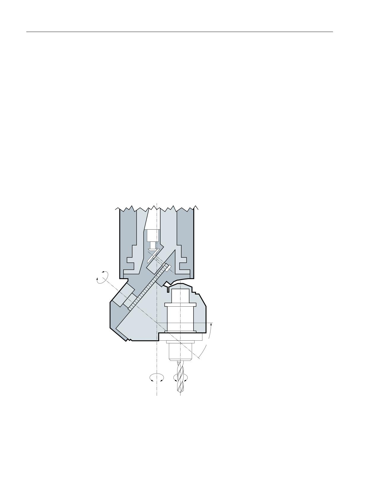
A machine tool with a universal milling head has got at least 5 axes:
•
3 linear axes
- for linear movement [X, Y, Z]
- move the machining point to any random position in the working area
•
2 rotary swivelling axes
- are arranged under a configurable angle (mostly 45 Degree)
- enable the tool to define orientations in space
(are limited to a hemisphere in a 45 degree arrangement)
$ಿ
˳
&
7RRO D[LV
Figure 6-33
Schematic diagram of a machine tool with universal milling head
Transformations
320
Function Manual, 10/2020, 6FC5397-5GP40-0BA1
Orientation transformations
6.11 Cardan milling head
6.11.2
Fundamentals of cardan milling head
Note
To understand the transformation for the cardan milling head, knowledge of the general 5-axis
transformation according to Chapter "3 to 5-axis transformation (Page 220)" is assumed. Please
note that where no specific statements relating to the cardan milling head are made in the
following section, the statements relating to general 5-axis transformation apply.
A cardan milling head cannot be defined by a kinematic chain.
Applications
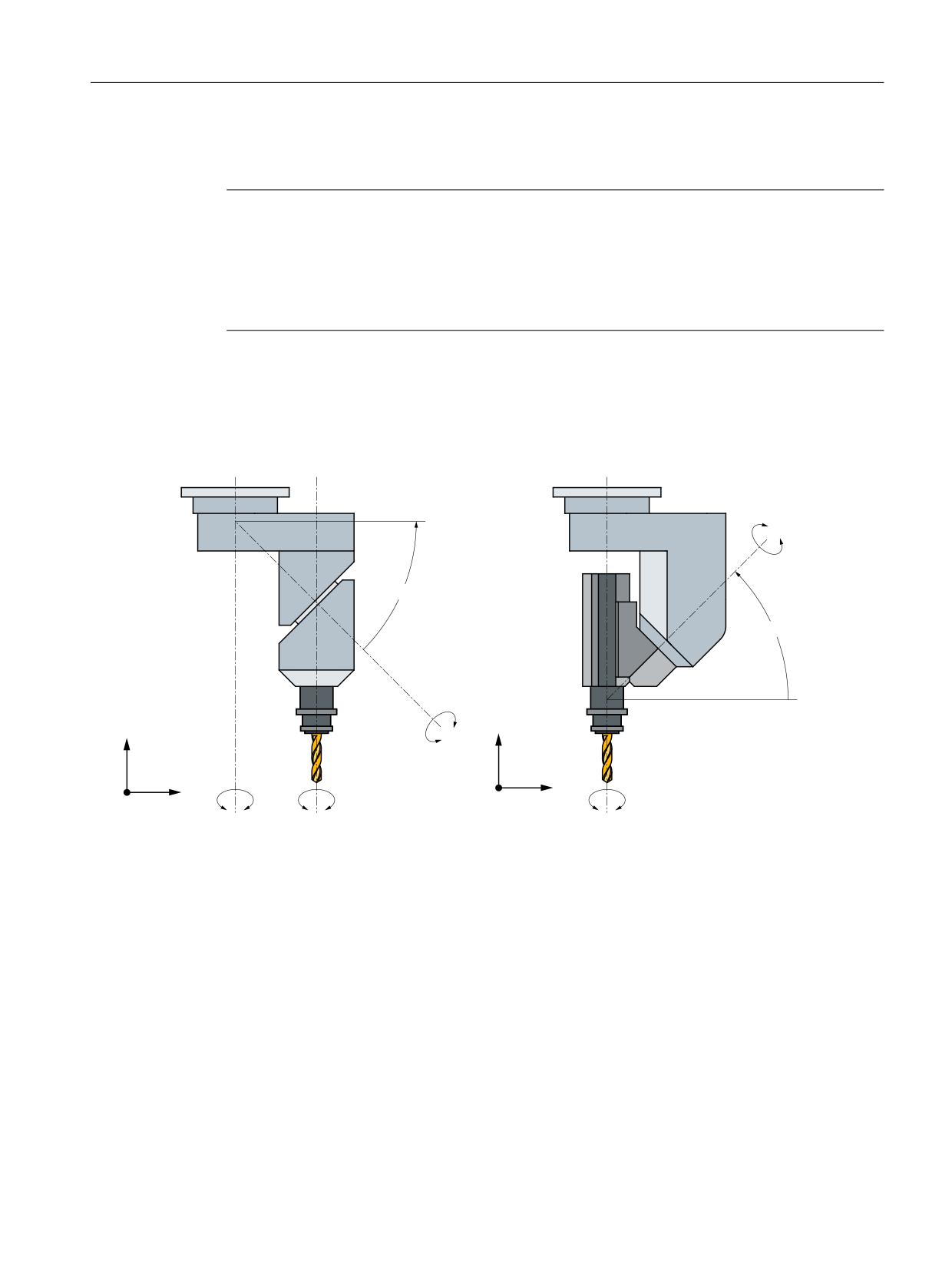
A cardan milling head is used for machining contours of sculptured parts at high feedrates. An
excellent degree of machining accuracy is achieved thanks to the rigidity of the head.
$ಿ
˳
˳
$ಿ
=
=
&
7RRO D[LV
&
7RRO D[LV
;
;
Figure 6-34
Schematic representation of the cardan milling head versions
Configuring the nutator angle φ
The angle of the inclined axis can be configured in a machine data:
$MC_TRAFO5_NUTATOR_AX_ANGLE_1: for the first orientation transformation
$MC_TRAFO5_NUTATOR_AX_ANGLE_2: for the second orientation transformation
The angle must lie within the range of 0 degrees to +89 degrees.
Transformations
Function Manual, 10/2020, 6FC5397-5GP40-0BA1
321
Orientation transformations
6.11 Cardan milling head
Tool orientation
Tool orientation at zero position can be specified as follows:
• parallel to the first rotary axis or
• perpendicular to it, and in the plane of the specified axis sequence
Types of kinematics
The axis sequence of the rotary axes and the orientation direction of the tool at zero position are
set for the different types of kinematics using the following machine data:
$MC_TRAFO_TYPE_1 ... $MC_TRAFO_TYPE_10
Axis designation scheme
As for the other 5-axis transformations, the following applies:
the rotary axis
...A is parallel to X: A' is below the angle φ to the X axis
...B is parallel to Y: B' is below angle φ to the Y axis
...C is parallel to Z: C' is below angle φ to the Z axis
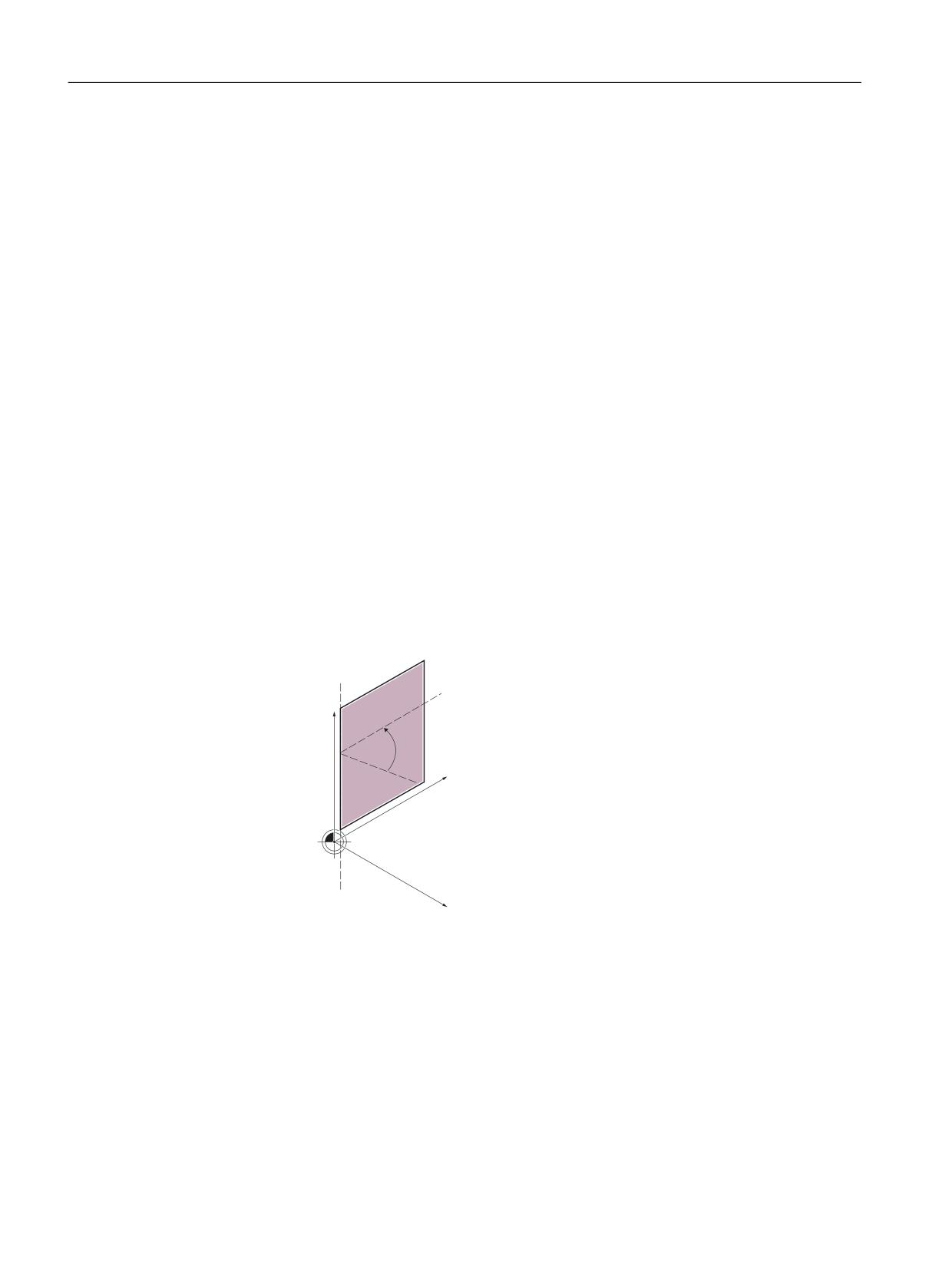
Angle definition
&
$
=
˳
<
$v
;
Figure 6-35
Position of axis A'
Axis A' is positioned in the plane spanned by the rectangular axes of the designated axis
sequence. If the axis sequence is CA', for example, the axis A' is positioned in the plane Z-X. The
angle φ is then the angle between the A' axis and the X axis.
Transformations
322
Function Manual, 10/2020, 6FC5397-5GP40-0BA1

Orientation transformations
6.11 Cardan milling head
6.11.3
Parameterization
Setting the type of transformation
The transformation type is set with the machine data of the corresponding transformation data
block:
MD24100, ... MD25190 $MC_TRAFO_TYP_n, with n = 1, 2, 3, ...
Bit
<value>
Description
7
1
Activation of the transformation for cardan milling head
6 - 5
Moving component
00
Movable tool
01
Movingworkpiece
10
movable tool and workpiece
4 - 3
Direction of orientation of tool in position zero
00
X direction
01
Y direction
10
Z direction
2 - 0
Axis sequence
000
AB' or A'B
001
AC' or A'C
010
BA' or B'A
011
BC' or B'C
100
CA' or C'A
101
CB' or C'B
The following transformation types can be set:
Axis se-
Moving component: Bits 6 - 5
quence:
Tool
Workpiece
Tool/workpiece
Bits 0 - 2
00
01
10
Zero position 1)
Zero position 1)
Zero position 1)
X
Y
Z
X
Y
Z
X
Y
Z
00
01
10
00
01
10
00
01
10
AB' / A'B
x
x
-
-
-
-
-
-
-
000
AC' / A'C
x
-
x
-
-
-
-
-
-
001
BA' / B'A
x
x
-
-
-
-
x
x
010
BC' / B'C
-
x
x
-
x
x
-
-
-
011
CA' / C'A
x
-
x
-
-
-
-
-
-
100
Transformations
Function Manual, 10/2020, 6FC5397-5GP40-0BA1
323

Orientation transformations
6.11 Cardan milling head
Axis se-
Moving component: Bits 6 - 5
quence:
Tool
Workpiece
Tool/workpiece
Bits 0 - 2
00
01
10
Zero position 1)
Zero position 1)
Zero position 1)
X
Y
Z
X
Y
Z
X
Y
Z
00
01
10
00
01
10
00
01
10
CB' / C'B
-
x
x
-
-
-
-
-
-
101
1) Orientation of the tool in the zero position: Bits 3 - 4
x: Transformation type can be set
-: Transformation type cannot be set
Active machining plane
The tool orientation at the zero position can be set not only in the Z direction. For this reason,
ensure that the active working plane is set so that the tool length compensation acts in the tool
orientation direction.
The active machining plane should always be the plane according to which the tool orientation
is set in position zero.
Other settings
The geometry information used by the cardan milling head transformation for calculation of the
axis values is set in the same way as that of the other 5-axis transformations.
6.11.4
Traverse of the cardan milling head in JOG mode
JOG
In JOG mode, the linear axes can be traversed normally. It is, however, difficult to set the
orientation correctly by traversing these axes.
Transformations
324
Function Manual, 10/2020, 6FC5397-5GP40-0BA1
Orientation transformations
6.12 Generic 5-axis transformation and variants
6.12
Generic 5-axis transformation and variants
6.12.1
Functionality
Scope of functions
The range of functions of generic 5-axis transformation covers the implemented 5-axis
transformations (see Section "3 to 5-axis transformation (Page 220)") for perpendicular rotary
axes as well as transformations for the cardan milling head (one rotary axis parallel to a linear
axis, the second rotary axis at any angle to it, see Section "Cardan milling head (Page 320)").
Note
The functionality of the generic 5-axis transformation can also be mapped via kinematic chains,
with the exception of cardan milling heads.
Field of application
In certain cases, it may not be possible to compensate the conventional transformation machine
accuracy, e.g. if:
• the rotary axes are not exactly mutually perpendicular or
• one of the two rotary axes is not positioned exactly parallel to the linear axes
In such cases, generic 5-axis transformation can produce better results.
Programming example
for generic 5-axis transformation is shown in Section "Example for Generic 5-axis
Transformation".
Activation
Generic 5-axis transformation can also be activated like any other orientation transformation
using the TRAORI() or TRAORI(n) command (where n is the number of the transformation).
Furthermore, the basic transformation can be transferred in the call in three other parameters,
e.g. TRAORI(1, 1.1, 1.5, 8.9).
A transformation can be deselected implicitly by selecting another transformation or explicitly
with TRAFOOF.
Transformations
Function Manual, 10/2020, 6FC5397-5GP40-0BA1
325

Orientation transformations
6.12 Generic 5-axis transformation and variants
6.12.2
Description of machine kinematics
Machine types
Like the existing 5-axis transformations, there are three different variants of generic 5-axis
transformation:
1. Machine type: Rotatable tool
Both rotary axes change the orientation of the workpiece. The orientation of the workpiece is
fixed.
2. Machine type: Rotatable workpiece
Both rotary axes change the orientation of the workpiece. The orientation of the tool is fixed.
3. Machine type: Rotatable tool and rotatable workpiece - one rotary axis changes the tool
orientation and the other the workpiece orientation.
Configurations
As previously, the machine configurations are defined in the following machine data (see
Section "Configuration of a machine for 5-axis transformation (Page 246)"):
$MC_TRAFO_TYPE_1, ..., _8
Additional types have been introduced for generic 5-axis transformation:
Table 6-1
Overview of machine types for the generic 5-axis transformation
Machine type
1
2
3
Swivel/rotatable:
tool
workpiece
Tool/workpiece
Transformation types
24
40
56
Rotary axis direction
The direction of the rotary axis is defined by the following machine data:
$MC_TRAFO5_AXIS1_n (1st rotary axis) and
$MC_TRAFO5_AXIS2_n (2nd rotary axis)
where n is 1 or 2 for the first or second 5-axis transformation in the system respectively. The
machine data specified above are fields with three values, which describe that axis direction
vectorially (similar to the description of rotary axes for orientable toolholder). The absolute value
of the vectors is insignificant; only the defined direction is relevant.
Example:
1. A-axis is the rotary axis (parallel to the x direction):
MD24570 $MC_TRAFO5_AXIS1_1[0] = 1.0 (direction first rotary axis)
MD24570 $MC_TRAFO5_AXIS1_1[1] = 0.0
MD24570 $MC_TRAFO5_AXIS1_1[2] = 0.0
2. B-axis is the rotary axis (parallel to the y direction):
Transformations
326
Function Manual, 10/2020, 6FC5397-5GP40-0BA1
Orientation transformations
6.12 Generic 5-axis transformation and variants
MD24572 $MC_TRAFO5_AXIS2_1[0] = 0.0 (direction 2nd rotary axis)
MD24572 $MC_TRAFO5_AXIS2_1[1] = 1.0
MD24572 $MC_TRAFO5_AXIS2_1[2] = 0,0
6.12.3
Generic orientation transformation variants
Extension
Generic orientation transformation for 5-axis transformation has been extended with the
following variants for 3-and 4-axis transformation:
Variant 1
4-axis transformations
A 4-axis transformation is characterized by the exclusive use of the first rotary axis as an entry
axis of the transformation. The following applies:
MD24110 $MC_TRAFO_AXES_IN_1[4] = 0 (axis assignment for transformation 1) or
MD24210 $MC_TRAFO_AXES_IN_2[4] = 0 (axis assignment for transformation 2)
Variant 2
3-axis transformations
In a 3-axis transformation, one of the geometry axes is not present, by entering a zero in the
field:
MD24120 $MC_TRAFO_GEOAX_ASSIGN_TAB_1[n] (assignment between geometry axis and
channel axis for transformation 1)
MD24220 $MC_TRAFO_GEOAX_ASSIGN_TAB_2[n] (assignment between geometry axis and
channel axis for transformation 2)
Transformation types
Both variants of generic 3- or 4-axis transformation are described by the following
transformation types:
•
3- or 4-axis transformation with rotatable tool
$MC_TRAFO_TYPE_n = 24
•
3- or 4-axis transformation with rotatable workpiece
$MC_TRAFO_TYPE_n = 40
In conventional 3-axis or 4-axis transformations, the transformation type also defined the basic
tool orientation in addition to the position of the rotary axis, which could then no longer be
influenced.
Transformations
Function Manual, 10/2020, 6FC5397-5GP40-0BA1
327
Orientation transformations
6.12 Generic 5-axis transformation and variants
Effects on orientations
Generic 3-axis or 4-axis transformation has the following effect on the various orientations:
The resulting tool orientation is defined according to the hierarchy specified for generic 5-axis
transformation.
Priority:
• high: programmed orientation,
• medium: tool orientation and
• low: basic orientation
Allowance is made, in particular, for the following orientations:
• A programmed tool orientation
• A basic tool orientation, modified by orientable toolholders.
Note
Further information on programmable tool orientation and on basic tool orientation can be
found in:
Further information
Function Manual Tools, tool offset, orientable tool carriers
Programming Manual, Fundamentals
Comparison
Besides the 3- and 4-axis transformations mentioned in Section "3- and 4-axis Transformations",
the following differences should be noted:
• Position of the rotary axis:
- can be arbitrary
- need not be parallel to a linear axis
• Direction of the rotary axis
- Must be defined by the following machine data:
MD24570 $MC_TRAFO5_AXIS1_1[n] (direction 1st rotary axis) or
MD24670 $MC_TRAFO5_AXIS1_2[n] (direction 1st rotary axis)
• Basic tool orientation
- Must be defined by the following machine data:
MD24574 $MC_TRAFO5_BASE_ORIENT_1[n] (workpiece orientation) or
MD24674 $MC_TRAFO5_BASE_ORIENT_2[n] (workpiece orientation)
• Selection of a generic 3-/4-axis transformation
- Optional tool orientation can be transferred as in the case of a generic 5-axis
transformation.
Transformations
328
Function Manual, 10/2020, 6FC5397-5GP40-0BA1

Orientation transformations
6.12 Generic 5-axis transformation and variants
6.12.4
Parameterization of orientable toolholder data
Application
Machine types for which the table or tool can be rotated, can either be operated as true 5-axis
machines or as conventional machines with orientable toolholders. In both cases, machine
kinematics is determined by the same data, which, due to different parameters, previously had
to be entered twice - for toolholder via system variables and for transformations via machine
data. The new transformation type 72 can be used to specify that these two machine types
access identical data.
Transformation type 72
The following machine data can be used to define a generic 5-axis transformation for
transformation type 72 with kinematic data read from the data for an orientable toolholder.
MD24100 $MC_TRAFO_TYPE_1 (definition of transformation 1 in the channel) or
MD24200 $MC_TRAFO_TYPE_2 (definition of transformation 2 in the channel)
From this number data is made available via machine data MD24582
$MC_TRAFO5_TCARR_NO_1 (TCARR-Number for the first 5-axis transformation) for the first or
MD24682 $MC_TRAFO5_TCARR_NO_2 (TCARR-Number for the second 5-axis transformation)
for the second orientation transformation. The corresponding transformation type can then be
derived from the content of kinematic type with parameter $TC_CARR23 - see following table.
Table 6-2
Machine types for generic 5-axis transformation
Machine type
1
2
3
4
Swivel/
tool
workpiece
Tool/workpiece
Type 3 or orienta-
rotatable:
ble toolholder
Kinematic type:
T
P
M
T, P, M
Transformation
24
40
56
72 from content of
type:
$TC_CARR23
Transformations
Function Manual, 10/2020, 6FC5397-5GP40-0BA1
329

Orientation transformations
6.12 Generic 5-axis transformation and variants
Note
The transformation only takes place if the orientable toolholder concerned is available and the
value of $TC_CARR23 contains a valid entry for type M, P or T kinematics in lower or upper case.
Transformation machine data for the first orientation transformation listed in the tables below
are equally valid for the second orientation transformation. All other machine data that may
affect the transformation characteristics and do not appear in the tables below, remain valid and
effective:
MD24110/MD24210 $MC_TRAFO_AXES_IN_1/2 (axis assignment for transformation) or
MD24574/MD24674 $MC_TRAFO5_BASE_ORIENT_1/2 (basic tool orientation)
If in the tables below a second additive parameter appears in brackets for the parameters of the
orientable toolholder (e.g. $TC_CARR24 (+ $TC_TCARR64)), the sum of both values will only be
effective if the fine offset specified in setting data is active when the data is transferred from the
orientable toolholder.
SD42974 $SC_TOCARR_FINE_CORRECTION = TRUE (fine offset TCARR on/off)
Activation
The most significant parameter values of an orientable toolholder for a transformation can be
activated in the part program with NEWCONF. Alternatively, the machine data concerned for
transformation type 72 can be activated via the HMI user interface.
Assignment for all types of transformation
The assignments between the toolholder data for writing the linear offsets and the
corresponding machine data for kinematic transformations are determined by the
transformation type. The following assignment of all other parameters is identical for all three
possible types of transformation:
Assignment for all types of transformation together identical
MD24100 $MC_TRAFO_TYPE_1 (definition of transfor-
24
$TC_CARR23 =
T
mation 1 in the channel)
40
P
56
M
MD24570 $MC_TRAFO5_AXIS1_1[0] (direction 1st rotary axis)
$TC_CARR7
MD24570 $MC_TRAFO5_AXIS1_1[1]
$TC_CARR8
MD24570 $MC_TRAFO5_AXIS1_1[2]
$TC_CARR9
MD24572 $MC_TRAFO5_AXIS2_1[0] (direction 2nd rotary axis)
$TC_CARR10
MD24572 $MC_TRAFO5_AXIS2_1[1]
$TC_CARR11
MD24572 $MC_TRAFO5_AXIS2_1[2]
$TC_CARR12
MD24510 $MC_TRAFO5_ROT_AX_OFFSET_1[0] (position offset of
$TC_CARR24 (+$TC_TCARR64)
rotary axes 1/2/3 for 5-axis transformation) 1)
MD24510 $MC_TRAFO5_ROT_AX_OFFSET_1[1]
$TC_CARR25 (+$TC_TCARR65)
Transformations
330
Function Manual, 10/2020, 6FC5397-5GP40-0BA1

Orientation transformations
6.12 Generic 5-axis transformation and variants
Assignment for all types of transformation together identical
MD24520 $MC_TRAFO5_ROT_SIGN_IS_PLUS_1[0] (sign of rotary ax-
TRUE*
is 1/2/3 for 5-axis transformation 1)
MD24520 $MC_TRAFO5_ROT_SIGN_IS_PLUS_1[1]
TRUE*
*) Machine data MD24520/MD24620 $MC_TRAFO5_ROT_SIGN_IS_PLUS_1/2 are redundant.
They are used to invert the direction of rotation of the assigned rotary axis. However, this can
also be achieved by inverting the direction of axis vector $MC_TRAFO5_AXIS1/2_1/2. It is for this
reason that there is no corresponding parameter for the orientable toolholder. For the purpose
of absolute clarity, the following machine data must be ignored:
MD24520/MD24620 TRAFO5_ROT_SIGN_IS_PLUS_1/2
Assignments for transformation type 24
Toolholder data assignments dependent on transformation type 24
Transformation type "T" (in accordance with MD24100 $MC_TRAFO_TYPE_1 = 24)
MD24500 $MC_TRAFO5_PART_OFFSET_1[0] (transla-
$TC_CARR1 (+$TC_TCARR41)
tion vector of 5-axis transformation 1)
MD24500 $MC_TRAFO5_PART_OFFSET_1[1]
$TC_CARR2 (+$TC_TCARR42)
MD24500 $MC_TRAFO5_PART_OFFSET_1[2]
$TC_CARR3 (+$TC_TCARR43)
MD24560 $MC_TRAFO5_JOINT_OFFSET_1[0] (vector
$TC_CARR4 (+$TC_TCARR44)
of the kinematic offset of 5-axis transformation 1)
MD24560 $MC_TRAFO5_JOINT_OFFSET_1[1]
$TC_CARR5 (+$TC_TCARR45)
MD24560 $MC_TRAFO5_JOINT_OFFSET_1[2]
$TC_CARR6 (+$TC_TCARR46)
MD24550 $MC_TRAFO5_BASE_TOOL_1[0] (vector of
$TC_CARR15 (+$TC_TCARR55)
basic tool when 5-axis transformation is active) 1)
MD24550 $MC_TRAFO5_BASE_TOOL_1[1]
$TC_CARR16 (+$TC_TCARR56)
MD24550 $MC TRAFO5_BASE_TOOL_1[2]
$TC_CARR17 (+$TC_TCARR57)
Assignments for transformation type 40
Toolholder data assignments dependent on transformation type 40
Transformation type "P" (in accordance with MD24100 $MC_TRAFO_TYPE_1 = 40)
MD24550 $MC_TRAFO5_BASE_TOOL_1[0]
$TC_CARR4 (+$TC_TCARR44)
MD24550 $MC_TRAFO5_BASE_TOOL_1[1]
$TC_CARR5 (+$TC_TCARR45)
MD24550 $MC_TRAFO5_BASE_TOOL_1[2]
$TC_CARR6 (+$TC_TCARR46)
MD24560 $MC_TRAFO5_JOINT_OFFSET_1[0]
$TC_CARR15 (+$TC_TCARR55)
MD24560 $MC_TRAFO5_JOINT_OFFSET_1[1]
$TC_CARR16 (+$TC_TCARR56)
MD24560 $MC_TRAFO5_JOINT_OFFSET_1[2]
$TC_CARR17 (+$TC_TCARR57)
MD24500 $MC_TRAFO5_PART_OFFSET_1[0]
$TC_CARR18 (+$TC_TCARR58)
Transformations
Function Manual, 10/2020, 6FC5397-5GP40-0BA1
331

Orientation transformations
6.12 Generic 5-axis transformation and variants
Transformation type "P" (in accordance with MD24100 $MC_TRAFO_TYPE_1 = 40)
MD24500 $MC_TRAFO5_PART_OFFSET_1[1]
$TC_CARR19 (+$TC_TCARR59)
MD24500 $MC_TRAFO5_PART_OFFSET_1[2]
$TC_CARR20 (+$TC_TCARR60)
Assignments for transformation type 56
Toolholder data assignments dependent on transformation type 56
Transformation type "M" (in accordance with MD24100 $MC_TRAFO_TYPE_1 = 56)
MD24560 $MC_TRAFO5_JOINT_OFFSET_1[0] (vector of
$TC_CARR1 (+$TC_TCARR41)
the kinematic offset of 5-axis transformation 1)
MD24560 $MC_TRAFO5_JOINT_OFFSET_1[1]
$TC_CARR2 (+$TC_TCARR42)
MD24560: TRAFO5_JOINT_OFFSET_1[2]
$TC_CARR3 (+$TC_TCARR43)
MD24550 $MC_TRAFO5_BASE_TOOL_1[0]
$TC_CARR4 (+$TC_TCARR44)
MD24550 $MC_TRAFO5_BASE_TOOL_1[1]
$TC_CARR5 (+$TC_TCARR45)
MD24550 $MC_TRAFO5_BASE_TOOL_1[2]
$TC_CARR6 (+$TC_TCARR46)
MD24558 $MC_TRAFO5_JOINT_OFFSET_PART_1[0]
$TC_CARR15 (+$TC_TCARR55)
MD24558 $MC_TRAFO5_JOINT_OFFSET_PART_1[1]
$TC_CARR16 (+$TC_TCARR56)
MD24558 $MC_TRAFO5_JOINT_OFFSET_PART_1[2]
$TC_CARR17 (+$TC_TCARR57)
MD24500 $MC_TRAFO5_PART_OFFSET_1[0]
$TC_CARR18 (+$TC_TCARR58)
MD24500 $MC_TRAFO5_PART_OFFSET_1[1]
$TC_CARR19 (+$TC_TCARR59)
MD24500 $MC_TRAFO5_PART_OFFSET_1[2]
$TC_CARR20 (+$TC_TCARR60)
Example of parameterization
The first 5-axis transformation is to obtain its data from machine data and the second, in
contrast, is to be parameterized using the data from the 3rd orientable toolholder.
MD24100 $MC_TRAFO_TYPE_1 = 24
; first 5-axis transformation
MD24200 $MC_TRAFO_TYPE_2 = 72
; second 5-axis transformation
MD24682 $MC_TRAFO5_TCARR_NO_2 = 3;
; parameterize data of the third orientable
; toolholder
6.12.5
Extension of the generic transformation to 6 axes
6-axis transformation is an extension of the generic 5-axis transformation to include an
additional rotary axis. This allows rotation of the tool around itself to be defined.
In addition to the machine data for 5-axis transformation, to parameterize 6-axis
transformation, additional settings must be made in the subsequently listed machine data.
Transformations
332
Function Manual, 10/2020, 6FC5397-5GP40-0BA1

Orientation transformations
6.12 Generic 5-axis transformation and variants
Parameter assignment: Transformation type
The transformation type is set on a channel-for-channel basis using:
$MC_TRAFO_TYPE_<x> = <transformation type>
The transformation type to be set is obtained from the machine type and/or the allocation of the
three rotary axes regarding tool and workpiece orientation:
<Transformation type>
24 1)
40 1)
56 2)
57 3)
Machine type
1
2
3
4
Tool orientation
3 rotary axes
---
2 rotary axes
1 rotary axis
Workpieceorientation
---
3 rotary axes
1 rotary axis
2 rotary axes
1)
The first rotary axis of the transformation is the rotary axis that in the kinematic chain is located next
for the workpiece.
The third rotary axis of the transformation is the rotary axis that in the kinematic chain is located next
for the tool.
When the second rotary axis traverses, then the third rotary axis is also moved.
2)
The second rotary axis of the transformation is the rotary axis that in the kinematic chain is located next
for the workpiece.
The third rotary axis of the transformation is the rotary axis that in the kinematic chain is located next
for the tool.
When the first rotary axis traverses, then the third rotary axis is also moved.
3)
The first rotary axis of the transformation is the rotary axis that in the kinematic chain is located next
for the tool.
The third rotary axis of the transformation is the rotary axis that in the kinematic chain is located next
for the workpiece.
When the second rotary axis traverses, then the third rotary axis is also moved.
Note
Using transformation types 24, 40, 56 and 57, only those kinematics are formed, where the
three linear axes of the transformation form a right-handed Cartesian coordinate system - and,
there is no rotary axis between the linear axes in the kinematic chain.
Parameter assignment: Offset vectors for transformation type 57
For transformation type 57, the same as for rotary axes, the offset vectors are to be specified
starting from the tool to the workpiece zero:
Offset
Machine data
Tool tip → rotary axis 1
$MC_TRAFO5_BASE_TOOL_<x>[ 0 ... 2 ]
Rotary axis 1 → rotary axis 2
$MC_TRAFO5_JOINT_OFFSET_<x>[ 0 ... 2 ]
Rotary axis 2 → rotary axis 3
$MC_TRAFO6_JOINT_OFFSET_2_3_<x>[ 0 ... 2 ]
Rotary axis 3 → workpiece zero
$MC_TRAFO5_PART_OFFSET_<x>[ 0 ... 2 ]
Parameter assignment: Channel axis number of the 3rd rotary axis
The channel axis number of the third rotary axis is set in:
$MC_TRAFO_AXES_IN_<x>[ 5 ] = <channel axis number of the third rotary axis>
Transformations
Function Manual, 10/2020, 6FC5397-5GP40-0BA1
333
Orientation transformations
6.12 Generic 5-axis transformation and variants
Parameter assignment: Direction vector of the 3rd rotary axis
The direction vector of the third rotary axis is set in:
$MC_TRAFO5_AXIS3_<x>[ 0 ... 2 ] = <direction vector component>
Parameter assignment: Tool normal vector
It is not permissible that the tool normal vector is in parallel or is antiparallel to the basic tool
orientation vector (MD24574 $MC_TRAFO5_BASE_ORIENT_<x>). It is set in:
$MC_TRAFO6_BASE_ORIENT_NORMAL_<x>[ 0 ... 2 ] = <component of the tool normal vector>
Parameter assignment: Offset vector between the second and third rotary axes
The offset vector between the second and third rotary axes is set in:
$MC_TRAFO6_JOINT_OFFSET_2_3_<x>[ 0 ... 2 ] = <component of the offset vector>
Orientation
With the extension of the generic orientation transformation to six axes, all three degrees of
freedom of the orientation can be freely selected. They can be uniquely defined through the
position of a rectangular Cartesian coordinate system. The axis direction of the third axis
defines the orientation.
Two degrees of freedom are required to specify this axis direction. The third degree of freedom is
defined via a rotation around this axis direction, e.g. by specifying an angle THETA or a direction
vector for one of the two other axes of the coordinate system (see Chapter "Rotations of
orientation vector (Page 307)").
Addresses AN3, BN3, CN3 define the direction of the second axis of the coordinate system, i.e.
the orientation normal vector. The orientation normal vector, programmed with addresses
AN3, BN3, CN3, should be perpendicular to the orientation. If this is not the case, then the
programmed orientation normal vector is internally modified to achieve this. Then, the
modified orientation normal vector lies in the plane formed by the programmed orientation and
orientation normal vector - and is perpendicular to the orientation vector. This
orthogonalization is only possible if the two programmed vectors are neither parallel nor
antiparallel. Alarm 4342 is output if this condition is not satisfied.
Direction vectors in the tool data
Orientation vector
Vector components (x,y,z) of the orientation vector of a tool can be defined in the tool data using
$TC_DPV or $TC_DPV3 - $TC_DPV5.
Further information: Function Manual Tools; Tool offsets, sum and setup offsets
Transformations
334
Function Manual, 10/2020, 6FC5397-5GP40-0BA1

Orientation transformations
6.12 Generic 5-axis transformation and variants
Orientation normal vector
Vector components (x,y,z) of the orientation normal vector of a tool can be defined in the tool
data using $TC_DPVN3 - $TC_DPVN5. The significance of the vector components is analogous to
the vector components of the orientation vector:
• $TC_DPVN3: Component in the direction of the tool length L1,
• $TC_DPVN4: Component in the direction of the tool length L2
• $TC_DPVN5: Component in the direction of the tool length L3.
The following settings must be made so that the tool data for the orientation normal vector can
be used:
MD18114 $MN_MM_ENABLE_TOOL_ORIENT = 3 (assign tool cutting edges orientation)
The coordinate system is not rotated by rotating the tool with AN3, BN3, CN3 or THETA.
Default setting of the orientation normal vector
The initial state of the orientation normal vector is defined when activating the transformation
in one of the following ways:
1. For a TRAORI function call, vector components (x,y,z) are transferred as parameters 8 - 10:
TRAORI(p1, p2, p3, p4, p5, p6, p7, p8, p9, p10)
2. If, when calling the TRAORI function, no orientation normal vector is specified, and one tool
is active, then vector components (x,y,z) are taken from the tool data:
$TC_DPVN3, $TC_DPVN4, $TC_DPVN5
3. If, when calling the TRAORI function, no orientation normal vector is specified, and no tool
is active, then vector components (x,y,z) are taken from the following machine data:
MD24567 $MC_TRAFO6_BASE_ORIENT_NORMAL_<x>[ 0 ... 2 ] (tool normal vector)
The position of the orientation coordinate system of a standard tool depends on the active
plane (G17, G18, G19) corresponding to the following table:
G17
G18
G19
Direction of the orientation vector
Z
Y
X
Direction of the orientation normal vector
Y
X
Z
See also
Example of a generic 6-axis transformation (Page 367)
6.12.6
Extension of the generic transformation to 7 axes
Application
The generic 5-/6-axis transformation with transformation type 24 is extended by a 7th or
6th axis, which rotates the workpiece. The work space of the transformation can be expanded
in this way.
Transformations
Function Manual, 10/2020, 6FC5397-5GP40-0BA1
335
Orientation transformations
6.12 Generic 5-axis transformation and variants
Requirement
For generic 7-axis transformation there must be at least 6 or 7 axes.
Function
Another 7th axis is required in connection with the generic 6-axis transformation which rotates
the workpiece. This 7th Axis is considered only along with transformation type 24 (generic 6-
axis transformation having 3 rotary axes that move the tool ).
The position of the 7th axis is specified according to a strategy of the CAD system and settled
with the Cartesian position (X, Y, Z) by the generic transformation in such a way that the axes
always approach the TCP position programmed with reference to the workpiece, independently
of the position of the 7th axis. If ORIWKS is active, the end orientation programmed with
reference to the workpiece is also rotated by the 7th axis. This way it is possible to program the
orientation in relation to the workpiece.
The transformation uses the 7th axis as the observed input variable.
To configure the 7th axis, the channel machine data of the 5-/6-axis transformation is extended
by one field containing the 3 components of the direction vector of the 7th axis and an axis
offset.
This gives the following advantages:
• The contour and the orientation at the workpiece can be programmed in relation to the
workpiece.
• The programmed feed is maintained in the contour, even if the 7th axis also moves.
• All the contour-related control functions can be used.
• The displayed WCS position corresponds to the programmed position.
• The transformation is configured as in generic 6-axis transformation. One can switch
between a 6-axis and a 7-axis transformation smoothly.
• In case of large radius circular interpolation, the release of singularities incorporating the 7th
axis.
Notations
Dedicated machine data exist for each general transformation and for each orientation
transformation that are differentiated by the suffixes _1, _2 etc. (e.g. $MC_TRAFO_TYPE_1,
$MC_TRAFO_TYPE_2 etc.). In the following, only the names for the first transformation are
specified, i.e. those with the suffix _1. If a transformation other than the first is parameterized,
the correspondingly modified names must be used.
Transformations
336
Function Manual, 10/2020, 6FC5397-5GP40-0BA1

Orientation transformations
6.12 Generic 5-axis transformation and variants
Description of the kinematics
The 7-axis transformation builds on the generic 5-/6-axis transformation.
Note
The 7-axis transformation also covers kinematics in which the 6th axis is not available. In the
following, we speak exclusively about a 7th axis or about a 7-axis transformation, even when it
is actually the 6th axis in connection with a 5-axis kinematics.
The 7-axis transformation types only cover those kinematics in which the three linear axes form
a rectangular Cartesian coordinate system, i.e. no kinematics are covered in which at least one
rotary axis lies between two linear axes in the kinematic chain.
There is only one machine kinematics for which a 7th axis can be configured. It is designated by
the Transformation Type 24:
$MC_TRAFO_TYPE_1 = 24 Rotary tool: Three (or two) axes rotate the tool; the 7th axis rotates
the workpiece.
The extensions of the following machine data are required to configure a generic 7-axis
transformation:
Machine data
extension
$MC_TRAFO_AXES_IN_1[9]
The channel axis index of the 4th rotary axis is recor-
ded here.
$MC_TRAFO_AXES_IN_1[10] and $MC_TRA-
This machine data is to be assigned with default value
FO_AXES_IN_1[11]
of 0. (default setting)
$MC_TRAFO_AXES_IN_1[6..8]
This machine data is not evaluated by the generic 7-
axis transformation.
$MC_TRAFO7_EXT_AXIS1_1[0..2]
The direction of the 4th rotary axis is specified here.
$MC_TRAFO7_EXT_AX_OFFSET_1[0..2]
A position offset of the 4th rotary axis is entered here.
Transformations
Function Manual, 10/2020, 6FC5397-5GP40-0BA1
337
Orientation transformations
6.12 Generic 5-axis transformation and variants
MR
$
MR
&
&
PR
WR
W
;
SR
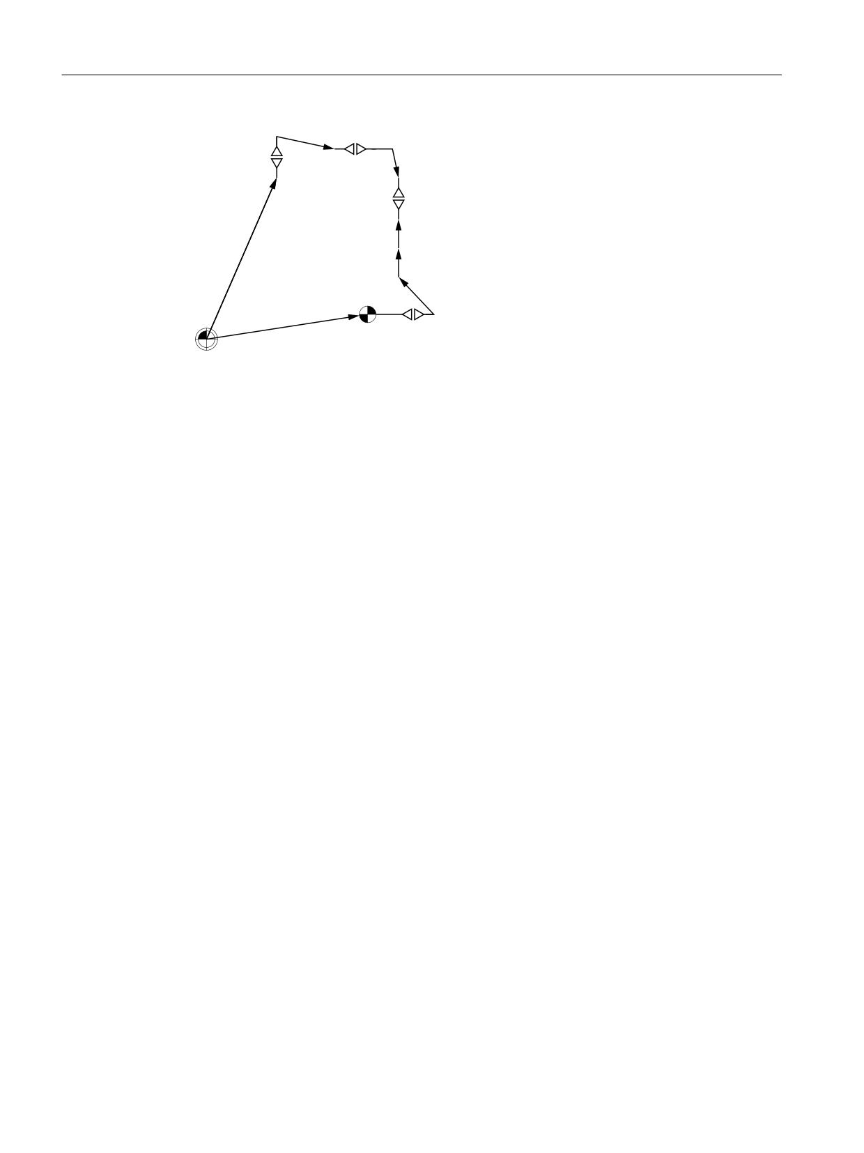
=HUR SRLQW WRRO
(
WDEOH
0DFKLQH ]HUR
mo:
Position vector in MCS
po:
$MC_TRAFO5_PART_OFFSET_n[0..2]
x.
Vector of programmed position in the WCS
t:
Tool correction vector
to:
$MC_TRAFO5_BASE_TOOL_n[0..2]
jo:
$MC_TRAFO5_JOINT_OFFSET_n[0..2]
jo23:
$MC_TRAFO6_JOINT_OFFSET_2_3_n[0..2]
Figure 6-36
Schematic diagram of 7-axis kinematics
Programming
1. Programming the Cartesian position
The position of the 7th axis must be programmed in the workpiece coordination system in
addition to the Cartesian position. The Cartesian position is thus programmed in relation to
the constant workpiece. The 7-axis transformation converts the WCS position via the rotation
of the 7th axis in the basic coordinate system. Possibly programmed or set frames are
normally settled before the 7-axis transformation.
2. Programming of orientation
All programming options of the generic 5/6-axis transformation are available while
programming the orientation. The 7th axis must always be programmed additionally.
Two different response types can be set in this context via the G command.
- The position of the 7th axis does not influence the programmed orientation.
- The programmed end orientation is rotated with the 7th axis.
Transformations
338
Function Manual, 10/2020, 6FC5397-5GP40-0BA1
Orientation transformations
6.12 Generic 5-axis transformation and variants
Orientation
1. Orientation with axis interpolation
If the 7th axis should have no influence on the programmed orientation, the G commands of
groups 25 and 51 must be set accordingly:
G group 25: ORIMKS
G group 51: ORIAXES (if MD21104 $MC_ORI_IPO_WITH_G_CODE = 1 is set).
The programmed positions of the rotary axes are not changed by the position of the 7th axis
in this case, but are approached directly. The orientation is programmed in relation to the
machine.
Example
Program code
TRAORI(1)
ORIAXES
ORIMKS
G1 X500 Y300 Z800 C15 A5 C1=10 E1=120
1. Orientation and large circle interpolation
If traversing is to be done with large radius circular interpolation, the end orientation is
rotated with the 7th axis.
G command group 25: ORIWKS
G command group 51: ORIVECT (if MD21104 $MC_ORI_IPO_WITH_G_CODE = 1 is set).
In this case the orientation must be programmed in relation to the workpiece. The
programmed orientation is thus related to the fixed workpiece. The position of the 7th axis
is thus not contained in the programmed orientation.
Example
Program code
TRAORI(1)
ORIVECT
ORIWKS
G1 X500 Y800 Z100 A3=0 B3=1 C3=0 AN3=0 BN3=0 CN3=-1 E1=-90
Frames
The basic coordinate system sits on the 7th axis. It is also rotated when the 7th axis rotates. This
way the workpiece coordinate system (WCS) does not remain stationary when the workpiece is
rotated over the 7th axis. A workpiece position rotated to the zero position of the 7th axis can
be compensated by an axial frame offset of the 7th axis.
Traversing with the 7th axis in JOG mode
Only the compensatory movements for the linear axes are created if the 7th axis is traversed in
the JOG mode with active 7-axis transformation. The position at the workpiece is kept constant
in this way. As the rotary axes go into the transformation only as input axes, they are not
influenced by the 7th axis during the JOG travel. The orientation at the workpiece is thus kept
variable.
Transformations
Function Manual, 10/2020, 6FC5397-5GP40-0BA1
339

Orientation transformations
6.12 Generic 5-axis transformation and variants
6.12.7
Cartesian manual travel with generic transformation
Note
Option
The "Handling transformation package" option is necessary for the function.
Functionality
With function "Cartesian manual travel", the following Cartesian coordinate system can be set
for traversing geometry and orientation axis in the JOG mode:
• Basic coordinate system (BCS)
• Workpiece coordinate system (WCS)
• Tool coordinate system (TCS)
Traversing motion of linear and rotary axes is realized via the NC/PLC interface signals of the
geometry and/or orientation axes.
Note
For further information about the representation of the translations for the Cartesian manual
travel in the corresponding coordinate systems, see:
Further information
Kinematic transformations (Page 55)
Parameter assignment: Machine data
Coordinate systems
The following machine data not only activates the function, but also sets the permitted
coordinate systems, which can be toggled between:
MD21106 $MC_CART_JOG_SYSTEM, bit n = <value>
Bit n
Value
Meaning
0
1
Function active: Basic coordinate system (BCS)
1
1
Function active: Workpiece coordinate system (WCS)
2
1
Function active: Tool coordinate system (TCS)
Parameter assignment: Setting data
Defining the virtual kinematics for the orientation axes
The active virtual kinematics for manually traversing the orientation axes is defined using the
following setting data. Here, only kinematics can be set, where the rotary axes are perpendicular
to one another.
Transformations
340
Function Manual, 10/2020, 6FC5397-5GP40-0BA1

Orientation transformations
6.13 Programming
SD42660 $SC_ORI_JOG_MODE = <value>
Value
Meaning
0
The virtual kinematics are defined using transformation.
1
Rotation with Euler angles: Rotation sequence, ZX'Z'' convention
2
Rotation with Euler angles: XY'Z'' convention (RPY angle)
3
Rotation with Euler angles: Rotation sequence ZY'X'' convention (RPY angles)
4
Defining the rotation sequence using: MD21120 $MC_ORIAX_TURN_TAB_1
5
Defining the rotation sequence using: MD21130 $MC_ORIAX_TURN_TAB_2
Further explanations regarding orientation motion (see Chapters "Orientation (Page 262)" and
"Orientation axes (Page 292)").
Note
For further information on programming the rotations, see:
Further information
"NC Programming" Programming Manual
6.13
Programming
6.13.1
Activating TRAORI_DYN and TRAORI_STAT with TRAFOON
The orientation transformations (TRAORI_DYN and TRAORI_STAT) are activated in the part
program or synchronized action using the TRAFOON or TRAORI instructions. To be able to
activate a transformation parameterized with a kinematic chain with TRAORI_DYN or
TRAORI_STAT, this must be parameterized in the system variable $NT_TRAFO_INDEX (Page 28).
Additional information is provided at:
TRAFOON (Page 52)
TRAORI (Page 349)
Interface signals
The corresponding interface signals are described under Programming of the 3- to 5-axis
transformation (Page 351).
6.13.2
Modifying the orientation transformation after the machine measurement
(CORRTRAFO)
For machines with orientation transformations that were defined by means of kinematic chains,
the user can use the predefined CORRTRAFO function in order to modify the offset vectors or the
direction vectors of the orientation axes in the kinematic model of the machine after a machine
measurement.
Transformations
Function Manual, 10/2020, 6FC5397-5GP40-0BA1
341
Orientation transformations
6.13 Programming
Note
The correction values written with the CORRTRAFO function are not immediately effective in the
transformation. The correction values do not become effective until after a transformation
deselection, NEWCONF and transformation selection.
Syntax
<Corr_Status> = CORRTRAFO(<Corr_Vect>, <Corr_Index>, <Corr_Mode>,
[ <No_Alarm>])
Transformations
342
Function Manual, 10/2020, 6FC5397-5GP40-0BA1
Orientation transformations
6.13 Programming
Meaning
CORRTRAFO:
Function call
Transformations
Function Manual, 10/2020, 6FC5397-5GP40-0BA1
343

Orientation transformations
6.13 Programming
<Corr_Status>:
Function return value
Data type:
INT
Values:
0
The function was executed without an error.
1
No transformation is active.
2
The currently active transformation is not an orientation trans-
formation.
3
The active orientation transformation was not defined with kin-
ematic chains.
10
The <Corr_Index> call parameter is negative.
11
The <Corr_Mode> call parameter is negative.
12
Invalid reference to a section of a subchain (units position
of <Corr_Index>). The value must not be greater than the
number of orientation axes in the subchain.
13
Invalid reference to the orientation axis of a subchain (units
position of <Corr_Index>). The value must be less than the
number of orientation axes in the subchain.
14
Invalid reference to a subchain (tens position
of <Corr_Index>). Only the values 0 and 1 are permissible
(reference to part or tool chain). This error number occurs if the
subchain to which <Corr_Index> refers does not exist.
15
There is no correction element in the section referred to with
the <Corr_Index> parameter ($NT_CORR_ELEM_P or
$NT_CORR_ELEM_T).
20
Invalid correction mode (units position of <Corr_Mode>). On-
ly the values 0 and 1 are permissible.
21
Invalid correction mode (tens and/or hundreds position
of <Corr_Mode>). Only the units position can be not equal to
zero when writing an axis direction.
30
The hundreds position of <Corr_Mode> is invalid. Only the
values 0 and 1 are permissible.
31
The thousands position of <Corr_Mode> is invalid. Only the
values 0 and 1 are permissible.
40
The direction vector that is to be taken as axis direction is the
zero vector. This error can only happen if the thousands position
of <Corr_Mode> is equal to 0. If the thousands position of this
parameter is equal to 1 (monitoring of the maximum correction
deactivated), the zero vector can also be written.
41
For the correction of an offset vector, the difference to the cur-
rent value in at least one coordinate is greater than the maxi-
mum value specified by the setting data SD41610
$SN_CORR_TRAFO_LIN_MAX. The <Corr_Vect> parameter
will be overwritten by an error vector. This also applies when the
processing is aborted with alarm (see <No_Alarm> parame-
ter).
In the components whose correction value has exceeded the
permissible limit, the error vector has the difference, with the
correct sign, between the determined correction value and the
limit.
The content of the components that have not exceeded their
limit is zero.
Transformations
344
Function Manual, 10/2020, 6FC5397-5GP40-0BA1

Orientation transformations
6.13 Programming
42
For the correction of a direction vector, the angular displace-
ment compared to the current direction is greater than the
maximum value specified by the setting data SD41611
$SN_CORR_TRAFO_DIR_MAX.
43
The attempt to write a system variable was rejected because of
missing write rights.
<Corr_Vect>:
Correction vector
The content of the correction vector is defined by the following parameters
<Corr_Index> and <Corr_Mode>.
If <Corr_Status> = 41, the content of the vector is overwritten (see above).
Data type:
REAL
<Corr_Index>:
Section whose correction element is to be modified /
index of the orientation axis whose direction vector is to be modified
Data type:
INT
The <Corr_Index> parameter is decimal coded (units to tens position):
Units
Contains the index of the section or the orientation axis in the sub-
position:
chain.
Tens
Refers to the subchain.
position:
0x
Workpiece chain
1x
Tool chain
Transformations
Function Manual, 10/2020, 6FC5397-5GP40-0BA1
345
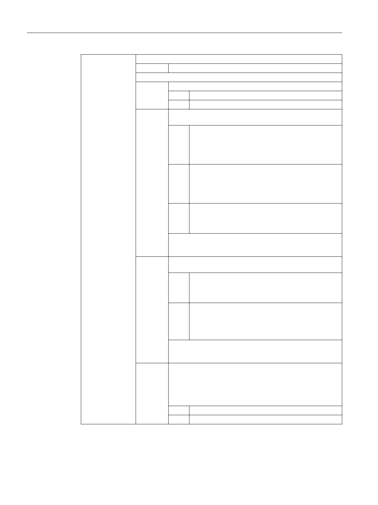
Orientation transformations
6.13 Programming
<Corr_Mode>:
Correction mode
Data type:
INT
The <Corr_Index> parameter is decimal coded (units to thousands position):
Units
Specifies which element is to be corrected.
position:
xxx0
Correction of a linear offset vector
xxx1
Correction of the direction vector of an orientation axis
Tens
Specifies how the correction element to which the content
position:
of <Corr_Index> refers, is to be modified.
xx0x
The correction vector is written immediately to the correc-
tion element.
This variant can be used to immediately write the correction
element without the index <n> of the relevant system data
($NK_OFF_DIR[<n>, ...]) having to be known.
xx1x
As 0, but with the difference that the transferred correction
value is interpreted in world coordinates.
A difference between variants 0 and 1 can always occur
when the kinematic chain in the initial state (positions of all
orientation axes equal to 0) contains other rotations.
xx2x
As 1, but with the difference that the correction value refers
to the entire section, i.e. a value is entered in the correction
element so that the entire section reaches the length de-
fined by the correction value.
Note:
The values 1 and 2 are not permissible when writing the direction
vector of an orientation axis.
Hundreds
Specifies how the content of the <Corr_Vect> parameter is to be
position:
interpreted.
x0xx
The transferred correction vector <Corr_Vect> contains
the entire new length of the correction element or the sec-
tion to which the <Corr_Index> in conjunction with the
tens position of <Corr_Mode> refers (absolute correction).
x1xx
The transferred correction vector <Corr_Vect> only con-
tains the difference compared to the current length of the
correction element or the section to which
the <Corr_Index> in conjunction with the tens position
of <Corr_Mode> refers (incremental correction).
Note:
For the correction of the direction vector of an orientation axis, the
content of the hundreds position must be 0.
Thousands
Specifies whether the correction is to be limited by the following
position:
maximum value:
• SD41610 $SN_CORR_TRAFO_LIN_MAX (Page 24)
or
• SD41611 $SN_CORR_TRAFO_DIR_MAX (Page 24)
0xxx
Monitoring of the maximum correction is active.
1xxx
Monitoring of the maximum correction is not active.
Transformations
346
Function Manual, 10/2020, 6FC5397-5GP40-0BA1

Orientation transformations
6.13 Programming
<No_Alarm>:
Behavior in the event of an error (return value > 0) (optional)
Data type:
BOOL
Value:
FALSE
In the event of an error, the program processing is stop-
(default)
ped and alarm 14103 is displayed.
TRUE
In the event of an error, the program processing is not
stopped and no alarm is displayed.
Application: User-specific reaction corresponding to the
return value
Note
In the event of an error when the function is called, either an alarm is output or an error number
returned (see <No_Alarm> parameter), so that the user can respond in a suitable way to the error
state. The cause of the error is described in more detail through an alarm parameter. An error
number returned instead of an alarm is identical to the alarm parameter.
See also
Angular deviation for rotation vectors for CORRTRAFO (Page 24)
Further information on CORRTRAFO
The kinematic structure of a machine with orientation transformation is described by one or two
kinematic chains (subchains), starting from the zero point of the world coordinate system. One
of the two chains, the tool chain, ends at the reference point of the tool, the other chain,
the workpiece chain ends in the zero point of the basic coordinate system.
The CORRTRAFO function writes lever arm lengths and axis directions on machines with an
orientation transformation in special correction elements. A kinematic chain is described, for
example, with elements of the type OFFSET, which are defined via $ NK_TYPE.
CORRTRAFO works with sections
The two subchains can each be divided into a maximum of four sections:
• Section 1 begins at the starting point of the chain and ends at the first orientation axis.
• Section 2 is the section between orientation axis 1 and orientation axis 2.
• Section 3 is the section between orientation axis 2 and orientation axis 3.
• Section 4 is the section between orientation axis 3 and the end of the tool or workpiece chain.
Each section may contain constant chain elements of the type OFFSET or ROT_CONST.
The following figure shows an orientation transformation with 2 orientation axes.
Transformations
Function Manual, 10/2020, 6FC5397-5GP40-0BA1
347
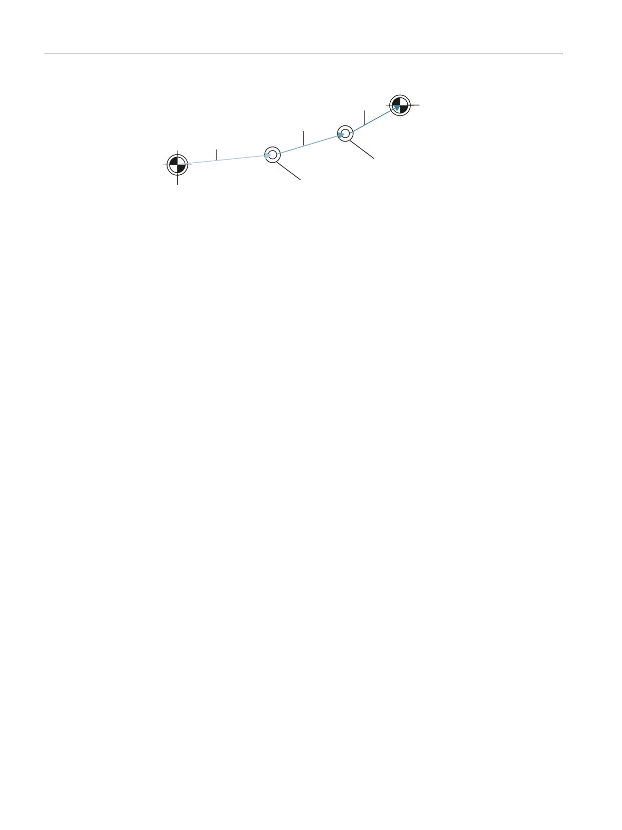
Orientation transformations
6.13 Programming
,
6HFWLRQ
:RUNSLHFH UHIHUHQFH SRLQW
ZRUNSLHFH FKDLQ (QG SRLQW
RI NLQHPDWLF FKDLQ
,
6HFWLRQ
,
6HFWLRQ
Y
˞
Y
˞
=HUR SRLQW RI WKH ZRUOG
FRRUGLQDWH V\VWHP
Figure 6-37
CORRTRAFO example
The sections are clearly defined: If you run through the kinematic subchain from the starting
point to the end point, the first section has the index 0, the next the index 1, and so on. The index
of the last section is then always equal to the number of orientation axes.
Correction elements
A reference can be made to a constant kinematic chain element (chain element of the type
$NK_TYPE[<n>] = "OFFSET") in each section with the $NT_CORR_ELEM_T[<n>, 0 ... 3] or
$NT_CORR_ELEM_P[<n>, 0 ... 3] system variables. The correction values that were determined
during the machine measurement are written to these elements with the CORRTRAFO function.
Example with transformation index = 1:
• $NT_CORR_ELEM_T[1,0] = "C_AXIS_OFFSET"; Offset of the C axis (orientation axis 1) in
section 1 is defined as correction element.
• $NT_CORR_ELEM_T[1,1] = "B_AXIS_OFFSET"; Offset of the B axis (orientation axis 2) in
section 2 is defined as correction element.
• $NT_CORR_ELEM_T[1,2] = "BASE_TOOL_OFFSET"; Offset of the B axis from the tool reference
point in section 3 is defined as correction element.
The sequence of the references in $NT_CORR_ELEM_T/P[<n>, 0 ... 3] must correspond to the
sections described above, i.e. only one chain element can be in $NT_CORR_ELEM_T/P [<n>, 0]
which is before the first orientation axis, etc.
The CORRTRAFO function writes the values determined by measuring the machine into the
correction elements defined in this way. The modification of the correction values is defined in
CORRTRAFO via the <Corr_Mode> parameter.
Closing a chain
If bit 7 or bit 8 are set in the $NT_CNTRL[<n>] system variable, additional constant chain
elements that establish a connection from the end point of the chain to the machine zero point
are automatically inserted internally at the end of the workpiece chain (bit 7) or before the
starting point of the tool chain (bit 8) ("close chain").
These automatically inserted elements cannot be written externally, only read (see the
$AC_TRAFO_CORR_ELEM_P/T system variables).
Transformations
348
Function Manual, 10/2020, 6FC5397-5GP40-0BA1
Orientation transformations
6.13 Programming
Point to close the tool chain
If the $NT_CLOSE_CHAIN_T system variable is not empty, the tool chain is not closed at the end
point of the chain, but rather at the end point of the designated chain element. Other chain
elements that are behind this point result in a corresponding work offset when the
transformation is activated.
Index of an orientation axis
In addition to the constants offsets between the orientation axes, the direction vectors of the
orientation axes can also be written with the CORRTRAFO function. The index of an orientation
axis is the index that results when the kinematic subchain is run through from the origin to the
end, where the count starts at zero. The index of an orientation axis is therefore always the same
as the index of the preceding section.
The index of an orientation axis can also be determined with the $AC_TRAFO_ORIAX_LOC
system variable.
Maximum permissible change of a chain element
The maximum permissible change of a chain element can be limited by the two setting data
SD41610 $SN_CORR_TRAFO_LIN_MAX for offset vectors and SD41611
$SN_CORR_TRAFO_DIR_MAX for direction vectors of the orientation axes. SD41610
$SN_CORR_TRAFO_LIN_MAX specifies the maximum amount by which each individual vector
component can be changed with regard to its reference value. SD41611
$SN_CORR_TRAFO_DIR_MAX specifies the maximum angle by which the direction of the axis
vector can be changed with regard to its reference value. The reference value is always the
corresponding value that is active in the transformation that is active when CORRTRAFO is called.
This means that the changed content of the kinematic data may have no effect on the method
of operation of the CORRTRAFO function after the activation of the transformation.
6.13.3
Conventional transformations
6.13.3.1
Three, four and five axis transformation (TRAORI)
The user can configure two or three translatory axes and two rotary axes. The transformations
assume that the rotary axes are orthogonal to the orientation plane.
Orientation of the tool is possible only in the plane perpendicular to the rotary axis. The
transformation supports machine types with movable tool and movable workpiece.
Three- and four-axis transformations are configured and programmed in the same way as five-
axis transformations.
Syntax
TRAORI(<n>)
TRAORI(<n>,<X>,<Y>,<Z>,<A>,<B>)
TRAFOOF
Transformations
Function Manual, 10/2020, 6FC5397-5GP40-0BA1
349

Orientation transformations
6.13 Programming
Meaning
TRAORI:
Activates the first specified orientation transformation
TRAORI(<n>):
Activates the orientation transformation specified by n
<n>:
Number of the transformation
Value:
1 or 2
Example:
TRAORI(1) activates orientation transformation 1
<X>,<Y>,<Z>:
Component of orientation vector to which tool points
<A>,<B>:
Programmable offset for the rotary axes
TRAFOOF:
Deactivate transformation
Tool orientation
Depending on the orientation direction selected for the tool, the active working plane (G17,
G18, G19) must be set in the NC program in such a way that tool length offset works in the
direction of tool orientation.
Note
When the transformation is enabled, the positional data (X, Y, Z) always relates to the tip of the
tool. Changing the positions of the rotary axes involved in the transformation causes
compensating motion of the remaining machine axes - which means that the position of the tool
tip remains unchanged.
Orientation transformation always points from the tool tip to the tool adapter.
Offset for orientation axes
When orientation transformation is activated an additional offset can be programmed directly
for the orientation axes.
Parameters can be omitted if the correct sequence is used in programming.
Example:
TRAORI(, , , ,A,B) ; If only a single offset is to be entered
As an alternative to direct programming, the additional offset for orientation axes can also be
transferred automatically from the work offset currently active. Transfer is configured in the
machine data.
Examples
TRAORI(1,0,0,1)
; The basic orientation of the tool is in the Z direction
TRAORI(1,0,1,0)
; The basic orientation of the tool is in the Z direction
TRAORI(1,0,1,1)
; The basic orientation of the tool is in the Y/Z direction
(corresponds to the position -45°)
Transformations
350
Function Manual, 10/2020, 6FC5397-5GP40-0BA1
Orientation transformations
6.13 Programming
6.13.3.2
Programming of the 3- to 5-axis transformation
Switch on
The 3 to 5-axis transformations, including the transformations with swiveled linear axis and
cardan milling head, are enabled with the TRAORI(<transformation-no.>) command.
When the transformation is activated, the following NC/PLC interface signals are output:
DB21, ... DBX33.6 = 1 (transformation active)
DB21, ... DBB388 = ... (Index number of the active transformation in the channel)
Deactivation
With the TRAFOOF command disables the currently active 3- to 5-axis transformation. The
disable of the transformation resets the NC/PLC interface signal:
DB21, ... DBX33.6 = 0 (transformation inactive)
Switch-over
If a transformation is already active in the channel, the TRAORI(<transformation-no.>)
with a new transformation number command can be used to switch to another transformation.
Reset / program end
The control behavior after startup, program end or NC reset is set in the machine data:
MD20110 $MC_RESET_MODE_MASK, bit 7 = <value>
<value>
Meaning
0
Initial setting for active transformation after reset / program end according to $MC_TRA-
FO_RESET_VALUE
1
The active transformation remains active over reset / program end
Option
The "5-axis transformation" function, together with its special forms, is an option.
More information
A detailed description of the machine data can be found in:
Parameter Manual, Detailed Machine Data Description
See also
Dynamic orientation transformation TRAORI_DYN (Page 217)
Transformations
Function Manual, 10/2020, 6FC5397-5GP40-0BA1
351
Orientation transformations
6.14 Examples
6.14
Examples
6.14.1
Examples TRAORI_DYN
6.14.1.1
Settings for TRAORI_DYN
General Information
An example of the basic procedure for parameterizing a transformation with a kinematic chain
via a part program is shown on the basis of a 5-axis machine. All of the system variables, relevant
for kinematic chain, are written to the part program:
• Kinematic chains with $NK_...
• Transformation with kinematic chain $NT_...
Option and machine data
The following option and machine data must be set for the example:
• MD18866 $MN_MM_NUM_KIN_TRAFOS = 2
Transformation with a kinematic chain
Two kinematic chains are defined for the description:
• One kinematic chain points to the workpiece reference point (workpiece coordinate system).
• The second kinematic chain points to the tool reference point.
• The transformation type is "TRAORI_DYN".
Transformations
352
Function Manual, 10/2020, 6FC5397-5GP40-0BA1
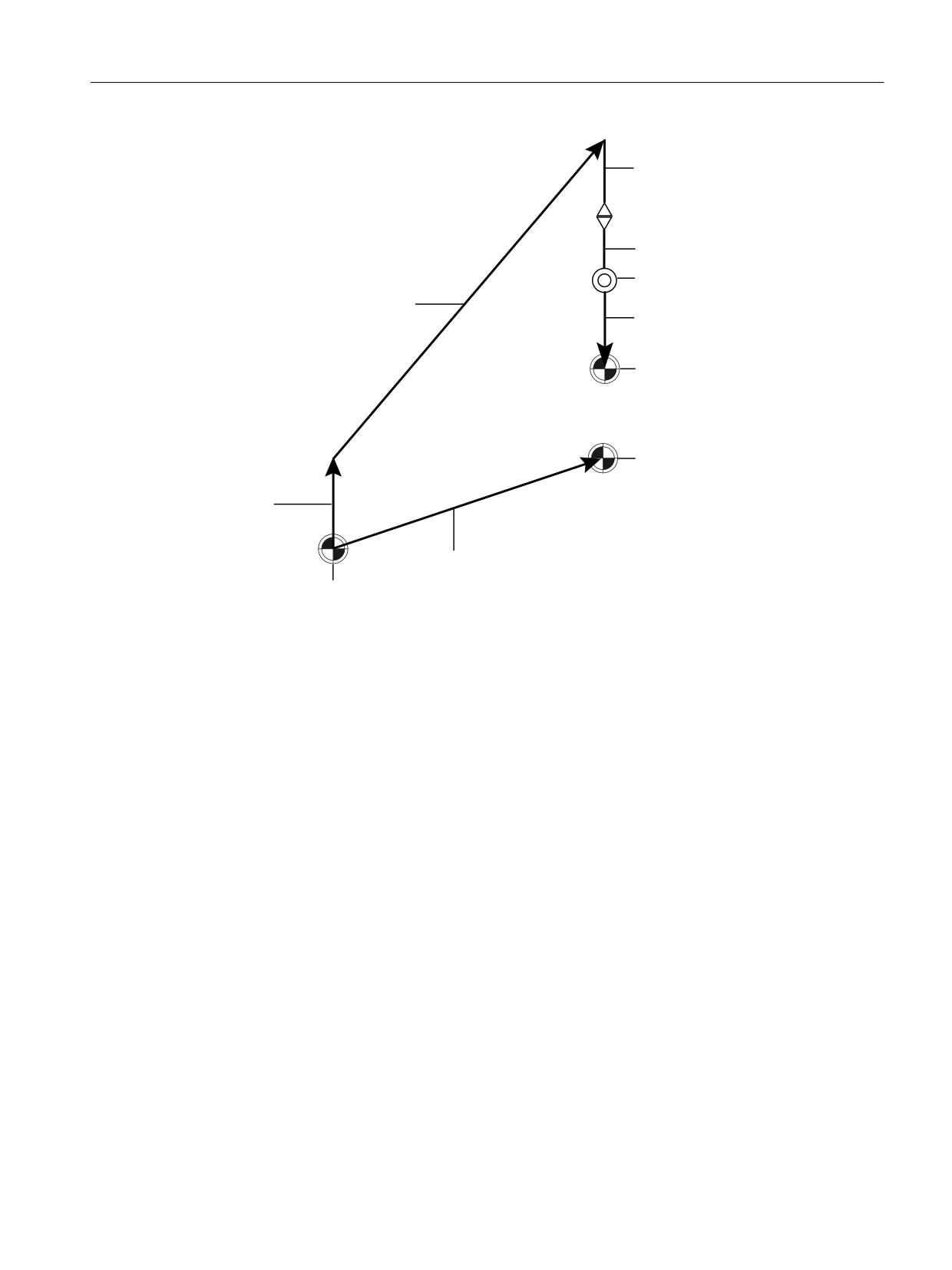
Orientation transformations
6.14 Examples
& D[LV
% D[LV RIIVHW
% D[LV
& D[LV RIIVHW
%DVH WRRO RIIVHW
=HUR SRLQW RI WKH WRRO
FRRUGLQDWH V\VWHP
=HUR SRLQW RI WKH
ZRUNSLHFH FRRUGLQDWH
; < = D[HV
V\VWHP
ZLWK
;
<
=
7DEOH RIIVHW
=HUR SRLQW RI WKH ZRUOG
FRRUGLQDWH V\VWHP
Figure 6-38
Example kinematics for dynamic orientation transformation
The kinematics is created in several steps:
• The two root elements of the kinematic chain are defined:
- $NK_NEXT\[KIE_CNTR] = "X axis"; chain points to the tool reference point.
- $NK_PARALLEL\[KIE_CNTR] = "Table offset"; chain points to the workpiece
reference point.
• The three mutually perpendicular linear axes X, Y and Z are defined starting from the zero
point of the world coordinate system.
- In the rotation vectors $NK_OFF_DIR, which define the axis directions, only the
individual component that is not equal to zero is described. All of the linear axes have their
origin in the same point, because no constant elements are defined between the
individual axes and no zero point offsets have been specified for the axes either.
• The C axis offset is a constant element, which defines the distance between the linear axes
X, Y, Z and the first rotary axis (C axis). The C axis is a rotary axis which points in the Z direction.
• The B axis offset is a constant element, to which the B axis connects.
• The conclusion is formed by the constant offset "Basetool".
• The kinematic chain to the workpiece reference point is formed by the constant
element "Table offset" of the type Offset.
Transformations
Function Manual, 10/2020, 6FC5397-5GP40-0BA1
353
Orientation transformations
6.14 Examples
• The following orientation axes are defined:
- C axis
- B axis
• The following linear compensating axes are defined:
- X axis
- Y axis
- Z axis
Transformations
354
Function Manual, 10/2020, 6FC5397-5GP40-0BA1
Orientation transformations
6.14 Examples
6.14.1.2
Part program for TRAORI_DYN
Program code "5-axis transformation C-B"
;===========================================================
; Definitions
;===========================================================
N10 DEF INT KIE_CNTR = 0
; counter for elements of the kin. chains
;===========================================================
; deletion of all transformation data sets and kinematic chain elements
;===========================================================
N20 IF (DELOBJ(“TRAFO_DATA”) < 0)
N30
SETAL(61000)
N40 ENDIF
N50 IF (DELOBJ(“KIN_CHAIN_ELEM”) < 0)
N60
SETAL(61001)
N70 ENDIF
;===========================================================
; definition of the root element and of the kinematic chain to the tool
reference point
;===========================================================
N80 $NK_NAME[KIE_CNTR]
= "ROOT"
N90 $NK_TYPE[KIE_CNTR]
= "OFFSET"
N100 $NK_NEXT[KIE_CNTR]
= "X axis"
N110 $NK_PARALLEL[KIE_CNTR]
= "Table offset"
N120 KIE_CNTR = KIE_CNTR + 1
;===========================================================
; Definition of the linear axis in X direction
;===========================================================
N130 $NK_NAME[KIE_CNTR]
= "X axis"
N140 $NK_TYPE[KIE_CNTR]
= "AXIS_LIN"
N150 $NK_NEXT[KIE_CNTR]
= "Y axis"
N160 $NK_AXIS[KIE_CNTR]
= "X1"
N170 $NK_OFF_DIR[KIE_CNTR,0]
= 1.0
N180 KIE_CNTR = KIE_CNTR + 1
;===========================================================
; definition of the linear axis in Y direction
;===========================================================
N190 $NK_NAME[KIE_CNTR]
= "Y axis"
N200 $NK_TYPE[KIE_CNTR]
= "AXIS_LIN"
N210 $NK_NEXT[KIE_CNTR]
= "Z axis"
N220 $NK_AXIS[KIE_CNTR]
= "Y1"
N230 $NK_OFF_DIR[KIE_CNTR,1]
= 1.0
N240 KIE_CNTR = KIE_CNTR + 1
;===========================================================
; Definition of the linear axis in Z direction
;===========================================================
N250 $NK_NAME[KIE_CNTR]
= "Z axis"
N260 $NK_TYPE[KIE_CNTR]
= "AXIS_LIN"
N270 $NK_NEXT[KIE_CNTR]
= "C axis offset"
N280 $NK_AXIS[KIE_CNTR]
= "Z1"
N290 $NK_OFF_DIR[KIE_CNTR,2]
= 1.0
N300 KIE_CNTR = KIE_CNTR + 1
;===========================================================
; definition of the distance between the linear axes and the first rotary
axis
Transformations
Function Manual, 10/2020, 6FC5397-5GP40-0BA1
355
Orientation transformations
6.14 Examples
Program code "5-axis transformation C-B"
;===========================================================
N310 $NK_NAME[KIE_CNTR]
= "C axis offset"
N320 $NK_TYPE[KIE_CNTR]
= "OFFSET"
N330 $NK_NEXT[KIE_CNTR]
= "C axis"
N340 $NK_OFF_DIR[KIE_CNTR,0]
= 200.0
N350 $NK_OFF_DIR[KIE_CNTR,2]
= 300.0
N360 KIE_CNTR = KIE_CNTR + 1
;===========================================================
; definition of the C axis in the Z direction - refers to axis C1
;===========================================================
N370 $NK_NAME[KIE_CNTR]
= "C axis"
N380 $NK_TYPE[KIE_CNTR]
= "AXIS_ROT"
N390 $NK_NEXT[KIE_CNTR]
= "B axis offset"
N400 $NK_AXIS[KIE_CNTR]
= "C1"
N410 $NK_OFF_DIR[KIE_CNTR,2]
= 1.0
N420 KIE_CNTR = KIE_CNTR + 1
;===========================================================
; definition of the B axis with an offset between the B and C axes
;===========================================================
N430 $NK_NAME[KIE_CNTR]
= "B axis offset"
N440 $NK_TYPE[KIE_CNTR]
= "OFFSET"
N450 $NK_NEXT[KIE_CNTR]
= "B axis"
N460 $NK_OFF_DIR[KIE_CNTR,2]
= -150.0
N470 KIE_CNTR = KIE_CNTR + 1
N480 $NK_NAME[KIE_CNTR]
= "B axis"
N490 $NK_TYPE[KIE_CNTR]
= "AXIS_ROT"
N500 $NK_NEXT[KIE_CNTR]
= "Base tool"
N510 $NK_AXIS[KIE_CNTR]
= "B1"
N520 $NK_OFF_DIR[KIE_CNTR,0]
= 1.0
N530 KIE_CNTR = KIE_CNTR + 1
;===========================================================
; conclusion of the kinematic chain with an offset
;===========================================================
N540 $NK_NAME[KIE_CNTR]
= "Base tool"
N550 $NK_TYPE[KIE_CNTR]
= "OFFSET"
N560 $NK_NEXT[KIE_CNTR]
= “”
N570 $NK_OFF_DIR[KIE_CNTR,2]
= -50.0
;===========================================================
; definition of the kinematic chain to the table reference point
;===========================================================
N580 KIE_CNTR = KIE_CNTR + 1
N590 $NK_NAME[KIE_CNTR]
= "Table offset"
N600 $NK_TYPE[KIE_CNTR]
= "OFFSET"
N610 $NK_OFF_DIR[KIE_CNTR,0] = 200.0
N620 $NK_OFF_DIR[KIE_CNTR,2]
= 100.0
N630 KIE_CNTR = KIE_CNTR + 1
;===========================================================
; Definition of the transformation (TRAORI)
;===========================================================
N640 $NT_NAME[1]
= "5-axis transformation C-B"
N650 $NT_T_CHAIN_LAST_ELEM[1] = "base tool"
N660 $NT_P_CHAIN_LAST_ELEM[1] = "Table offset"
N670 $NT_TRAFO_TYPE[1]
= “TRAORI_DYN”
;===========================================================
Transformations
356
Function Manual, 10/2020, 6FC5397-5GP40-0BA1
Orientation transformations
6.14 Examples
Program code "5-axis transformation C-B"
; Definition of the orientation and geometry axes
;===========================================================
N680 $NT_ROT_AX_NAME[1,0]
= "C axis"
N690 $NT_ROT_AX_NAME[1,1]
= "B axis"
N700 $NT_GEO_AX_NAME[1,0]
= "X axis"
N710 $NT_GEO_AX_NAME[1,1]
= "Y axis"
N720 $NT_GEO_AX_NAME[1,2]
= "Z axis"
;========================= END ===========================
6.14.2
Example of a 5-axis transformation
CHANDATA(1)
$MA_IS_ROT_AX[AX5] = TRUE
$MA_SPIND_ASSIGN_TO_MACHAX[AX5] = 0
$MA_ROT_IS_MODULO[AX5]=0
;-----------------------------------------------------------------------------------------------------
; general 5-axis transformation
;
; kinematics:
1st rotary axis is parallel to Z
;
2nd rotary axis is parallel to X
;
Movable tool
;-----------------------------------------------------------------------------------------------------
$MC_TRAFO_TYPE_1 = 20
$MC_ORIENTATION_IS_EULER = TRUE
$MC_TRAFO_AXES_IN_1[0] = 1
$MC_TRAFO_AXES_IN_1[1] = 2
$MC_TRAFO_AXES_IN_1[2] = 3
$MC_TRAFO_AXES_IN_1[3] = 4
$MC_TRAFO_AXES_IN_1[4] = 5
$MC_TRAFO_GEOAX_ASSIGN_TAB_1[0]=1
$MC_TRAFO_GEOAX_ASSIGN_TAB_1[1]=2
$MC_TRAFO_GEOAX_ASSIGN_TAB_1[2]=3
$MC_TRAFO5_PART_OFFSET_1[0] = 0
$MC_TRAFO5_PART_OFFSET_1[1] = 0
$MC_TRAFO5_PART_OFFSET_1[2] = 0
Transformations
Function Manual, 10/2020, 6FC5397-5GP40-0BA1
357
Orientation transformations
6.14 Examples
$MC_TRAFO5_ROT_AX_OFFSET_1[0] = 0
$MC_TRAFO5_ROT_AX_OFFSET_1[1] = 0
$MC_TRAFO5_ROT_SIGN_IS_PLUS_1[0] = TRUE
$MC_TRAFO5_ROT_SIGN_IS_PLUS_1[1] = TRUE
$MC_TRAFO5_NON_POLE_LIMIT_1 = 2.0
$MC_TRAFO5_POLE_LIMIT_1 = 2.0
$MC_TRAFO5_BASE_TOOL_1[0] = 0.0
$MC_TRAFO5_BASE_TOOL_1[1] = 0.0
$MC_TRAFO5_BASE_TOOL_1[2] = 5,0
$MC_TRAFO5_JOINT_OFFSET_1[0] = 0.0
$MC_TRAFO5_JOINT_OFFSET_1[1] = 0.0
$MC_TRAFO5_JOINT_OFFSET_1[2] = 0.0
CHANDATA(1)
M17
Program example for general 5-axis transformation:
Program code
Comment
; Definition of tool T1
$TC_DP1[1,1] = 10
;Type
$TC_DP2[1,1] = 0
$TC_DP3[1,1] = 20.
;z length compensation vector G17
$TC_DP4[1,1] = 0.
;y
$TC_DP5[1,1] = 0.
;x
$TC_DP6[1,1] = 0.
;Radius
$TC_DP7[1,1] = 0
$TC_DP8[1,1] = 0
$TC_DP9[1,1] = 0
$TC_DP10[1,1] = 0
$TC_DP11[1,1] = 0
$TC_DP12[1,1] = 0
Approach initial position:
N100 G1 x1 y0 z0 a0 b0 F20000 G90 G64 T1 D1 G17 ADIS=.5
ADISPOS=3
Orientation vector programming:
N110 TRAORI(1)
N120 ORIWKS
N130 G1 G90
N140 a3 = 0 b3 = 0 c3 = 1 x0
Transformations
358
Function Manual, 10/2020, 6FC5397-5GP40-0BA1
Orientation transformations
6.14 Examples
N150 a3 = 0 b3 =-1 c3 = 0
N160 a3 = 1 b3 = 0 c3 = 0
N170 a3 = 1 b3 = 0 c3 = 1
N180 a3 = 0 b3 = 1 c3 = 0
N190 a3 = 0 b3 = 0 c3 = 1
Euler angles program:
N200 ORIMKS
N210 G1 G90
N220 a2 = 0 b2 = 0 x0
N230 a2 = 0 b2 = 90
N240 a2 = 90 b2 = 90
N250 a2 = 90 b2 = 45
N260 a2 = 0 b2 =-90
N270 a2 = 0 b2 = 0
Axis programming:
N300 a0 b0 x0
N310 a45
N320 b30
TOFRAME:
N400 G0 a90 b90 x0 G90
N410 TOFRAME
N420 z5
N430 x3 y5
N440 G0 a0 b0 x1 y0 z0 G90
N500 TRAFOOF
m30
6.14.3
Example of a 3-axis and 4-axis transformation
6.14.3.1
Example of a 3-axis transformation
Example: For the schematically represented machine (see "3-axis and 4-axis transformations
(Page 252)"), the 3-axis transformation can be configured as follows:
Program code
Comment
$MC_TRAFO_TYPE_n = 18
$MC_TRAFO_GEOAX_ASSIGN_TAB_n[0] = 1
Assignment of channel axes to geometry
axes
Transformations
Function Manual, 10/2020, 6FC5397-5GP40-0BA1
359

Orientation transformations
6.14 Examples
Program code
Comment
$MC_TRAFO_GEOAX_ASSIGN_TAB_n[1] = 0
$MC_TRAFO_GEOAX_ASSIGN_TAB_n[2] = 3
$MC_TRAFO_AXES_IN_n[0] = 1
X axis is channel axis 1
$MC_TRAFO_AXES_IN_n[1] = 0
Y axis is not used
$MC_TRAFO_AXES_IN_n[2] = 3
Z axis is channel axis 3
$MC_TRAFO_AXES_IN_n[4] = 0
There is no second rotary axis
6.14.3.2
Example of a 4-axis transformation
Example: For the schematically represented machine (see "3-axis and 4-axis transformations
(Page 252)"), however, with an additional axis (Y), the 4-axis transformation can be configured
as follows:
Program code
Comment
$MC_TRAFO_TYPE_n = 18
$MC_TRAFO_GEOAX_ASSIGN_TAB_n[0] = 1
$MC_TRAFO_GEOAX_ASSIGN_TAB_n[1] = 2
$MC_TRAFO_GEOAX_ASSIGN_TAB_n[2] = 3
$MC_TRAFO_AXES_IN_n[0] = 1
X axis is channel axis 1
$MC_TRAFO_AXES_IN_n[1] = 2
Y axis is channel axis 2
$MC_TRAFO_AXES_IN_n[2] = 3
Z axis is channel axis 3
$MC_TRAFO_AXES_IN_n[4] = 0
There is no second rotary axis
6.14.4
Example of a universal milling head
General
The following two subsections show the main steps which need to be taken in order to activate
a transformation for the universal milling head.
Machine data
; machine kinematics CA' with tool orientation in zero position in the z direction
$MC_TRAFO_TYPE_1 = 148
$MC_TRAFO_GEOAX_ASSIGN_TAB_1[0] = 1
$MC_TRAFO_GEOAX_ASSIGN_TAB_1[1] = 2
$MC_TRAFO_GEOAX_ASSIGN_TAB_1[2] = 3
Transformations
360
Function Manual, 10/2020, 6FC5397-5GP40-0BA1
Orientation transformations
6.14 Examples
;angle of second rotary axis
$MC_TRAFO5_NUTATOR_AX_ANGLE_1 = 45
Program
Program code
; Definition of tool T1
$TC_DP1[1,1] = 120
;Type
$TC_DP2[1,1] = 0
;
$TC_DP3[1,1] = 20
;Z length compensation vector G17
$TC_DP4[1,1] = 8.
;Y
$TC_DP5[1,1] = 5.
;X
TRAORI(1)
;Activation of the transformation
ORIMKS
;Orientation reference to MCS
G0 X1 Y0 Z0 A0 B0 F20000 G90 G64 T1 D1 G17
;Programming of direction vector
G1 G90
a3 = 0 b3 = 1 c3 = 0
;Programming in Euler angles
G1 G90
a2 = 0 b2 = 0 X0
;Programming of rotary axis motion
G1 X10 Y5 Z20 A90 C90
m30
Additional information
Programming Manual NC Programming
6.14.5
Example for orientation axes
Example 1:
3 orientation axes for the 1st orientation transformation for kinematics with 6 transformed axes.
Rotation must be done in the following sequence:
• firstly about the Z axis,
• then about the Y axis and
• finally about the Z axis again.
Transformations
Function Manual, 10/2020, 6FC5397-5GP40-0BA1
361
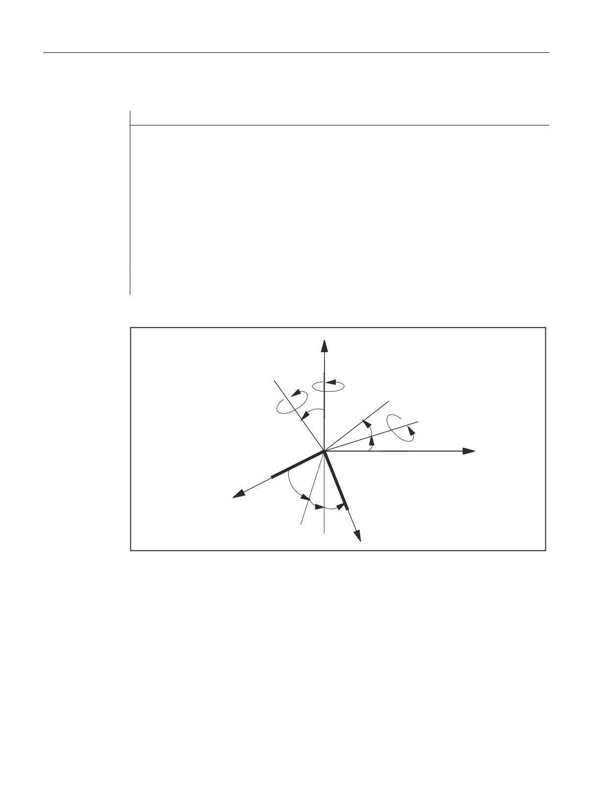
Orientation transformations
6.14 Examples
The tool vector must point in the X direction.
Program code
Comment
CHANDATA(1)
$MC_TRAFO5_TOOL_VECTOR_1=0
;Tool vector in X direction
$MC_TRAFO5_ORIAX_ASSIGN_TAB_1[0]=4
;Channel index 1st orient. axis
$MC_TRAFO5_ORIAX_ASSIGN_TAB_1[1]=5
;Channel index 2nd orient. axis
$MC_TRAFO5_ORIAX_ASSIGN_TAB_1[2]=6
;Channel index 3rd orient. axis
$MC_ORIAX_TURN_TAB_1[0]=3
;Z direction
$MC_ORIAX_TURN_TAB_1[1]=2
;Y direction
$MC_ORIAX_TURN_TAB_1[2]=3
;Z direction
CHANDATA(1)
M17
=
=
=
=
$
<
&
%
&
<
<
%
$
<
;VWDUW
$
;WDUJHW
;
%
&
;
;
;
Figure 6-39
3 orientation axes for the 1st orientation transformation for kinematics with 6 transformed
axes
Example 2:
3 orientation axes for the 2nd orientation transformation for kinematics with 5 transformed
axes. Rotation must be done in the following sequence:
• firstly about the X axis,
• then about the Y axis and
• finally about the Z axis.
Transformations
362
Function Manual, 10/2020, 6FC5397-5GP40-0BA1
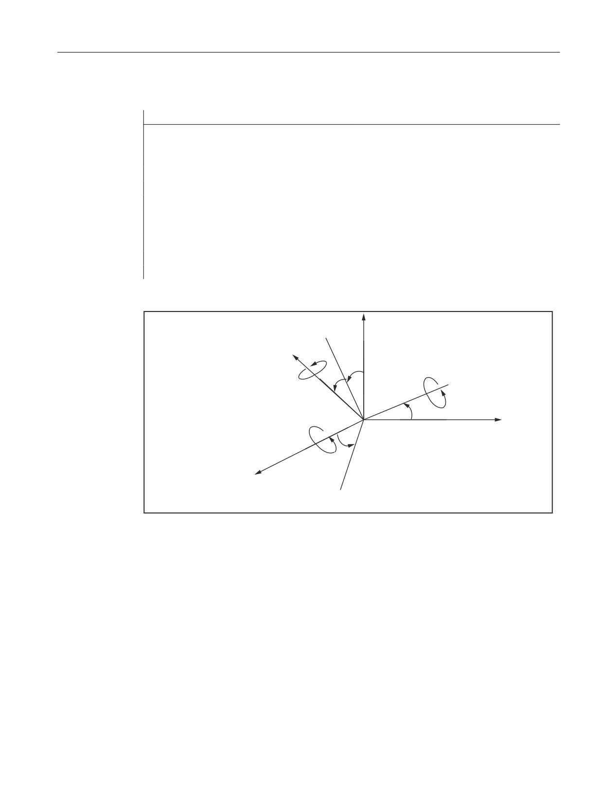
Orientation transformations
6.14 Examples
The tool vector must point in the Z direction.
Program code
Comment
CHANDATA(1)
$MC_TRAFO5_TOOL_VECTOR_2=2
;Tool vector in Z direction
$MC_TRAFO5_ORIAX_ASSIGN_TAB_1[0]=4
;Channel index 1st orient. axis
$MC_TRAFO5_ORIAX_ASSIGN_TAB_1[1]=5
;Channel index 2nd orient. axis
$MC_TRAFO5_ORIAX_ASSIGN_TAB_1[2]=0
;Channel index 3rd orient. axis
$MC_ORIAX_TURN_TAB_1[0]=1
;X direction
$MC_ORIAX_TURN_TAB_1[1]=2
;Y direction
$MC_ORIAX_TURN_TAB_1[2]=3
;Z direction
CHANDATA(1)
M17
Z
Z’
C2
Z’’
A2
B2
Y’
Y’’
B2
A2
Y
B2
A2
X
X’
X’’
Figure 6-40
3 orientation axes for the 2nd orientation transformation for kinematics with 5 transformed
axes
The rotation through angle C2 about the Z" axis is omitted in this case, because the tool vector
orientation can be determined solely from angles A2 and B2 and no further degree of freedom
is available on the machine.
Additional information
"NC Programming" Programming Manual
Transformations
Function Manual, 10/2020, 6FC5397-5GP40-0BA1
363
Orientation transformations
6.14 Examples
6.14.6
Examples for orientation vectors
6.14.6.1
Example for polynomial interpretation of orientation vectors
Orientation vector in Z-X plane
The orientation vector is programmed directly in the examples below. The resulting movements
of the rotary axes depend on the particular kinematics of the machine.
Program code
Comment
N10 TRAORI
N20 POLY
; Polynomial interpolation is possible.
N30 A3=0 B3=0 C3=1
; Orientation in +Z direction (start vector)
N40 A3=1 B3=0 C3=0
; Orientation in +X direction (end vector)
In N40, the orientation vector is rotated in the Z-X plane which is spanned by the start and end
vector. Here, the PHI angle is interpolated in a line in this plane between the values 0 and 90
degrees (large circle interpolation).
The additional specification of the polynomials for the two angles PHI and PSI means that the
interpolated orientation vector can lies anywhere between the start and end vector.
PHI angle using polynomial PHI
In contrast to the example above, the PHI angle is interpolated using the polynomial PHI(u) =
(90-10)u + 10*u2 between the values 0 and 90 degrees.
The angle PSI is not equal to zero and is interpolated according to the following polynomial:
PSI(u) = -10*u + 10*u2
The maximum "tilt" of the orientation vector from the plane between the start and end vector
is obtained in the middle of the block (u = 1/2).
Program code
Comment
N10 TRAORI
N20 POLY
; Polynomial interpolation is possible.
N30 A3=0 B3=0 C3=1
; Orientation in +Z direction (start vector)
N40 A3=1 B3=0 C3=0
PO[PHI]=(10) ; in +X direction (end vector)
PO[PSI]=(10)
Transformations
364
Function Manual, 10/2020, 6FC5397-5GP40-0BA1
Orientation transformations
6.14 Examples
6.14.6.2
Example of rotations of orientation vector
Rotations with angle of rotation THETA
In the following example, the angle of rotation is interpolated in linear fashion from starting
value 0 degrees to end value 90 degrees. The angle of rotation changes according to a parabola
or a rotation can be executed without a change in orientation. tool orientation is rotated from
the Y direction to the X direction.
Program code
Comment
N10 TRAORI
; Activation of orientation transformation
N20 G1 X0 Y0 Z0 F5000
;
; Tool orientation
N30 A3=0 B3=0 C3=1 THETA=0
; In Z direction with angle of rotation 0
N40 A3=1 B3=0 C3=0 THETA=90
; In X direction and rotation
; By 90 degrees
N50 A3=0 B3=1 C3=0 PO[THT]=(180,90)
; In Y direction and rotation
; To 180 degrees
N60 A3=0 B3=1 C3=0 THETA=IC(-90)
; Remains constant and rotation
; To 90 degrees
N70 ORIROTT
; Angle of rotation relative to
; change in orientation.
N80 A3=1 B3=0 C3=0 THETA=30
; Rotation vector in angle
; 30 degrees to X-Y plane.
N40 Linear interpolation of angle of rotation from starting value 0 degrees to end value 90
degrees.
N50 The angle of rotation changes from 90 degrees to 180 degrees in accordance with the
parabola.
θ(u) = 90 + u2
N60 A rotation can also be programmed without a change in orientation taking place.
N80 Tool orientation is rotated from the Y direction to the X direction. The change in orientation
takes place in the X-Y plane and the rotation vector describes an angle of 30 degrees to this plane.
6.14.7
Examples for generic axis transformations
6.14.7.1
Example of generic 5-axis transformation
The following example is based on a machine with rotatable tool on which the first rotary axis
is a C axis and the second a B axis (CB kinematics). The basic orientation defined in the machine
data is the bisecting line between the X and Z axes.
Transformations
Function Manual, 10/2020, 6FC5397-5GP40-0BA1
365
Orientation transformations
6.14 Examples
Relevant machine data is as follows:
CHANDATA(1)
$MC_TRAFO_TYPE_1 = 24
; General 5-axis transformation
; Rotatable tool
$MC_TRAFO5_AXIS1_1[0] = 0.0
$MC_TRAFO5_AXIS1_1[1] = 0.0
$MC_TRAFO5_AXIS1_1[2] = 1,0
; 1. Rotary axis is parallel to Z.
$MC_TRAFO5_AXIS2_1[0] = 0.0
$MC_TRAFO5_AXIS2_1[1] = 1,0
$MC_TRAFO5_AXIS2_1[2] = 0.0
; 2. Rotary axis is parallel to Y.
$MC_TRAFO5_BASE_ORIENT_1[0] = 1.0
$MC_TRAFO5_BASE_ORIENT_1[1] = 0,0
$MC_TRAFO5_BASE_ORIENT_1[2] = 1.0
M30
Example program:
Program code
Comment
N10
$TC_DP1[1,1] = 120
; End mill
N20
$TC_DP3[1,1]= 0
; Length offset vector
N30
N40
; Definition of tool carrier
N50
$TC_CARR7[1] = 1
; Component of the 1st rotary axis
; In the X direction
N60
$TC_CARR11[1] = 1
; Component of the 2nd rotary axis
; In the Y direction
N70
$TC_CARR13[1] = -45
; Angle of rotation of 1st axis
N80
$TC_CARR14[1] = 0
; Angle of rotation of 2nd axis
N90
N100
X0 Y0 Z0 B0 C0 F10000 ORIWKS G17
N110
TRAORI()
; Selection of basic transformation orientation
; from the machine data
N120
C3=1
; Orientation parallel to Z
; Set → B-45 C0
N130
T1 D1
; Basic orientation is now parallel to Z
N140
C3=1
; Orientation parallel to Z
; Set → B0 C0
N150
G19
; Basic orientation is now parallel to X
N160
C3=1
; Orientation parallel to Z
; Set → B-90 C0
N170
G17 TCARR=1 TCOABS
; Basic orientation is now angle-
; halving Y-Z
N180
A3=1
; Orientation parallel to X
; Set → B-90 C-135
N190
B3=1 C3=1
; Orientation parallel to
Transformations
366
Function Manual, 10/2020, 6FC5397-5GP40-0BA1

Orientation transformations
6.14 Examples
Program code
Comment
; basic orientation → B0 C0
N200
TRAORI(,2.0, 3.0, 6.0)
; Pass basic orientation in call
N210
A3=2 B3=3 C3=6
; Orientation parallel to
; basic orientation → B0 C0
N220
TOFRAME
; Z axis points in the direction
; of the orientation
N230
G91 Z7
; 7 mm in new Z direction
; Traverse → X2 Y3 Z6
N240
C3=1
; Orientation parallel to
; New Z axis → B0 C0
N250
M30
6.14.7.2
Example of a generic 6-axis transformation
Call with parameterization using parameters
Activation of a 6-axis transformation with subsequent orientation changes and traversing:
Program code
Comment
N10 A0 B0 X0 Y0 Z0
N20 TRAORI(1, ,,, 0,0,0, 0,1,0)
; Selection using parameters:
; parameters 5, 6, 7: Orientation vector
; Parameters 8, 9, 10: Orientation normal vec-
tor
N30 T1 D1 X10 Y20 Z30 A3=0.5
; Orientation change, rotation
C3=1 BN3=1 ORIPLANE ORIWKS
; and traversing motion
N40 B3=0.5 C3=1 AN3=-1
; Rotation, constant orientation
M30
Call with parameterization using tool data
Defining a tool, where the orientation, with an orientation vector of (1.0 ; 0.0 ; 0.5) deviates from
the standard. For G17, the orientation vector is in the X-Z plane, and starting from the X axis in
the direction of the Z vector, inclined by 26.565 degrees:
tan-1($TC_DPV5[ 2, 2 ] / $TC_DPV3[ 2, 2 ]) = tan-1(0.5 / 1.01) = tan-1(0.5) = 26.565°
The orientation normal vector is also specified. As only $TC_DPVN4[2,2] is not equal to zero, it
points in the Y direction. Orientation vector and orientation normal vector are perpendicular to
one another. Orthogonalization is not necessary. The programmed orientation normal vector is
not modified.
Program code
Comment
N100 $TC_DP1[2,2]=120
; End mill
N110 $TC_DP3[2,2]= 20
; Length offset vector
N120 $TC_DPV[2,2]= 0
; Tool cutting edge orientation
; Orientation vector tool cutting edge
N130 $TC_DPV3[2,2]= 1
; X component
Transformations
Function Manual, 10/2020, 6FC5397-5GP40-0BA1
367

Orientation transformations
6.14 Examples
Program code
Comment
N140 $TC_DPV4[2,2]= 0
; Y component
N150 $TC_DPV5[2,2]= 0.5
; Z component
; Orientation normal vector
N160 $TC_DPVN3[2,2]= 0
; X component
N170 $TC_DPVN4[2,2]= 1
; Y component
N180 $TC_DPVN5[2,2]= 0
; Z component
N200 TRAORI( )
; Call with basic orientation
N210 A3=5 C3=10 BN3=1
; Bring rotary axes into the initial state
N220 C3=1
; Orientation in the Z direction ⇒
; Tool rotated through 26.565 degrees
N230 THETA=IC(90)
; Orientation normal vector incremental
; Rotated through 90 degrees. Vector points in nega-
tive X direction
N240 M30
6.14.7.3
Example of a generic 7-axis transformation
Example of a generic 7-axis transformation
Activation of a 7-axis transformation with subsequent orientation changes and traversing:
Program
Comment
N10 TRAFOOF
N20 a0 b0 c0 x0 y0 z0 e=0
N30 $MC_TRAFO5_AXIS1_1[2] = 1
;
1. Rotary axis shows in Z direction
N40 $MC_TRAFO5_AXIS1_2[0] = 1
;
2. Rotary axis shows in X direction
N50 $MC_TRAFO5_AXIS1_3[2] = 1
;
3. Rotary axis shows in Z direction
N60 $MC_TRAFO7_EXT_AXIS1_1[0] = 1
;
7. Axis shows in X direction
N70 $MC_TRAFO_BASE_ORIENT_1[2] = 1
;
Orientation vector
N80 $MC_TRAFO_BASE_ORIENT_NORMAL_1[1] = 1
;
Orientation normal vector
N90 NEWCONF
N100 traori()
N110 G1 t1 d1 x10 y0 z50 c3=1 an3=1 bn3=1
orivect oriwks G19 F10000
N120 G2 y50 z0 b3=1 e=DC(90) CR=50
;
1. Quadrant
N130 G2 y0 z-50 c3=-1 e=DC(180) CR=50
;
2. Quadrant
N140 G2 y-50 z0 b3=-1 e=DC(270) CR=50
;
3. Quadrant
N150 G2 y0 z50 c3=1 e=DC(0) CR=50
;
4. Quadrant
N200 M30
Transformations
368
Function Manual, 10/2020, 6FC5397-5GP40-0BA1

Orientation transformations
6.15 Data lists
Note
While traversing the quadrant in the example, only the 7th axis turns by 360 degrees. The
machine remains in the fixed position.
6.14.7.4
Example for the modification of rotary axis motion
The machine is a 5-axis machine of machine type 1 (two-axis swivel head with CA kinematics)
on which both rotary axes rotate the tool (transformation type 24). The first rotary axis is a
modulo axis parallel to Z (C axis); the second rotary axis is parallel to Y (B axis) and has a
traversing range from -5 degrees to +185 degrees.
To allow modification at any time, the following machine data has the value 2:
MD21180 $MC_ROT_AX_SWL_CHECK_MODE (check software limits for orientation axes)
N10 X0 Y0 Z0 B0 C0
N20 TRAORI( )
; basic orientation 5-axis transformation
N30 B-1 C10
; Rotary axis positions B-1 and C10
N40 A3=-1 C3=1 ORIWKS
; large circle interpolation in WCS
N50 M30
At the start of block N40 in the example program, the machine is positioned at rotary axis
positions B-1 C10. The programmed end orientation can be achieved with either of the axis
positions B-45 C0 (1st solution) or B45 C180 (2nd solution).
The first solution is selected initially, because it is nearest to the starting orientation and, unlike
the second solution, can be achieved using large circle interpolation (ORIWKS). However, this
position cannot be reached because of the axis limits of the B axis.
The second solution is therefore used instead, i.e. the end position is B45 C180. The end
orientation is achieved by axis interpolation. The programmed orientation path cannot be
followed.
6.15
Data lists
6.15.1
Machine data
6.15.1.1
General machine data
Number Identifier: $MN_
Description
10620
EULER_ANGLE_NAME_TAB
Name of Euler angles or names of orientation axes
10630
NORMAL_VECTOR_NAME_TAB
Name of normal vectors
10640
DIR_VECTOR_NAME_TAB
Name of direction vectors
Transformations
Function Manual, 10/2020, 6FC5397-5GP40-0BA1
369

Orientation transformations
6.15 Data lists
Number Identifier: $MN_
Description
10642
ROT_VECTOR_NAME_TAB
Name of rotation vectors
10644
INTER_VECTOR_NAME_TAB
Name of intermediate vector components
10646
ORIENTATION_NAME_TAB
Identifier for programming a 2nd orientation path
10648
NUTATION_ANGLE_NAME
Name of orientation angle
10670
STAT_NAME
Name of position information
10672
TU_NAME
Name of position information of the axes
10674
PO_WITHOUT_POLY
Permits programming of PO[ ] without POLY having to be
active
6.15.1.2
Channelspecific machine data
Number
Identifier: $MC_
Description
20150
GCODE_RESET_VALUES[n]
Reset G groups
20152
GCODE_RESET_MODE[n]
Setting after RESET/end of part program
20482
COMPRESS_MODE
Mode of the compressor
20621
HANDWH_ORIAX_MAX_INCR_SIZE
Limitation of handwheel increment
20623
HANDWH_ORIAX_MAX_INCR_VSIZE
Orientation velocity overlay
21094
ORIPATH_MODE
Setting for path relative orientation
21100
ORIENTATION_IS_EULER
Angle definition for orientation programming
21102
ORI_DEF_WITH_G_CODE
Definition of orientation angles A2, B2, C2
21104
ORI_IPO_WITH_G_CODE
Definition of interpolation type for orientation
21106
CART_JOG_SYSTEM
Coordinate system for Cartesian JOG
21108
POLE_ORI_MODE
Behavior during large circle interpolation at pole position
21120
ORIAX_TURN_TAB_1[n]
Assignment of rotation of orientation axes about the ref-
erence axes, definition 1 [n = 0..2]
21130
ORIAX_TURN_TAB_2[n]
Assignment of rotation of orientation axes about the ref-
erence axes, definition 2 [n = 0..2]
21132
ORI_DISP_IS_MODULO[n]
Modulo display of the orientation axes positions [n = 0..2]
21134
ORI_DISP_MODULO_RANGE
Size of the module range for the display of the orienta-
tion axes
21136
ORI_DISP_MODULO_RANGE_START
Starting position of the module range for the display of
the orientation axes
21150
JOG_VELO_RAPID_ORI[n]
Rapid traverse in jog mode for orientation axes in the
channel [n = 0..2]
21155
JOG_VELO_ORI[n]
Orientation axis velocity in jog mode [n = 0..2]
21160
JOG_VELO_RAPID_GEO[n]
Rapid traverse in jog mode for geometry axes in the
channel [n = 0..2]
21165
JOG_VELO_GEO[n]
Geometry axis velocity in jog mode [n = 0..2]
21170
ACCEL_ORI[n]
Acceleration for orientation axes [n = 0..2]
21180
ROT_AX_SWL_CHECK_MODE
Check software limits for orientation axes
21186
TOCARR_ROT_OFFSET_FROM_FR
Offset of TOCARR rotary axes
21190
TOFF_MODE
Operation of online offset in tool direction
Transformations
370
Function Manual, 10/2020, 6FC5397-5GP40-0BA1

Orientation transformations
6.15 Data lists
Number
Identifier: $MC_
Description
21194
TOFF_VELO
Speed of online offset in tool direction
21196
TOFF_ACCEL
Acceleration of online offset in tool direction
24100
TRAFO_TYPE_1
Definition of transformation 1 in channel
24110
TRAFO_AXES_IN_1[n]
Axis assignment for transformation 1 [axis index]
24120
TRAFO_GEOAX_ASSIGN_TAB_1[n]
Assignment geometry axis to channel axis for transfor-
mation 1 [geometry no.]
24200
TRAFO_TYPE_2
Definition of transformation 2 in channel
24210
TRAFO_AXES_IN_2[n]
Axis assignment for transformation 2 [axis index]
24220
TRAFO_GEOAX_ASSIGN_TAB_2[n]
Assignment geometry axis to channel axis for transfor-
mation 2 [geometry no.]
24300
TRAFO_TYPE_3
Definition of transformation 3 in channel
24310
TRAFO_AXES_IN_3[n]
Axis assignment for transformation 3 [axis index]
24320
TRAFO_GEOAX_ASSIGN_TAB_3[n]
Assignment geometry axis to channel axis for transfor-
mation 3 [geometry no.]
24400
TRAFO_TYPE_4
Definition of transformation 4 in channel
24410
TRAFO_AXES_IN_4[n]
Axis assignment for transformation 4 [axis index]
24420
TRAFO_GEOAX_ASSIGN_TAB_4[n]
Assignment geometry axis to channel axis for transfor-
mation 4 [geometry no.]
24430
TRAFO_TYPE_5
Definition of transformation 5 in channel
24432
TRAFO_AXES_IN_5[n]
Axis assignment for transformation 5 [axis index]
24434
TRAFO_GEOAX_ASSIGN_TAB_5[n]
Assignment geometry axis to channel axis for transfor-
mation 5 [geometry no.]
24440
TRAFO_TYPE_6
Definition of transformation 6 in channel
24442
TRAFO_AXES_IN_6[n]
Axis assignment for transformation 6 [axis index]
24444
TRAFO_GEOAX_ASSIGN_TAB_6[n]
Assignment geometry axis to channel axis for transfor-
mation 6 [geometry no.]
24450
TRAFO_TYPE_7
Definition of transformation 7 in channel
24452
TRAFO_AXES_IN_7[n]
Axis assignment for transformation 7 [axis index]
24454
TRAFO_GEOAX_ASSIGN_TAB_7[n]
Assignment geometry axis to channel axis for transfor-
mation 7 [geometry no.]
24460
TRAFO_TYPE_8
Definition of transformation 8 in channel
24462
TRAFO_AXES_IN_8[n]
Axis assignment for transformation 8 [axis index]
24464
TRAFO_GEOAX_ASSIGN_TAB_8[n]
Assignment geometry axis to channel axis for transfor-
mation 8 [geometry no.]
24470
TRAFO_TYPE_9
Definition of transformation 9 in channel
24472
TRAFO_AXES_IN_9[n]
Axis assignment for transformation 9 [axis index]
24474
TRAFO_GEOAX_ASSIGN_TAB_9[n]
Assignment geometry axis to channel axis for transfor-
mation 9 [geometry no.]
24480
TRAFO_TYPE_10
Definition of transformation 10 in channel
24482
TRAFO_AXES_IN_10[n]
Axis assignment for transformation 10 [axis index]
24484
TRAFO_GEOAX_ASSIGN_TAB_10[n]
Assignment geometry axis to channel axis for transfor-
mation 10 [geometry no.]
24500
TRAFO5_PART_OFFSET_1[n]
Offset vector for 5-axis transformation 1 [n = 0.. 2]
Transformations
Function Manual, 10/2020, 6FC5397-5GP40-0BA1
371

Orientation transformations
6.15 Data lists
Number
Identifier: $MC_
Description
24510
TRAFO5_ROT_AX_OFFSET_1[n]
Position offset of rotary axis 1/2 for 5-axis transformation
1 [axis no.]
24520
TRAFO5_ROT_SIGN_IS_PLUS_1[n]
Sign of rotary axis 1/2 for 5-axis transformation 1 [axis
no.]
24530
TRAFO5_NON_POLE_LIMIT_1
Definition of pole range for 5-axis transformation 1
24540
TRAFO5_POLE_LIMIT_1
End angle tolerance with interpolation through pole for
5-axis transformation 1
24550
TRAFO5_BASE_TOOL_1[n]
Vector of base tool for activation of 5-axis transformation
1 [n = 0.. 2]
24558
TRAFO5_JOINT_OFFSET_PART_1[n]
Vector of kinematic offset in table for 5-axis transforma-
tion 1 [n = 0.. 2]
24560
TRAFO5_JOINT_OFFSET_1[n]
Vector of kinematic offset for 5-axis transformation 1 [n
= 0.. 2]
24561
TRAFO6_JOINT_OFFSET_2_3_1[n]
Vector of kinematic offset for 6-axis transformation
2_3_1
24562
TRAFO5_TOOL_ROT_AX_OFFSET_1[n]
Offset of focus of 1st 5-axis transformation with swiveled
linear axis.
24564
TRAFO5_NUTATOR_AX_ANGLE_1
Angle of 2nd rotary axis for the universal milling head
24570
TRAFO5_AXIS1_1[n]
Vector for the first rotary axis and the first orientation
transformation. [n = 0.. 2]
24572
TRAFO5_AXIS2_1[n]
Vector for the second rotary axis and the first transfor-
mation [n = 0.. 2]
24673
TRAFO5_AXIS3_1[n]
Direction of third rotary axis for general 6-axis transfor-
mation
(Transformer type 24, 40, 56, 57)
24574
TRAFO5_BASE_ORIENT_1[n]
Basic orientation for the first transformation [n = 0.. 2]
24576
TRAFO6_BASE_ORIENT_NORMAL_1[n]
Tool normal vector for the first transformation [n = 0.. 2]
24580
TRAFO5_TOOL_VECTOR_1
Tool vector direction for the first 5-axis transformation 1
24582
TRAFO5_TCARR_NO_1
TCARR number for the first 5-axis transformation 1
24585
TRAFO5_ORIAX_ASSIGN_TAB_1[n]
Assignment of orientation axes to channel axes for ori-
entation transformation 1 [n = 0.. 2]
24590
TRAFO5_ROT_OFFSET_FROM_FR_2
Offset of transf. rotary axes from WO
24594
TRAFO7_EXT_ROT_AX_OFFSET_1
Angle offset of the 1st external rotary axis
24595
TRAFO7_EXT_AXIS1_1
Direction of the 1st external rotary axis
24600
TRAFO5_PART_OFFSET_2[n]
Offset vector for 5-axis transformation 2 [n = 0.. 2]
24610
TRAFO5_ROT_AX_OFFSET_2[n]
Position offset of rotary axis 1/2 for 5-axis transformation
2 [axis no.]
24620
TRAFO5_ROT_SIGN_IS_PLUS_2[n]
Sign of rotary axis 1/2 for 5-axis transformation 2 [axis
no.]
24630
TRAFO5_NON_POLE_LIMIT_2
Definition of pole range for 5-axis transformation 2
24640
TRAFO5_POLE_LIMIT_2
End angle tolerance with interpolation through pole for
5-axis transformation 2
24650
TRAFO5_BASE_TOOL_2[n]
Vector of base tool with activation of 5-axis transforma-
tion 2 [n = 0.. 2]
24658
TRAFO5_JOINT_OFFSET_PART_2[n]
Vector of kinematic offset in table for 5-axis transforma-
tion 2 [n = 0.. 2]
Transformations
372
Function Manual, 10/2020, 6FC5397-5GP40-0BA1

Orientation transformations
6.15 Data lists
Number
Identifier: $MC_
Description
24660
TRAFO5_JOINT_OFFSET_2[n]
Vector of kinematic offset for 5-axis transformation 2 [n
= 0.. 2]
24661
TRAFO6_JOINT_OFFSET_2_3_2[n]
Vector of kinematic offset for 6-axis transformation
2_3_2
24662
TRAFO5_TOOL_ROT_AX_OFFSET_2[n]
Offset of focus of 2nd 5-axis transformation with swiv-
eled linear axis.
24664
TRAFO5_NUTATOR_AX_ANGLE_2
Angle of the 2nd rotating axis for the universal milling
head
24670
TRAFO5_AXIS1_2[n]
Vector for the first rotary axis and the second orientation
transformation [n = 0.. 2]
24672
TRAFO5_AXIS2_2[n]
Vector for the second rotary axis and the first transfor-
mation [n = 0.. 2]
24673
TRAFO5_AXIS3_2[n]
Direction of third rotary axis for generic 6-axis transfor-
mation (type 24, 40, 56, 57)
24674
TRAFO5_BASE_ORIENT_2[n]
Basic orientation for the second transformation [n = 0..
2]
24676
TRAFO6_BASE_ORIENT_NORMAL_2[n]
Tool normal vector for the second transformation [n = 0..
2]
24680
TRAFO5_TOOL_VECTOR_2
Tool vector direction for the second 5-axis transforma-
tion 2
24682
TRAFO5_TCARR_NO_2
TCARR number for the second 5-axis transformation 2
24685
TRAFO5_ORIAX_ASSIGN_TAB_2[n]
Assignment of orientation axes to channel axes for ori-
entation transformation 2 [n = 0.. 2]
24694
TRAFO7_EXT_ROT_AX_OFFSET_2
Angle offset of the 2nd external rotary axis
24695
TRAFO7_EXT_AXIS1_2
Direction of the 2nd external rotary axis
25294
TRAFO7_EXT_ROT_AX_OFFSET_3
Angle offset of the 3rd external rotary axis
25295
TRAFO7_EXT_AXIS1_3
Direction of the 3rd external rotary axis
25394
TRAFO7_EXT_ROT_AX_OFFSET_4
Angle offset of the 4th external rotary axis
25395
TRAFO7_EXT_AXIS1_4
Direction of the 4th external rotary axis
28580
MM_ORIPATH_CONFIG
Configuration for path relative orientation ORIPATH
6.15.1.3
Channelspecific machine data
Number Identifier: $MC_
Description
20150
GCODE_RESET_VALUES[n]
Basic setting of the G groups
20152
GCODE_RESET_MODE[n]
Setting after RESET/end of part program
20482
COMPRESS_MODE
Mode of the compressor
20621
HANDWH_ORIAX_MAX_INCR_SIZE
Limitation of handwheel increment
20623
HANDWH_ORIAX_MAX_INCR_VSIZE
Orientation velocity overlay
21094
ORIPATH_MODE
Setting for path relative orientation
21100
ORIENTATION_IS_EULER
Angle definition for orientation programming
21102
ORI_DEF_WITH_G_CODE
Definition of orientation angles A2, B2, C2
21104
ORI_IPO_WITH_G_CODE
Definition of the interpolation type for orientation
Transformations
Function Manual, 10/2020, 6FC5397-5GP40-0BA1
373

Orientation transformations
6.15 Data lists
Number
Identifier: $MC_
Description
21106
CART_JOG_SYSTEM
Coordinate system for Cartesian JOG
21108
POLE_ORI_MODE
Behavior during large circle interpolation at pole position
21120
ORIAX_TURN_TAB_1[n]
Assignment of rotation of orientation axes about the ref-
erence axes, definition 1 [n = 0..2]
21130
ORIAX_TURN_TAB_2[n]
Assignment of rotation of orientation axes about the ref-
erence axes, definition 2 [n = 0..2]
21132
ORI_DISP_IS_MODULO[n]
Modulo display of the orientation axes positions [n = 0..2]
21134
ORI_DISP_MODULO_RANGE
Size of the module range for the display of the orienta-
tion axes
21136
ORI_DISP_MODULO_RANGE_START
Starting position of the module range for the display of
the orientation axes
21150
JOG_VELO_RAPID_ORI[n]
Rapid traverse in jog mode for orientation axes in the
channel [n = 0..2]
21155
JOG_VELO_ORI[n]
Orientation axis velocity in jog mode [n = 0..2]
21160
JOG_VELO_RAPID_GEO[n]
Rapid traverse in jog mode for geometry axes in the
channel [n = 0..2]
21165
JOG_VELO_GEO[n]
Geometry axis velocity in jog mode [n = 0..2]
21170
ACCEL_ORI[n]
Acceleration for orientation axes [n = 0..2]
21180
ROT_AX_SWL_CHECK_MODE
Check software limits for orientation axes
21186
TOCARR_ROT_OFFSET_FROM_FR
Offset of TOCARR rotary axes
21190
TOFF_MODE
Operation of online offset in tool direction
21194
TOFF_VELO
Speed of online offset in tool direction
21196
TOFF_ACCEL
Acceleration of online offset in tool direction
24100
TRAFO_TYPE_1
Definition of transformation 1 in channel
24110
TRAFO_AXES_IN_1[n]
Axis assignment for transformation 1 [axis index]
24120
TRAFO_GEOAX_ASSIGN_TAB_1[n]
Assignment geometry axis to channel axis for transfor-
mation 1 [geometry no.]
24200
TRAFO_TYPE_2
Definition of transformation 2 in channel
24210
TRAFO_AXES_IN_2[n]
Axis assignment for transformation 2 [axis index]
24220
TRAFO_GEOAX_ASSIGN_TAB_2[n]
Assignment geometry axis to channel axis for transfor-
mation 2 [geometry no.]
24300
TRAFO_TYPE_3
Definition of transformation 3 in channel
24310
TRAFO_AXES_IN_3[n]
Axis assignment for transformation 3 [axis index]
24320
TRAFO_GEOAX_ASSIGN_TAB_3[n]
Assignment geometry axis to channel axis for transfor-
mation 3 [geometry no.]
24400
TRAFO_TYPE_4
Definition of transformation 4 in channel
24410
TRAFO_AXES_IN_4[n]
Axis assignment for transformation 4 [axis index]
24420
TRAFO_GEOAX_ASSIGN_TAB_4[n]
Assignment geometry axis to channel axis for transfor-
mation 4 [geometry no.]
24430
TRAFO_TYPE_5
Definition of transformation 5 in channel
24432
TRAFO_AXES_IN_5[n]
Axis assignment for transformation 5 [axis index]
24434
TRAFO_GEOAX_ASSIGN_TAB_5[n]
Assignment geometry axis to channel axis for transfor-
mation 5 [geometry no.]
24440
TRAFO_TYPE_6
Definition of transformation 6 in channel
Transformations
374
Function Manual, 10/2020, 6FC5397-5GP40-0BA1

Orientation transformations
6.15 Data lists
Number
Identifier: $MC_
Description
24442
TRAFO_AXES_IN_6[n]
Axis assignment for transformation 6 [axis index]
24444
TRAFO_GEOAX_ASSIGN_TAB_6[n]
Assignment geometry axis to channel axis for transfor-
mation 6 [geometry no.]
24450
TRAFO_TYPE_7
Definition of transformation 7 in channel
24452
TRAFO_AXES_IN_7[n]
Axis assignment for transformation 7 [axis index]
24454
TRAFO_GEOAX_ASSIGN_TAB_7[n]
Assignment geometry axis to channel axis for transfor-
mation 7 [geometry no.]
24460
TRAFO_TYPE_8
Definition of transformation 8 in channel
24462
TRAFO_AXES_IN_8[n]
Axis assignment for transformation 8 [axis index]
24464
TRAFO_GEOAX_ASSIGN_TAB_8[n]
Assignment geometry axis to channel axis for transfor-
mation 8 [geometry no.]
24470
TRAFO_TYPE_9
Definition of transformation 9 in channel
24472
TRAFO_AXES_IN_9[n]
Axis assignment for transformation 9 [axis index]
24474
TRAFO_GEOAX_ASSIGN_TAB_9[n]
Assignment geometry axis to channel axis for transfor-
mation 9 [geometry no.]
24480
TRAFO_TYPE_10
Definition of transformation 10 in channel
24482
TRAFO_AXES_IN_10[n]
Axis assignment for transformation 10 [axis index]
24484
TRAFO_GEOAX_ASSIGN_TAB_10[n]
Assignment geometry axis to channel axis for transfor-
mation 10 [geometry no.]
24570
TRAFO5_AXIS1_1[n]
Vector for the first rotary axis and the first orientation
transform. [n = 0.. 2]
24572
TRAFO5_AXIS2_1[n]
Vector for the second rotary axis and the first transfor-
mation [n = 0.. 2]
24574
TRAFO5_BASE_ORIENT_1[n]
Basic orientation for the first transformation [n = 0.. 2]
24576
TRAFO6_BASE_ORIENT_NORMAL_1[n]
Tool normal vector for the first transformation [n = 0.. 2]
24585
TRAFO5_ORIAX_ASSIGN_TAB_1[n]
Assignment of orientation axes to channel axes for ori-
entation transformation 1 [n = 0.. 2]
24590
TRAFO5_ROT_OFFSET_FROM_FR_2
Offset of transf. rotary axes from WO
24594
TRAFO7_EXT_ROT_AX_OFFSET_1
Angle offset of the 1st external rotary axis
24595
TRAFO7_EXT_AXIS1_1
Direction of the 1st external rotary axis
24664
TRAFO5_NUTATOR_AX_ANGLE_2
Angle of the 2nd rotating axis for the universal milling
head
24670
TRAFO5_AXIS1_2[n]
Vector for the first rotary axis and the second orientation
transformation [n = 0.. 2]
24672
TRAFO5_AXIS2_2[n]
Vector for the second rotary axis and the first transfor-
mation [n = 0.. 2]
24674
TRAFO5_BASE_ORIENT_2[n]
Basic orientation for the second transformation [n = 0..
2]
24676
TRAFO6_BASE_ORIENT_NORMAL_2[n]
Tool normal vector for the second transformation [n = 0..
2]
24685
TRAFO5_ORIAX_ASSIGN_TAB_2[n]
Assignment of orientation axes to channel axes for ori-
entation transformation 2 [n = 0.. 2]
24694
TRAFO7_EXT_ROT_AX_OFFSET_2
Angle offset of the 2nd external rotary axis
24695
TRAFO7_EXT_AXIS1_2
Direction of the 2nd external rotary axis
25294
TRAFO7_EXT_ROT_AX_OFFSET_3
Angle offset of the 3rd external rotary axis
Transformations
Function Manual, 10/2020, 6FC5397-5GP40-0BA1
375

Orientation transformations
6.15 Data lists
Number Identifier: $MC_
Description
25295
TRAFO7_EXT_AXIS1_3
Direction of the 3rd external rotary axis
25394
TRAFO7_EXT_ROT_AX_OFFSET_4
Angle offset of the 4th external rotary axis
25395
TRAFO7_EXT_AXIS1_4
Direction of the 4th external rotary axis
28580
MM_ORIPATH_CONFIG
Configuration for path relative orientation ORIPATH
6.15.2
Setting data
6.15.2.1
General setting data
Number Identifier: $SN_
Description
41110
JOG_SET_VELO
Geometry axes
41130
JOG_ROT_AX_SET_VELO
Orientation axes
6.15.2.2
Channelspecific setting data
Number Identifier $SC_
Description
42475
COMPRESS_CONTOUR_TOL
Maximum contour deviation for the compressor
42476
COMPRESS_ORI_TOL
Maximum angular deviation of the tool orientation for
the compressor
42477
COMPRESS_ORI_ROT_TOL
Maximum angular deviation when rotating the tool for
the compressor
42650
CART_JOG_MODE
Coordinate system for Cartesian manual travel
42660
ORI_JOG_MODE
Definition of virtual kinematics for JOG
42670
ORIPATH_SMOOTH_DIST
Smoothing path of the orientation
42672
ORIPATH_SMOOTH_TOL
Tolerance when smoothing the orientation
42970
AA_OFF_LIMIT
Upper limit for offset value $AA_TOFF
Transformations
376
Function Manual, 10/2020, 6FC5397-5GP40-0BA1