Perkins 1206J-E70TA and 1206J-E70TTA Industrial Engines. Operation Manual (2021) - page 2
28
M0082024-03
Product Information Section
Model View Illustrations
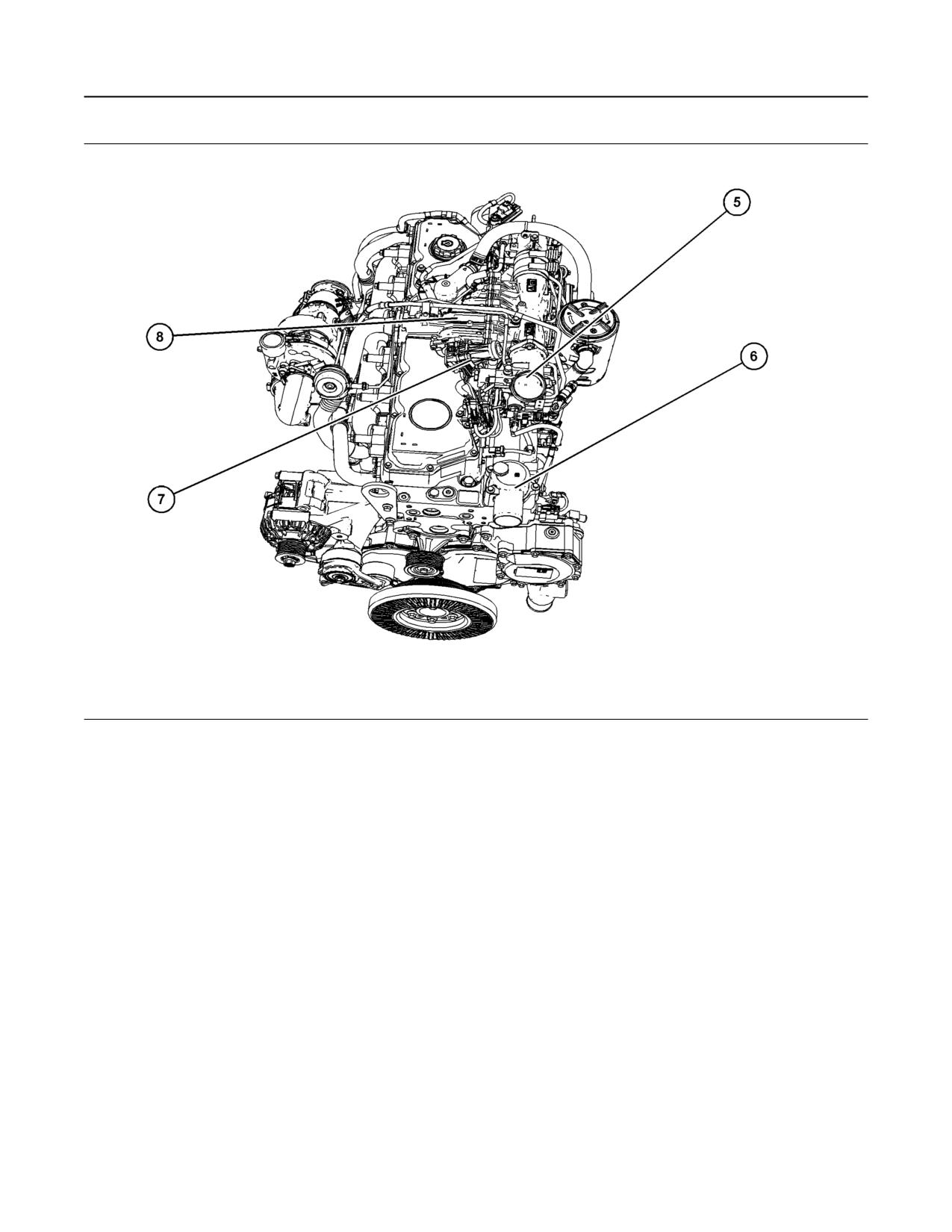
Illustration 23
g06236982
Typical example
(5) Air intake
(7) NOx Reduction System (NRS) Valve
(6) Coolant outlet
(8) NRS cooler
M0082024-03
29
Product Information Section
Model View Illustrations
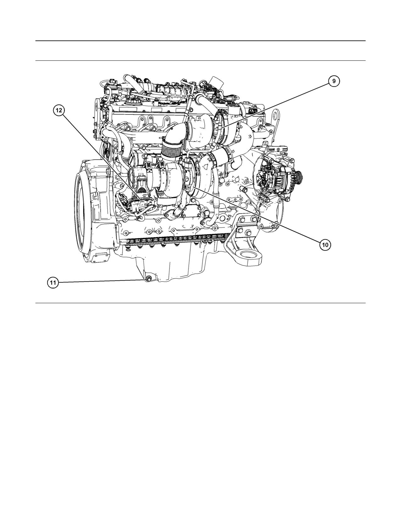
Illustration 24
g06237253
Typical example
(9) High-pressure turbocharger
(11) Oil drain plug
(10) Low-pressure turbocharger
(12) Back pressure valve
Aftertreatment Systems
There are two types of aftertreatment systems that
the 1206J engines could use. The type used will
depend on engine rating /power.
30
M0082024-03
Product Information Section
Model View Illustrations
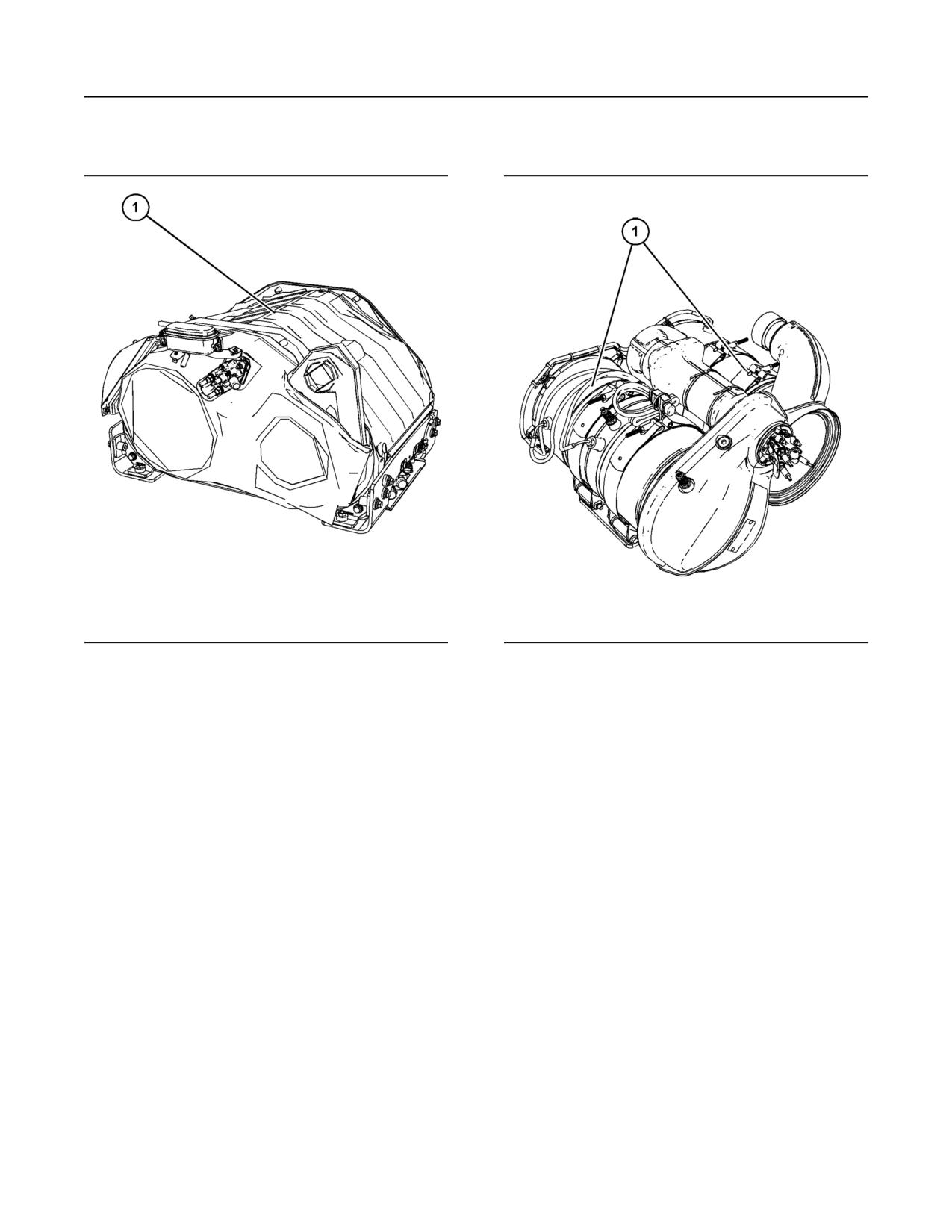
Enclosed Type Clean Emission Module
Open Type Clean Emission Module
Illustration 25
g06237255
Illustration 26
g06237257
Typical example
Typical example
(1) Enclosed clean emission module
(1) Open type clean emission module
The enclosed CEM contains three main parts the
Diesel Oxidation Catalyst (DOC) Diesel Exhaust
Filter (DPF) and the Selective Catalytic Reduction
(SCR). The Enclosed CEM also has a mixer
chamber.
M0082024-03
31
Product Information Section
Model View Illustrations
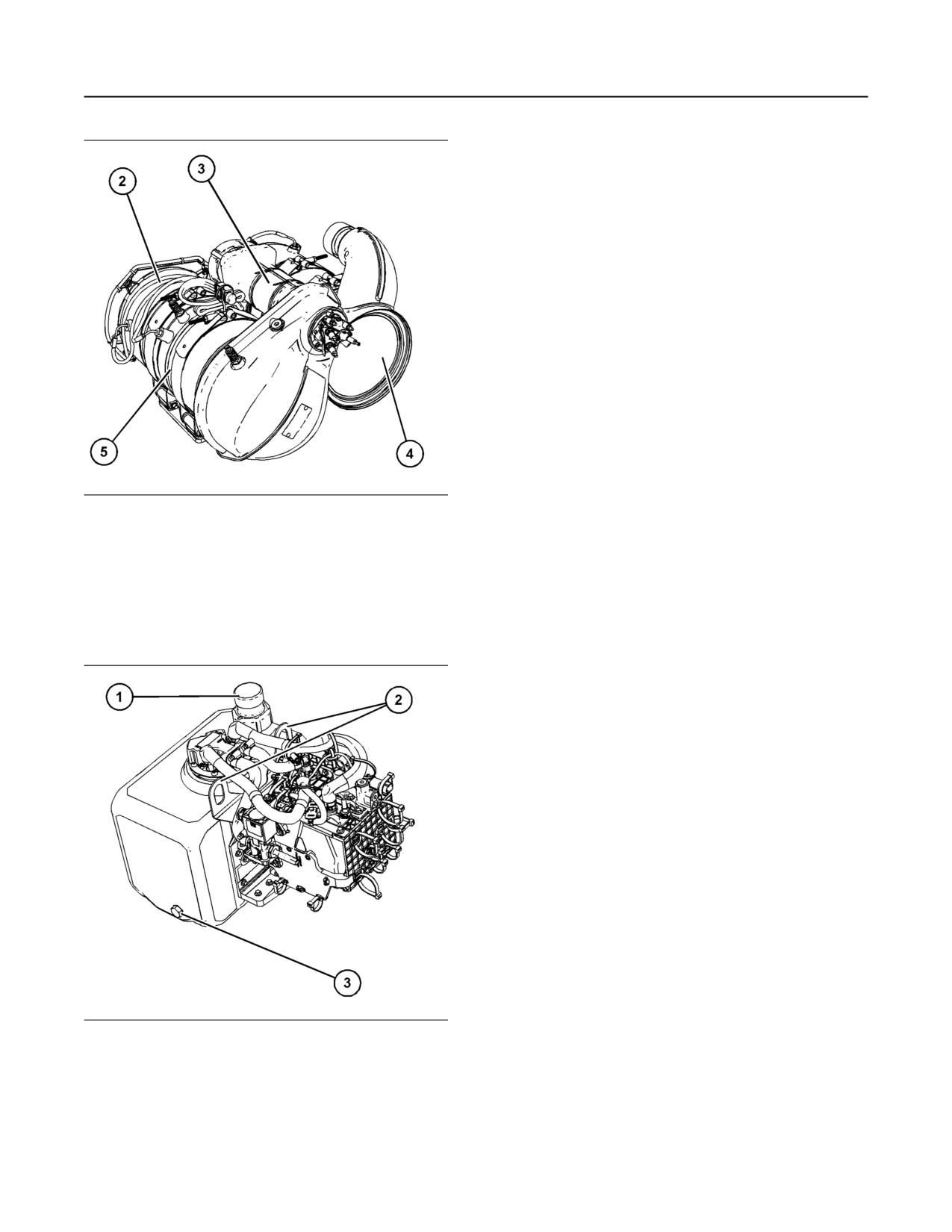
Illustration 27
g06238393
Typical example
(2) DOC
(3) Mixer
(4) SCR
(5) DPF
Pump Tank Unit (PTU)
Illustration 28
g06237309
Typical example
(1) DEF Filler cap
(2) PTU lifting eyes
(3) DEF tank drain plug
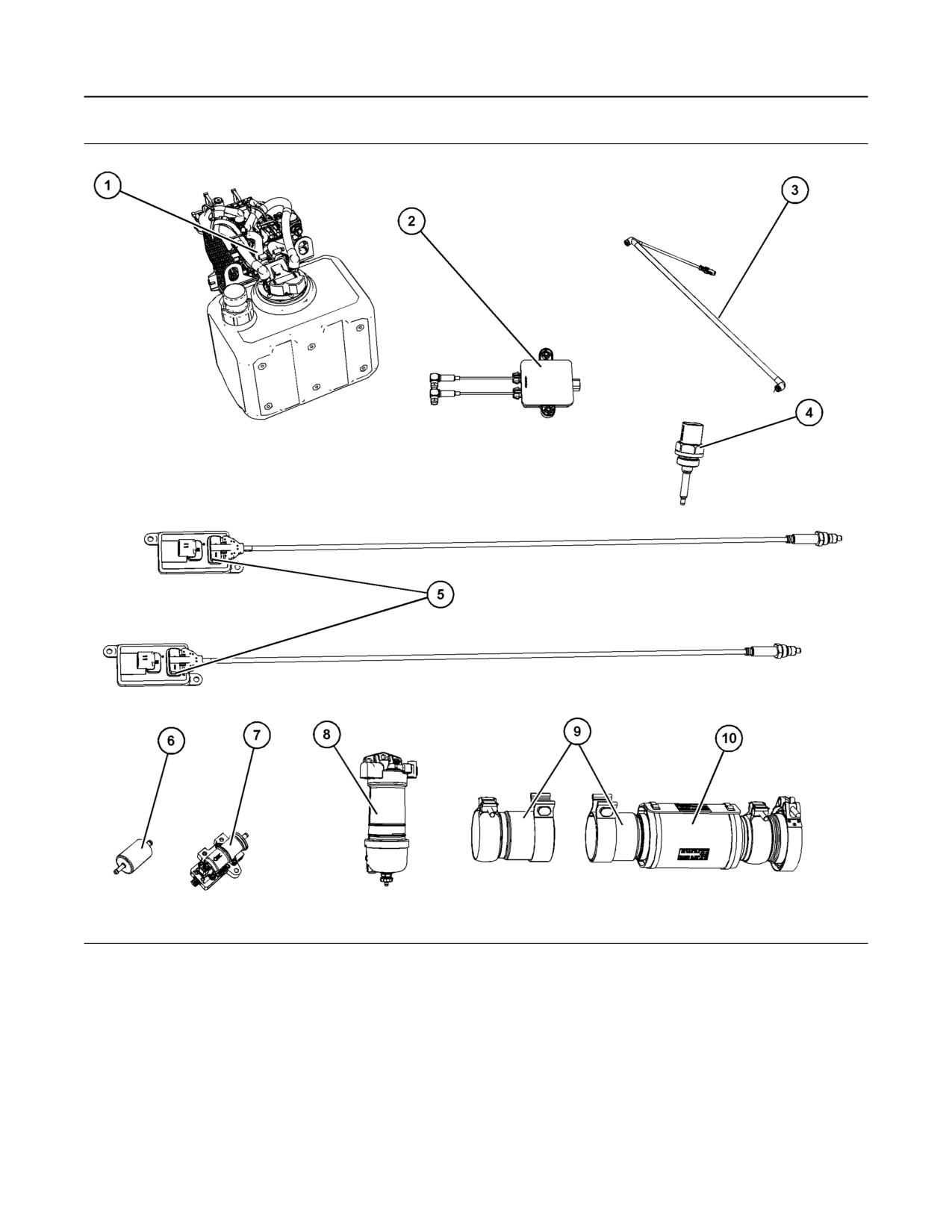
Off Engine Components
32
M0082024-03
Product Information Section
Model View Illustrations
Illustration 29
g06237277
Typical examples
(1) Diesel Exhaust Fluid (DEF) Pump tank
(4) Inlet air temperature sensor
(8) Primary fuel filter
unit
(5) NOx sensors
(9) Flexible exhaust pipe assembly
(2) Soot sensor control
(6) In-line fuel filter
(10) Protection sleeve for flexible exhaust
(3) DEF heated line
(7) Priming/transfer pump
pipe
M0082024-03
33
Product Information Section
Product Description
i07103827
Product Description
(Engine and Aftertreatment)
There are two variants of the Perkins 1206J industrial
engine, the 1206J-E70TA is a single turbocharged
engine and the engine prefix is VL.
The 1206J-E70TTA is a series turbocharged engine
and the prefix for this engine is VM.
The Perkins 1206J-E70TA and the 1206J-E70TTA
Industrial Engines have the following characteristics.
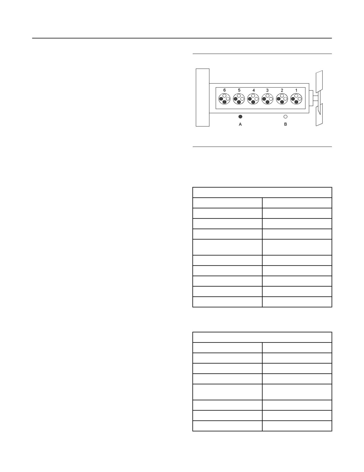
Illustration 30
g01127295
• In-line Six cylinder
Cylinder and valve location
(A) Exhaust valves
• Four stroke cycle
(B) Inlet valves
• Four valves in each cylinder
Table 1
• Series turbocharged charge cooled/or Single
1206J-E70TA Single Turbocharged Engine Specifications
turbocharged charge cooled
Operating Range (rpm)
900 to 2800(1)
• Aftertreatment System
Number of Cylinders
6 In-Line
There are different designs of aftertreatment that can
Bore
105 mm (4.13 inch)
be installed on the 1206J industrial engine. The
aftertreatment design will depend on engine rating/
Stroke
135 mm (5.31495 inch)
power. The Clean Emissions Module (CEM) is
Power
125 to 151 kW
constructed of four main items, the diesel oxidation
(167.62 to 202.5 hp)
catalyst, the Diesel Particulate Filter (DPF), the mixer
chamber, and the Selective Catalytic Reduction
Aspiration
Turbocharged charge cooled
(SCR).
Compression Ratio
16.5:1
The SCR requires the use of Diesel Exhaust Fluid
Displacement
7.01 L (428 in3)
(DEF) to be injected into the system to lower the
emissions from the engine. The DEF is injected into
Firing Order
1-5-3-6-2-4
the mixer chamber. The DEF tank can be installed
separate from the electronic pump unit
Rotation (flywheel end)
Counterclockwise
For more information on DEF, refer this Operation
(1) The operating rpm depends on the engine rating, the applica-
and Maintenance Manual, “Fluid Recommendations”.
tion, and the configuration of the throttle.
Table 2
Engine Specifications
1206J-E70TTA Series Turbocharged Engine Specifications
Note: The front end of the engine is opposite the
Operating Range (rpm)
900 to 2800(1)
flywheel end of the engine. The left and the right
sides of the engine are determined from the flywheel
Number of Cylinders
6 In-Line
end. The number 1 cylinder is the front cylinder.
Bore
105 mm (4.13 inch)
Stroke
135 mm (5.31495 inch)
Power
151 to 205 kW
(202.5 to 274.9 hp)
Aspiration
Turbocharged charge cooled
Compression Ratio
16.5:1
Displacement
7.01 L (428 in3)
(continued)
34
M0082024-03
Product Information Section
Engine and Aftertreatment
(Table 2, contd)
Most of the diagnostic codes are logged and stored in
the ECM. For additional information, refer to the
Firing Order
1-5-3-6-2-4
Operation and Maintenance Manual, “Engine
Rotation (flywheel end)
Counterclockwise
Diagnostics” topic (Operation Section).
(1) The operating rpm depends on the engine rating, the applica-
tion, and the configuration of the throttle.
Engine Cooling and Lubrication
The cooling system and lubrication system consists
Electronic Engine Features
of the following components:
The engine and aftertreatment operating conditions
• Gear-driven centrifugal water pump
are monitored. The Electronic Control Module (ECM)
controls the response of the engine to these
• Water temperature regulator which regulates the
conditions and to the demands of the operator. These
engine coolant temperature
conditions and operator demands determine the
precise control of fuel injection by the ECM. The
• Gear-driven gerotor type oil pump
electronic engine control system provides the
following features:
• Oil cooler
• Engine monitoring
The engine lubricating oil is supplied by a gerotor
type oil pump. The engine lubricating oil is cooled
• Engine speed governing
and the engine lubricating oil is filtered. The bypass
valve can provide unrestricted flow of lubrication oil to
• Control of the injection pressure
the engine if the oil filter element should become
plugged.
• Cold start strategy
Engine efficiency, efficiency of emission controls, and
• Automatic air/fuel ratio control
engine performance depend on adherence to proper
operation and maintenance recommendations.
• Torque rise shaping
Engine performance and efficiency also depend on
the use of recommended fuels, lubrication oils, and
• Injection timing control
coolants. Refer to this Operation and Maintenance
Manual, “Maintenance Interval Schedule” for more
• System diagnostics
information on maintenance items.
• NOx reduction system control
Engine Service Life
• Aftertreatment system control
Engine efficiency and maximum utilization of engine
performance depend on the adherence to proper
The ECM provides an electronic governor that
operation and maintenance recommendations. In
controls the injector output to maintain the desired
addition, use recommended fuels, coolants, and
engine speed.
lubricants. Use the Operation and Maintenance
Manual as a guide for required engine maintenance.
For more information on electronic engine features,
refer to the Operation and Maintenance Manual,
Expected engine life is generally predicted by the
“Features and Controls” topic (Operation Section).
average power that is demanded. The average
power that is demanded is based on fuel
Engine Diagnostics
consumption of the engine over time. Reduced hours
of operation at full throttle and/or operating at
The engine has built-in diagnostics to ensure that the
reduced throttle settings result in a lower average
engine systems are functioning correctly. The
power demand. Reduced hours of operation will
operator will be alerted to the condition by a “Stop or
increase the length of operating time before an
Warning” lamp. Under certain conditions, the engine
engine overhaul is required. For more information,
horsepower and the vehicle speed may be limited.
refer to the Operation and Maintenance Manual,
The electronic service tool may be used to display
“Overhaul Considerations” topic (Maintenance
the diagnostic codes.
Section).
There are three types of diagnostic codes: active,
Aftermarket Products and Perkins
logged, and event.
Engines
Perkins does not warrant the quality or performance
of non-Perkins fluids and filters.
M0082024-03
35
Product Information Section
Engine and Aftertreatment
When auxiliary devices, accessories, or
consumables (filters, additives, catalysts) made by
other manufacturers are used on Perkins products,
the Perkins warranty is not affected simply because
of such use.
However, failures that result from the installation
or use of other manufacturers devices,
accessories, or consumables are NOT Perkins
defects. Therefore, the defects are NOT covered
under the Perkins warranty.
Aftertreatment System
The aftertreatment system is approved for use by
Perkins. To be emissions-compliant only the
approved Perkins aftertreatment system must be
used on a Perkins engine.
36
M0082024-03
Product Information Section
Product Identification Information
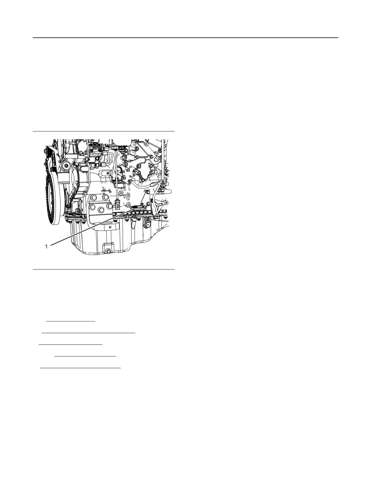
Serial Number Plate (1)
Product Identification
Information
The engine serial number plate is on the left side of
the cylinder block to the rear of the front engine
mounting.
i07103869
Plate Locations and Film
Locations
Illustration 31
g03046077
Perkins engines are identified by an engine serial
number.
An example of an engine number is
VL*****U000001C.
*****
The list number for the engine
VL
Type of engine
U
Built in the United Kingdom
000001
Engine Serial Number
W
Year of Manufacture
Perkins dealers or Perkins distributors need all these
numbers to determine the components that were
included with the engine. This information permits
accurate identification of replacement part numbers.
The numbers for fuel setting information for electronic
engines are stored within the flash file. These
numbers can be read by using the electronic service
tool.
M0082024-03
37
Product Information Section
Plate Locations and Film Locations
i07155370
Plate Locations and Film
Locations
(Aftertreatment System)
Clean Emissions Module (CEM)
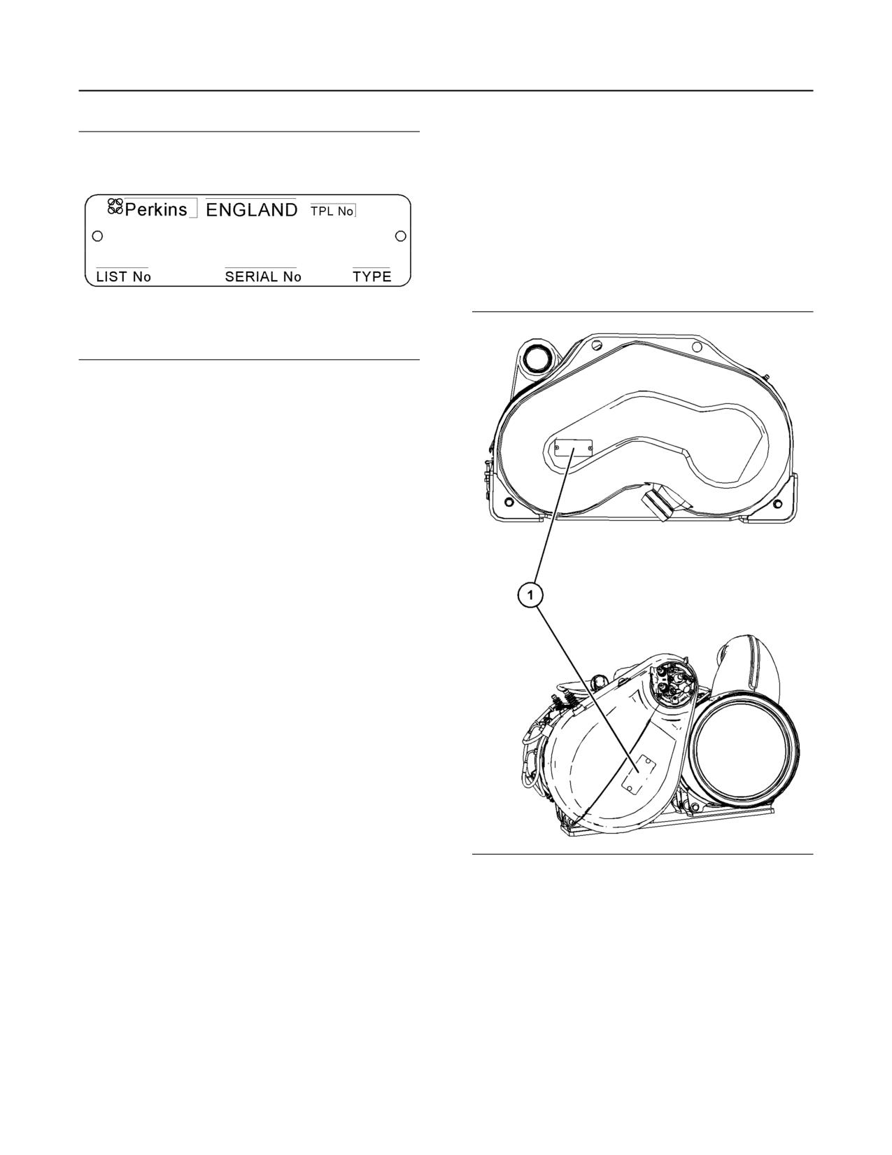
Illustration 32
g01094203
Serial number plate
Illustration 33
g06237359
Typical example
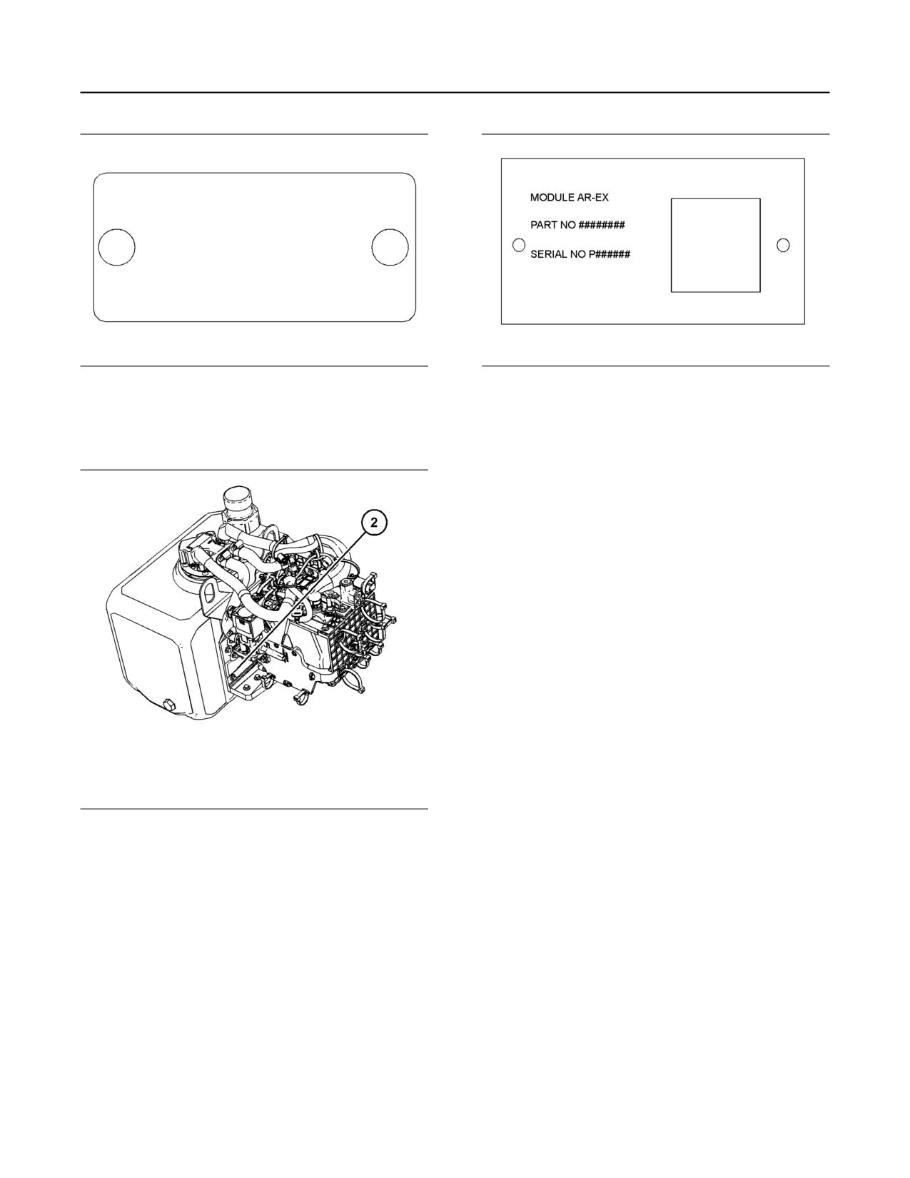
The identification plate (1) is on the end of the CEM.
38
M0082024-03
Product Information Section
Emissions Certification Film
Illustration 34
g06394552
Illustration 36
g03049116
Typical example of a CEM identification plate
Typical example of a PTU serial plate
Record the information on the CEM and PTU serial
Pump Tank Unit (PTU)
plates. The information will be required by your
Perkins dealer or your Perkins distributor to identify
replacement part numbers.
i07676597
Emissions Certification Film
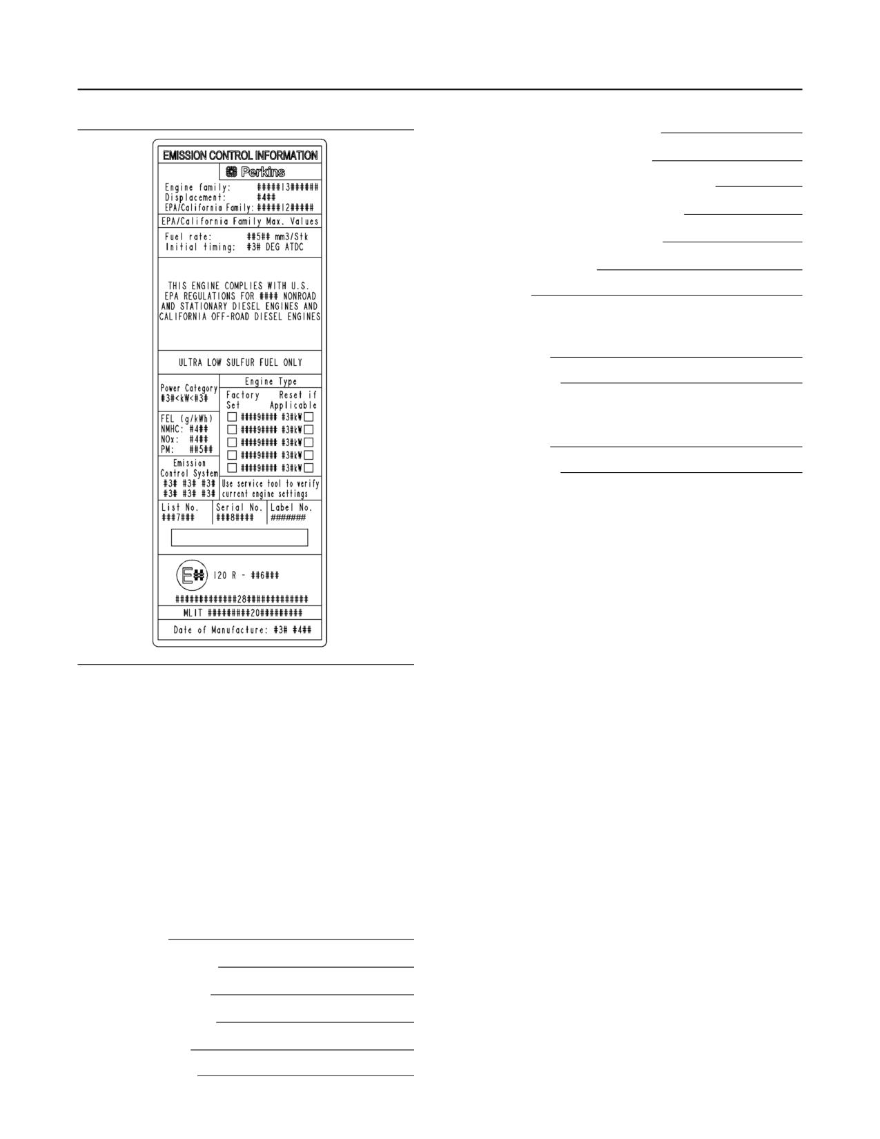
The label for the emissions is installed on the front
gear cover.
Note: A second emissions label will be supplied with
the engine. If necessary, the second emissions label
will be installed on the application by the original
equipment manufacturer.
Illustration 35
g06237396
Typical example
The location of the PTU serial plate (2).
M0082024-03
39
Product Information Section
Reference Information
Secondary Fuel Filter Element
Lubrication Oil Filter Element
Auxiliary Oil Filter Element (if equipped)
Total Lubrication System Capacity
Total Cooling System Capacity
Air Cleaner Element
Drive Belt
Clean Emissions Module
Part Number
Serial Number
Pump Tank Unit
Part Number
Serial Number
Illustration 37
g02443596
Typical example
i07155458
Reference Information
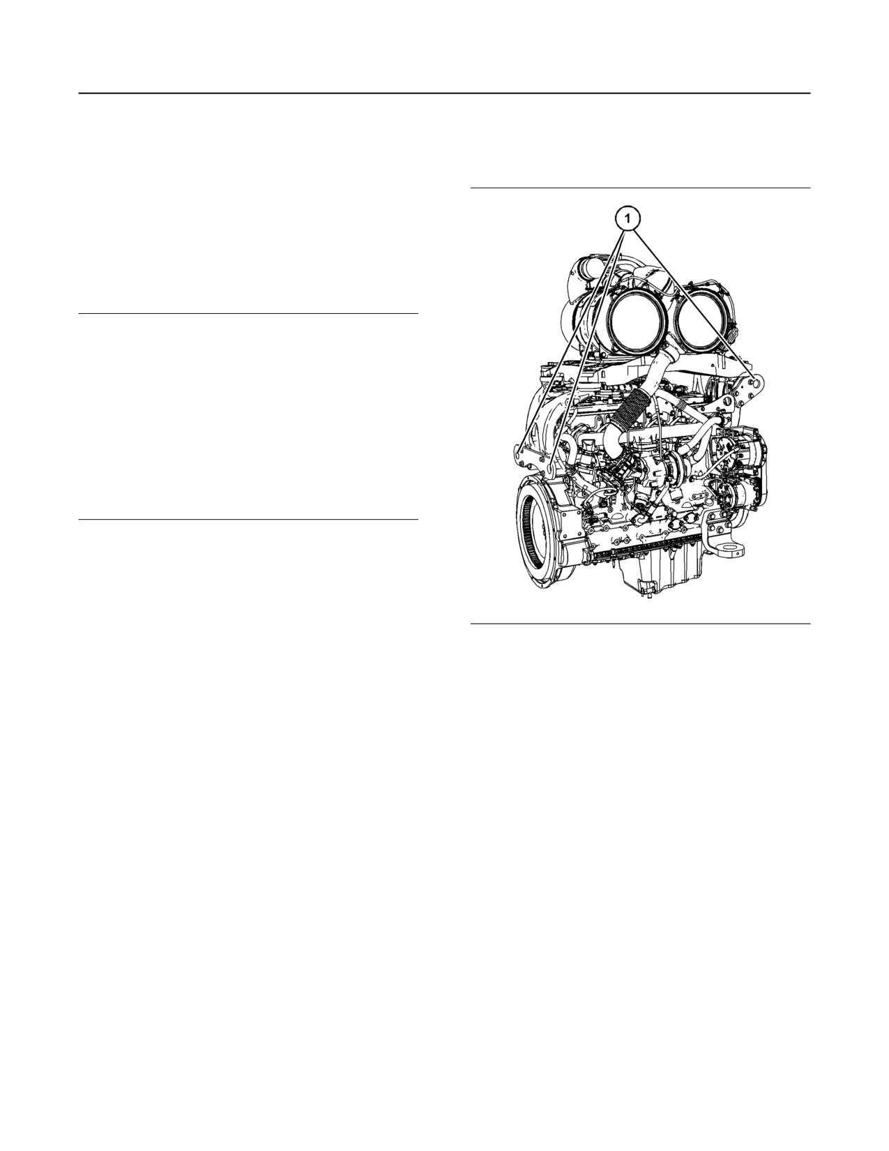
Information for the following items may be needed to
order parts. Locate the information for your engine.
Record the information in the appropriate space.
Make a copy of this list for a record. Keep the
information for future reference.
Record for Reference
Engine Model
Engine Serial number
Engine Low Idle rpm
Engine Full Load rpm
In Line Fuel Filter
Primary Fuel Filter
40
M0082024-03
Operation Section
Lifting and Storage
Operation Section
Engine and Clean Emissions
Module (CEM)
Lifting and Storage
i07103894
Product Lifting
NOTICE
Always inspect lifting eyebolts and all other lifting
equipment for damage before performing any lifting.
Never bend the eyebolts and the brackets. Never
perform product lifting if components are damaged.
Only load the eyebolts and the brackets under ten-
sion. Remember that the capacity of an eyebolt is re-
duced as the angle between the supporting members
and the object becomes less than 90 degrees.
When it is necessary to remove a component at an
angle, only use a link bracket that is properly rated for
the weight.
Read all the information within Product Lifting before
any lifting is attempted. Ensure that the correct set of
lifting eyes for the assembly to be lifted have been
selected.
Use a hoist to remove heavy components. Use an
adjustable lifting beam to lift the assembly. All
supporting members (chains and cables) should be
Illustration 38
g06393841
parallel to each other. The chains and cables should
Typical example
be perpendicular to the top of the object that is being
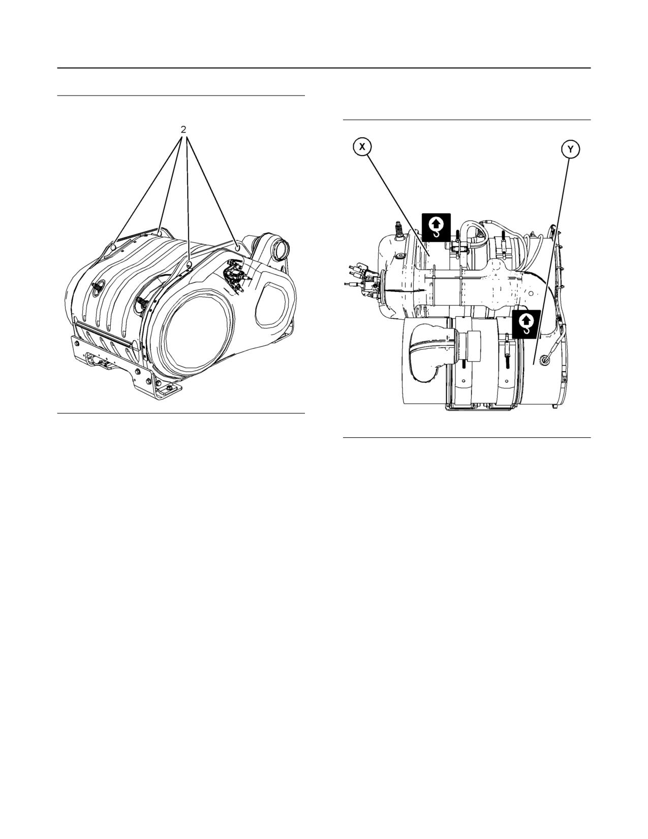
(1) Lifting eyes for engine and aftertreatment.
lifted.
Perkins recommends that model-specific cradles are
Refer to illustration38 for the location of the lifting
eyes.
used to store and transport engines. Supporting
engines on the sump/oil pan is not recommended
under any circumstances. This action is for both
Enclosed CEM
safety and quality reasons.
Ensure that the exhaust inlet for the CEM is not
damaged during removal and installation. Do not
allow the weight of the CEM to act on the exhaust
inlet.
M0082024-03
41
Operation Section
Product Lifting
Open CEM
Illustration 39
g03051677
Typical example
Illustration 40
g06239792
(2) Lifting eyes for the CEM
Typical example
Refer to illustration 39 for the location of the lifting
eyes to lift the CEM. The lifting eyes (2) are designed
Install a suitable sling in position (X) and install a
only to lift the CEM. The lifting eyes (2) must not be
suitable sling in position (Y). Ensure that the slings
used to lift any other parts of the application.
only contact the body of the CEM. A test lift may be
required to achieve the correct balance of the
Note: If the CEM is removed from the application, the
assembly. The weight of the CEM is approximately
inlet and outlet connections must be protected to
64.5 kg (142.2 lb).
prevent damage and dirt ingress.
Pump Tank Unit (PTU) Only
The tank on the PTU should be empty before the
assembly is lifted.
42
M0082024-03
Operation Section
Product Lifting
Engine Only
Illustration 41
g03419909
Typical example
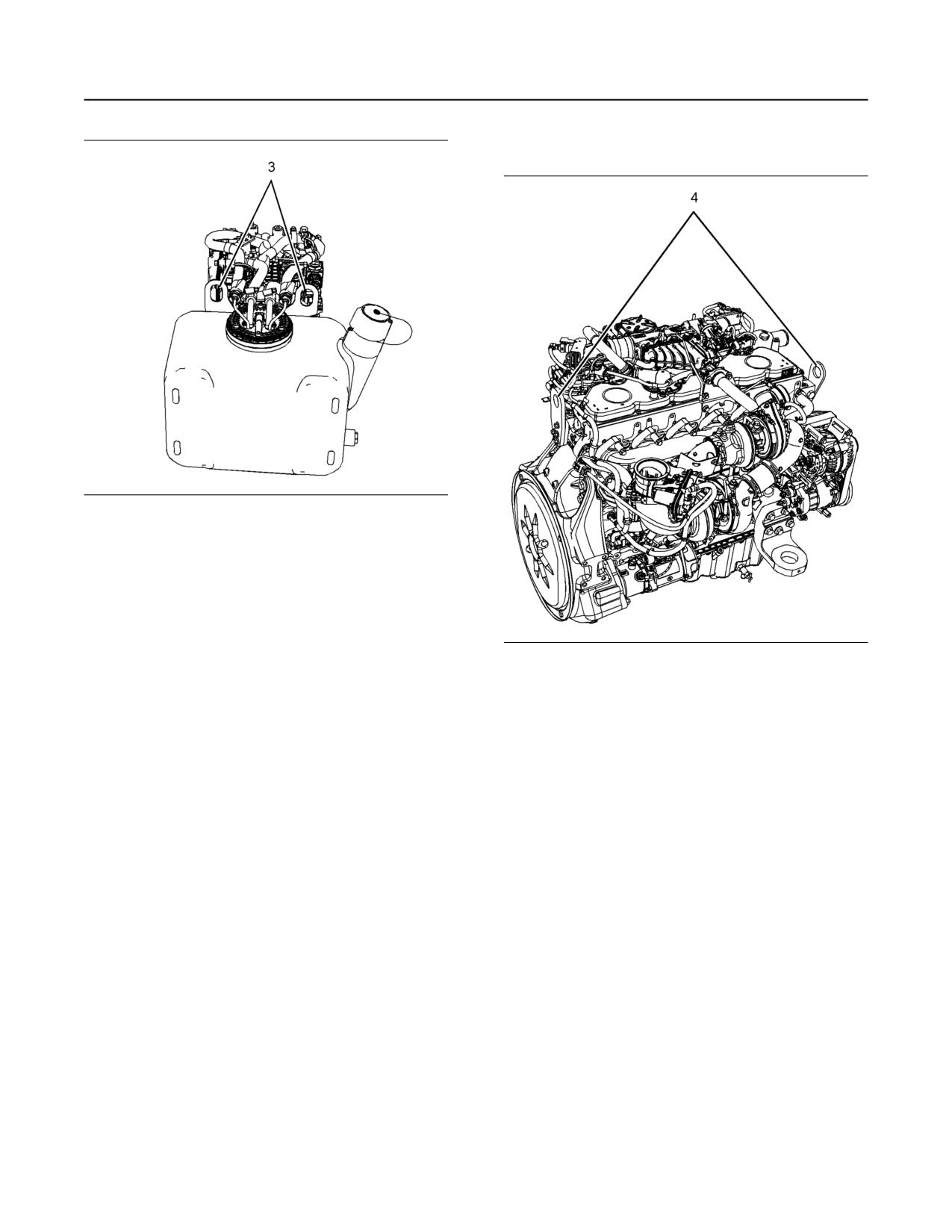
(3) Lifting eyes for PTU and DEF tank.
Refer to illustration 41 for the location of the lifting
eyes to lift the PTU and DEF tank.
Illustration 42
g03051679
Typical example
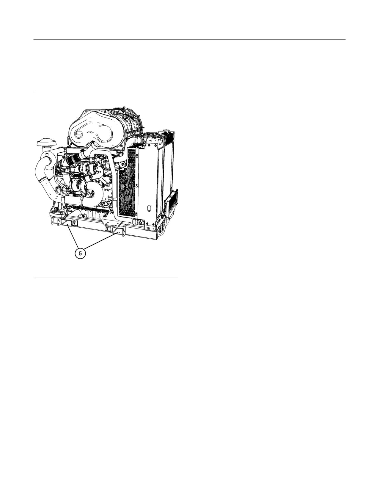
(4) Lifting eyes for the engine
M0082024-03
43
Operation Section
Product Storage
Refer to illustration 41 for the location of the lifting
Allow at least 2 minutes after the engine has stopped
eyes to lift the engine.
before you turn the battery disconnect switch to OFF.
Disconnecting the battery power too soon will prevent
purging of the DEF fluid lines after the engine is shut
Engine CEM and Radiator
down. Also, during the 2 minutes the engine
electronic control module is active storing information
from the engine and aftertreatment sensors.
Condition for Storage
The engine must be stored in a water proof building.
The building must be kept at a constant temperature.
Engines that are filled with Perkins ELC will have
coolant protection to an ambient temperature of
-36° C (-32.8° F). The engine must not be subjected
to extreme variations in temperature or humidity.
Storage Period
An engine can be stored for up to 6 months provided
all the recommendations are adhered to.
Storage Procedure
Keep a record of the procedure that has been
completed on the engine.
Note: Do not store an engine that has biodiesel in the
fuel system.
1. Ensure that the engine is clean and dry.
a. If the engine has been operated using
biodiesel, the system must be drained and new
Illustration 43
g06157681
filters installed. The fuel tank will require
flushing.
(5) Lifting location
b. Fill the fuel system with an ultra low sulfur fuel.
The engine CEM and radiator are mounted on a
For more information on acceptable fuels refer
frame. This entire package can only be lifted using
suitable fork lift tines. Refer to illustration 43 for the
to this Operation and Maintenance Manual,
fork lift tine locations.
“Fluid Recommendations”. Operate the engine
for 15 minutes to remove all biodiesel from the
i07682728
system.
Product Storage
2. Drain any water from the primary filter water
separator. Ensure that the fuel tank is full.
(Engine and Aftertreatment)
3. The engine oil will not need to be drained to store
the engine. Provided the correct specification of
Perkins are not responsible for damage which may
engine oil is used the engine can be stored for up
occur when an engine is in storage after a period in
to 6 months. For the correct specification of engine
service.
oil refer to this Operation and Maintenance
Manual, “Fluid Recommendations”.
Your Perkins dealer or your Perkins distributor can
help with preparing the engine for extended storage
4. Remove the drive belt from the engine.
periods.
Sealed Coolant System
Ensure that the cooling system is filled with the
correct specification of coolant. Refer to this
Operation and Maintenance Manual, “Fluid
Recommendations”.
44
M0082024-03
Operation Section
Engine and Aftertreatment
Open Cooling System
1. If necessary, drain the tank and fill with DEF that
meets ISO 22241-1.
Ensure that all coolant drain plugs have been
opened. Allow the coolant to drain. Install the drain
2. Replace the DEF filter, refer to this Operation and
plugs. Place a vapor phase inhibitor into the system.
Maintenance Manual, “Diesel Exhaust Fluid Filter-
The coolant system must be sealed once the vapor
Clean/Replace”.
phase inhibitor has been introduced. The effect of the
vapor phase inhibitor will be lost if the cooling system
3. Ensure that the drive belt is correctly installed.
is open to the atmosphere.
Ensure that all engine coolant and engine oil has
the correct specification and grade. Ensure that
For maintenance procedures refer to this Operation
the coolant and the engine oil are at the correct
and Maintenance Manual.
level. Start the engine. If a fault becomes active
turn off the engine, allow 2 minutes for the DEF
Monthly Checks
system to purge, then restart the engine.
The crankshaft must be rotated to change the spring
4. If the fault remains active, refer to Troubleshooting
loading on the valve train. Rotate the crankshaft
for more information.
more than 180 degrees. Visibly check for damage or
corrosion to the engine and aftertreatment.
Table 3
Temperature
Duration
Ensure that the engine and aftertreatment are
covered completely before storage. Log the
10° C (50° F)
36 months
procedure in the record for the engine.
25° C (77° F)
18 months
Aftertreatment
30° C (86° F)
12 months
35° C (95° F)(1)
6 months
The engine must be allowed to perform a Diesel
Exhaust Fluid (DEF) purge before the battery
(1) At 35° C, significant degradation can occur. Check every batch
disconnect switch is turned off. Allow 2 minutes after
before use.
the engine has stopped before using the battery
disconnect switch.
The exhaust outlet of the aftertreatment must be
capped. To prevent damage to the exhaust outlet
connection during storage, the weight of the CEM
must not act on the exhaust outlet.
DEF Tank Storage
1. Ensure normal engine shutdown, allow the DEF to
be purged. Do not disconnect the battery
disconnect switch, allow 2 minutes after key off
before disconnection.
2. Fill the tank with DEF that meets all the
requirement defined in ISO 22241-1.
3. Ensure that all DEF lines and electrical
connections are reconnected prior to storage, to
prevent DEF crystals from forming.
4. Ensure that the DEF filler cap is correctly installed.
Removal from Storage
DEF has a limited life, refer to table 3 for the time and
temperature range. DEF that is outside this range
MUST be replaced.
On removal from storage the DEF quality in the tank
must be tested with a refractometer. The DEF in the
tank must meet the requirements defined in ISO
22241-1 and comply with table 3 .
M0082024-03
45
Operation Section
Features and Controls
Intake manifold pressure - The intake manifold
Features and Controls
pressure sensor checks the rated pressure in the
engine manifold.
i07277418
Fuel rail pressure - The fuel rail pressure sensor
measures the high pressure or low pressure in the
Alarms and Shutoffs
fuel rail. The ECM will check the pressure.
Engine oil pressure - The engine oil pressure
sensor indicates when oil pressure drops below rated
Shutoffs
system pressure, at a set engine speed.
The shutoffs are electrically operated or mechanically
Engine overspeed - If the engine rpm exceeds the
operated. The electrically operated shutoffs are
overspeed setting, the alarm will be activated.
controlled by the ECM.
Air filter restriction - The switch checks that the air
Shutoffs are set at critical levels for the following
filter is not clogged/blocked when the engine is
items:
operating.
User-defined switch - This switch can shut down
• Operating temperature
the engine remotely.
• Operating pressure
Water in fuel switch - This switch checks for excess
water in the primary fuel filter when the engine is
• Operating level
operating.
• Operating rpm
Fuel temperature - The fuel temperature sensor
monitors the pressurized fuel in the high-pressure
The particular shutoff may need to be reset before
fuel pump.
the engine will start.
NOTICE
Note: The sensing element of the coolant
Always determine the cause of the engine shutdown.
temperature switch/sensor must be submerged in
Make necessary repairs before attempting to restart
coolant to operate.
the engine.
Engines may be equipped with alarms to alert the
operator when undesirable operating conditions
Be familiar with the following items:
occur.
• Types and locations of shutoff
NOTICE
When an alarm is activated, corrective measures
• Conditions which cause each shutoff to function
must be taken before the situation becomes an emer-
gency in order to avoid possible engine damage.
• The resetting procedure that is required to restart
the engine
If corrective measures are not taken within a
reasonable time, engine damage could result. The
Alarms
alarm will continue until the condition is corrected.
The alarm may need to be reset.
The alarms are electrically operated. The operations
of the alarms are controlled by the ECM.
Note: If installed, the coolant level switch and the oil
level switch are indicators. Both switches operate
The alarm is operated by a sensor or by a switch.
when the application is on level ground and the
When the sensor or the switch is activated, a signal is
engine RPM at zero.
sent to the ECM. An event code is created by the
ECM. The ECM will send a signal to illuminate the
Clean Emissions Module (CEM)
lamp.
Your engine may be equipped with the following
• Diesel Oxidation Catalyst
(DOC)
sensors or switches:
• Selective Catalyst Reduction
(SCR)
Coolant temperature - The coolant temperature
sensor indicates high jacket water coolant
Soot Sensors - The soot sensors monitor the soot
temperature.
level within the CEM
Intake manifold air temperature - The intake
NOx Sensors - Two NOx sensors monitor the NOx
concentration within the exhaust gas before and after
manifold air temperature sensor indicates high intake
the selective catalyst reduction module.
air temperature.
46
M0082024-03
Operation Section
Battery Disconnect Switch
Temperature Sensors - A temperature sensor after
the engine exhaust gas exit, after the DOC and
before the SCR module monitor the temperatures
within the system.
Pump Tank Unit (PTU) Alarms and
Shutoff
Diesel Exhaust Fluid (DEF) Level Sensor - The
DEF level sensor monitors the volume of fluid in the
tank and sends a signal to the ECM if the level drops
below a given point.
DEF Quality Sensor - The DEF quality sensor
checks the quality of the DEF within the tank and will
send the signal to the ECM if the DEF becomes
Illustration 44
g03265058
contaminated.
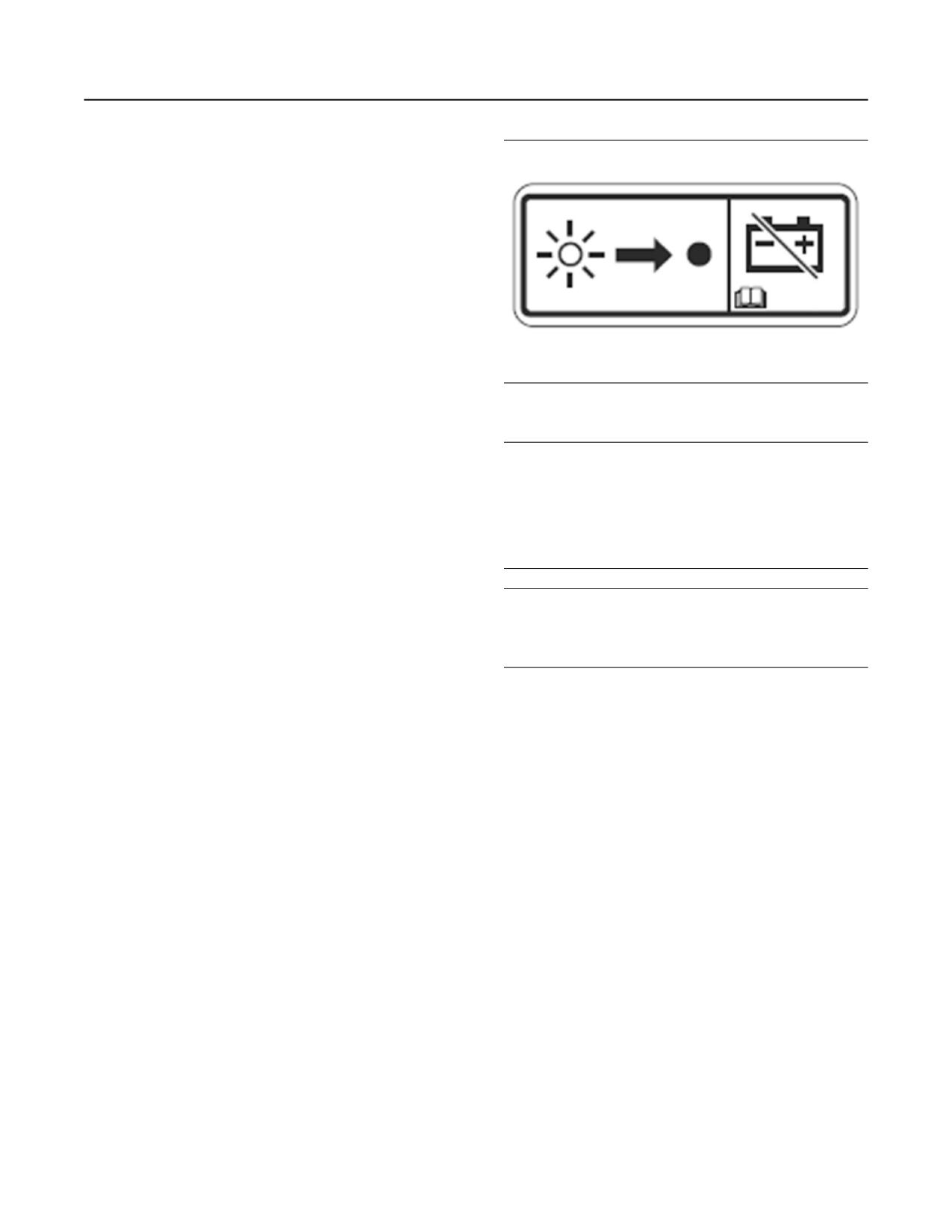
Battery disconnect switch label
NOTICE
Testing
Do not turn off the battery disconnect switch until the
indicator lamp has turned off. If the switch is turned
Turning the keyswitch to the ON position will check
off when the indicator lamp is illuminated the Diesel
the indicator lights on the control panel. All the
Exhaust Fluid (DEF) system will not purge the DEF. If
indicator lights will be illuminated for 2 seconds after
the DEF does not purge, DEF could freeze and dam-
the keyswitch is operated. Replace any bulbs that fail
age the pump and lines.
to light immediately.
Refer to Troubleshooting for more information.
NOTICE
Never move the battery disconnect switch to the OFF
i05408886
position while the engine is operating. Serious dam-
age to the electrical system could result.
Battery Disconnect Switch
(If Equipped)
i07671662
Gauges and Indicators
Allow at least 2 minutes after the engine has stopped
before you turn the battery disconnect switch to OFF.
Disconnecting the battery power too soon will prevent
Your engine may not have the same gauges or all of
purging of the Diesel Exhaust Fluid (DEF) lines after
the gauges that are described. For more information
the engine is shut down. Also, during the 2 minutes
about the gauge package, see the OEM information.
the engine Electronic Control Module (ECM) is active
storing information from the engine and
Gauges provide indications of engine performance.
aftertreatment sensors.
Ensure that the gauges are in good working order.
Not allowing the DEF purge to be performed can
Determine the normal operating range by observing
damage the DEF system. Not allowing the engine
the gauges over a period.
ECM time to store the information from the sensors
can damage to emission control system.
Noticeable changes in gauge readings indicate
potential gauge or engine problems. Problems may
Some applications, the engine can be equipped with
also be indicated by gauge readings that change
a wait to disconnect lamp. The wait to disconnect
even if the readings are within specifications.
lamp will be illuminated during engine operation and
Determine and correct the cause of any significant
will be extinguished approximately 2 minutes after
change in the readings. Consult your Perkins dealer
the engine has stopped.
or your Perkins distributor for assistance.
Some engine applications are equipped with
Indicator Lamps. Indicator lamps can be used as a
diagnostic aid. There are two lamps. One lamp has
an orange lens and the other lamp has a red lens.
These indicator lamps can be used in two ways:

M0082024-03
47
Operation Section
Gauges and Indicators
• The indicator lamps can be used to identify the
Tachometer - This gauge indicates
current operational status of the engine. The
engine speed (rpm). When the throttle
indicator lamps can also indicate that the engine
control lever is moved to the full throttle
has a fault. This system is automatically operated
position without load, the engine is running at
via the ignition switch.
high idle. The engine is running at the full load
rpm when the throttle control lever is at the full
• The indicator lamps can be used to identify active
throttle position with maximum rated load.
diagnostic codes. This system is activated by
pressing the Flash Code button.
NOTICE
To help prevent engine damage, never exceed the
Refer to the Troubleshooting Guide, “Indicator
high idle rpm. Overspeeding can result in serious
Lamps” for further information.
damage to the engine. Operation at speeds exceed-
ing high idle rpm should be kept to a minimum.
NOTICE
If no oil pressure is indicated, STOP the engine. If
maximum coolant temperature is exceeded, STOP
Ammeter - This gauge indicates the
the engine. Engine damage can result.
amount of charge or discharge in the
battery charging circuit. Operation of
the indicator should be to the “+” side of “0”
Engine Oil Pressure - The oil pressure
(zero).
should be greatest after a cold engine is
started. The typical engine oil pressure
Fuel Level - This gauge indicates the
with SAE10W40 is 350 to 450 kPa (50 to 65 psi) at
fuel level in the fuel tank. The fuel level
rated rpm.
gauge operates when the “START/STOP”
switch is in the “on” position.
A lower oil pressure is normal at low idle. If the
engine speed and load are stable and the gauge
Service Hour Meter - The gauge
reading changes, perform the following procedure:
indicates total operating hours of the
1. Remove the load.
engine.
2. Stop the engine.
Indicator Lamps
3. Check and maintain the oil level.
• Shutdown lamp
Jacket Water Coolant Temperature -
Typical temperature range is 82° to 94°C
• Warning lamp
(179.6° to 169.2°F). This temperature
range will vary according to engine load and the
• Low oil pressure lamp
ambient temperature.
• Wait to start lamp (Glow plug warning lamp)
A 100 kPa (14.5 psi) radiator cap must be installed
on the cooling system. The maximum temperature for
For information, refer to this manual, “Monitoring
the cooling system is 108° C (226.4° F). This
System (Table for the Indicator Lamps)” for the
sequence of operation of the shutdown lamp and the
temperature is measured at the outlet for the water
temperature regulator. The engine coolant
warning lamp.
temperature is monitored by the engine sensors and
The function of the wait to start lamp is automatically
the engine ECM. This programming cannot be
controlled at engine start-up.
altered. Derates can occur if the maximum engine
coolant temperature is exceeded.
The function of the low oil pressure lamp is controlled
by the engine ECM. If low oil pressure is detected,
If the engine is operating above the normal range,
the lamp will be illuminated. The reason for the
reduce the engine load. If high coolant temperatures
illumination of the low-pressure lamp should be
are a frequent event, perform the following
investigated immediately.
procedures:
1. Reduce the load on the engine.
The glow plug warning lamp will flash to show that
the engine is being held at low speed. This function
2. Determine if the engine must be shut down
will be performed at engine starting and the duration
immediately or if the engine can be cooled by
will depend on ambient temperature and engine
temperature.
reducing the load.
3. Inspect the cooling system for leaks. If necessary,
consult your Perkins dealer or your Perkins
distributor for assistance.
48
M0082024-03
Operation Section
Monitoring System
The lamps will illuminate for 2 seconds to check that
the lamps are functioning when the keyswitch is
turned to the ON position. If any of the lamps stay
illuminated, or a lamp fails to be illuminated the
reason should be investigated immediately.
Aftertreatment Lamps and gauges
All applications will require the following lamps and
gauges:
• Emission malfunction lamp
• Action indicator lamp
• Gauge for Diesel Exhaust Fluid (DEF)
• Low warning lamp for DEF
• Wait to disconnect lamp (optional)
The wait to disconnect lamp will be illuminated during
engine operation and will be extinguished
approximately 2 minutes after the engine has
stopped. Do not disconnect the battery disconnect
switch during the period the lamp is illuminated. The
diesel exhaust fluid system will be purged during this
time. Also, during the 2 minutes the engine electronic
control module is active storing information from the
engine and aftertreatment sensors.
Note: The wait to disconnect lamp will not be
checked at key on.
i07622830
Monitoring System
(Engine Indicators and
Aftertreatment Indicators)
Engine Indicator Lamps
Note: When in operation the amber warning lamp
has three states, solid, flashing, and fast flashing.
The sequence is to give a visual indication of the
importance of the warning. Some application can
have an audible warning installed.
Ensure that the engine maintenance is carried out at
the correct intervals. A lack of maintenance can
result in illumination of the warning lamp. For the
correct intervals of maintenance, refer to the
Operation and Maintenance Manual, “Maintenance
Interval Schedule”.

M0082024-03
49
Operation Section
Overspeed
Table 4
Indicator Lamp Table
Shutdown
Warning
Action Indi-
Lamp
cator Lamp
Lamp State
Description of the Indication
Engine Status
On
On
Lamp Check
When the keyswitch is moved to the ON po-
The keyswitch is in the ON position but the en-
sition, the lamps come on for 2 seconds and
gine has not yet been cranked.
the lamps will then go off.
If any of the indicators will not illuminate during indicator check, the fault must be investigated immediately
If any Indicators stay illuminated or flash, the fault must be investigated immediately.
Off
Off
No Faults
With the engine in operation, there are no
The engine is operating with no detected
active warnings, diagnostic codes, or event
faults.
codes.
On Solid
Off
Warning
Level 1 warning
The engine is operating normally but there is
one or more faults with the electronic manage-
ment system for the engine.
As soon as possible the fault should be investigated.
Flashing
Off
Warning
Level 2 warning
The engine continues to be operated, but the
level of importance of the warning has
increased.
Depending on the particular fault and the se-
verity the engine may be de-rated.
The engine could be damaged if continued to
be operated.
Stop the engine. Investigate the code.
Flashing
On
Engine Shutdown
Level 3 warning
The engine is either shutdown or an engine
If both the warning lamp and the shutdown
shutdown is imminent. One or more monitored
lamp are in operation, this issue indicates
engine parameters have exceeded the limit for
one of the following conditions.
an engine shutdown. This pattern of lamps can
be caused by the detection of a serious active
1. One or more of the shutdown values for
diagnostic code.
the engine protection strategy has been
exceeded.
Contact your Perkins dealer or your Perkins
distributor.
2. A serious active diagnostic code has
been detected.
If installed, the audible warning will sound.
After a short time period, the engine may
shut down.
Flash Codes
For more information on the illumination of the
aftertreatment indicators refer to this Operation and
Some applications may support flash codes. A flash
Maintenance Manual, “Selective Catalytic Reduction
code can be viewed by an indicator lamp that when
Warning System”.
asked will flash in a particular sequence. The
indicator lamp used to view the codes is the warning
i03554501
lamp, the lamp can then be referred to as a
diagnostic lamp. For more information refer to this
Overspeed
Operation and Maintenance Manual, “Diagnostic
Lamp”.
Aftertreatment System
• ECM
Electronic Control Module
• RPM
Revolutions Per Minute
The aftertreatment indicators should illuminate at key
on for 2 seconds to test the system. If any of the
An overspeed is detected by the speed/timing
indicators do not illuminate, the fault must be
sensors.
investigated immediately.
50
M0082024-03
Operation Section
Sensors and Electrical Components
The default setting for an overspeed is 3000 rpm.
The ECM will cut the power to the electronic unit
injectors, until the rpm drops below 200 rpm of the
overspeed setting. A diagnostic fault code will be
logged into the ECM memory and a warning lamp will
indicate a diagnostic fault code.
An overspeed can be set from 2600 rpm to 3000 rpm.
This setting depends on the application.
i07103912
Sensors and Electrical
Components
The illustrations within the following sections are
typical location of the sensors and electrical
components for an industrial engine. Specific
engines may appear different due to differences in
applications.
M0082024-03
51
Operation Section
Sensors and Electrical Components
Engine Components
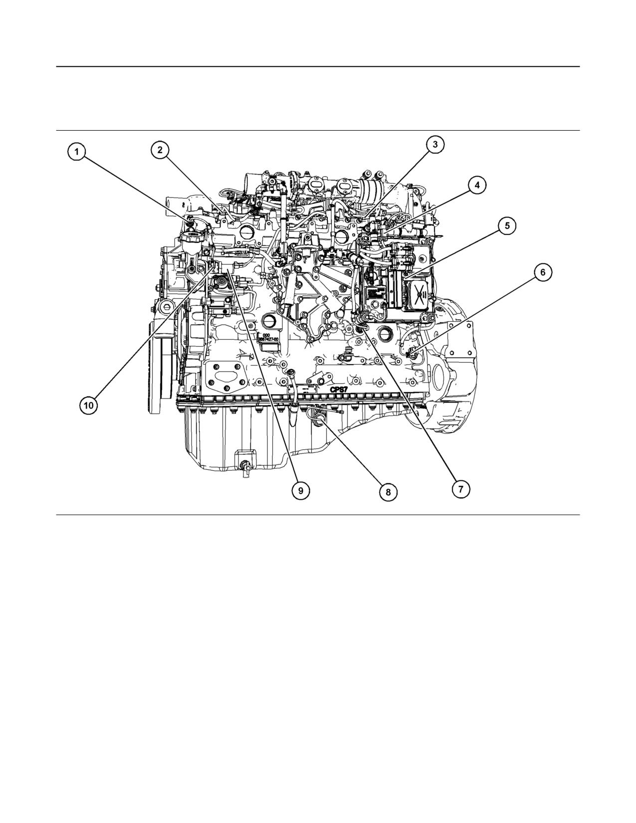
Illustration 45
g06237689
Typical example
(1) Coolant temperature sensor
(5) Electronic control module
(9) Solenoid for high-pressure fuel pump
(2) Injector harness connection
(6) Primary speed/timing sensor
(10) Fuel temperature sensor
(3) Injector harness connection
(7) Oil pressure sensor
(4) Diagnostic connector
(8) Oil level switch (if equipped)
52
M0082024-03
Operation Section
Sensors and Electrical Components
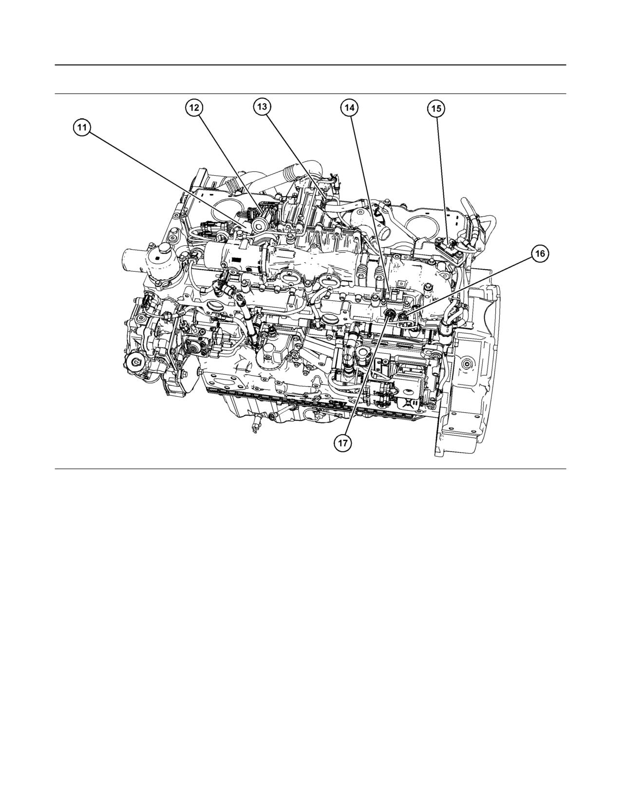
Illustration 46
g06237690
Typical example
(11) Wastegate regulator solenoid
(13) Temperature sensor for the NRS
(16) Manifold inlet pressure sensor
(12) Control valve for the NOx Reduction
(14) Fuel pressure sensor
(17) Manifold inlet temperature
System (NRS)
(15) NRS Differential pressure sensor
M0082024-03
53
Operation Section
Sensors and Electrical Components
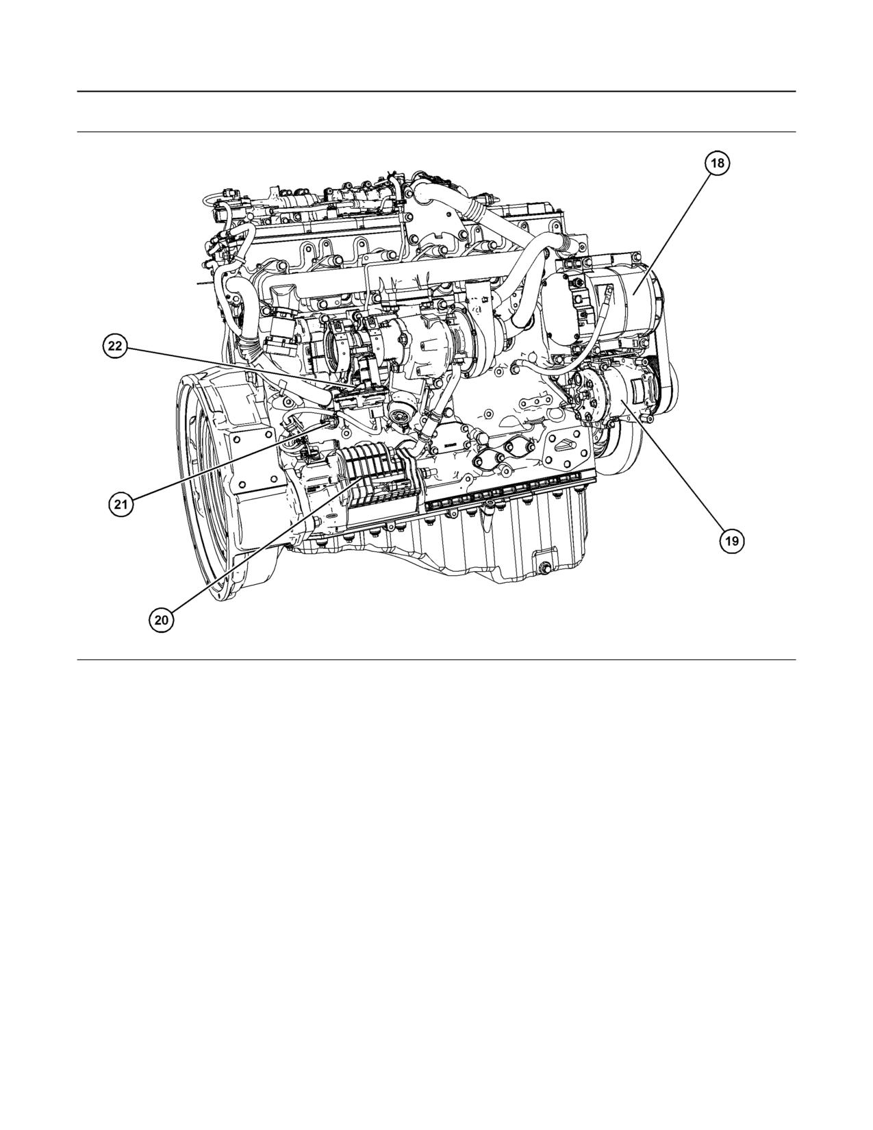
Illustration 47
g06237692
Typical example
(18) Alternator
(20) Starting motor
(22) Back pressure valve
(19) Refrigerant compressor
(21) Secondary speed/timing sensor