Parker Variable Speed Drive AC30 series. User’s Manual (2017) - page 36
F-21
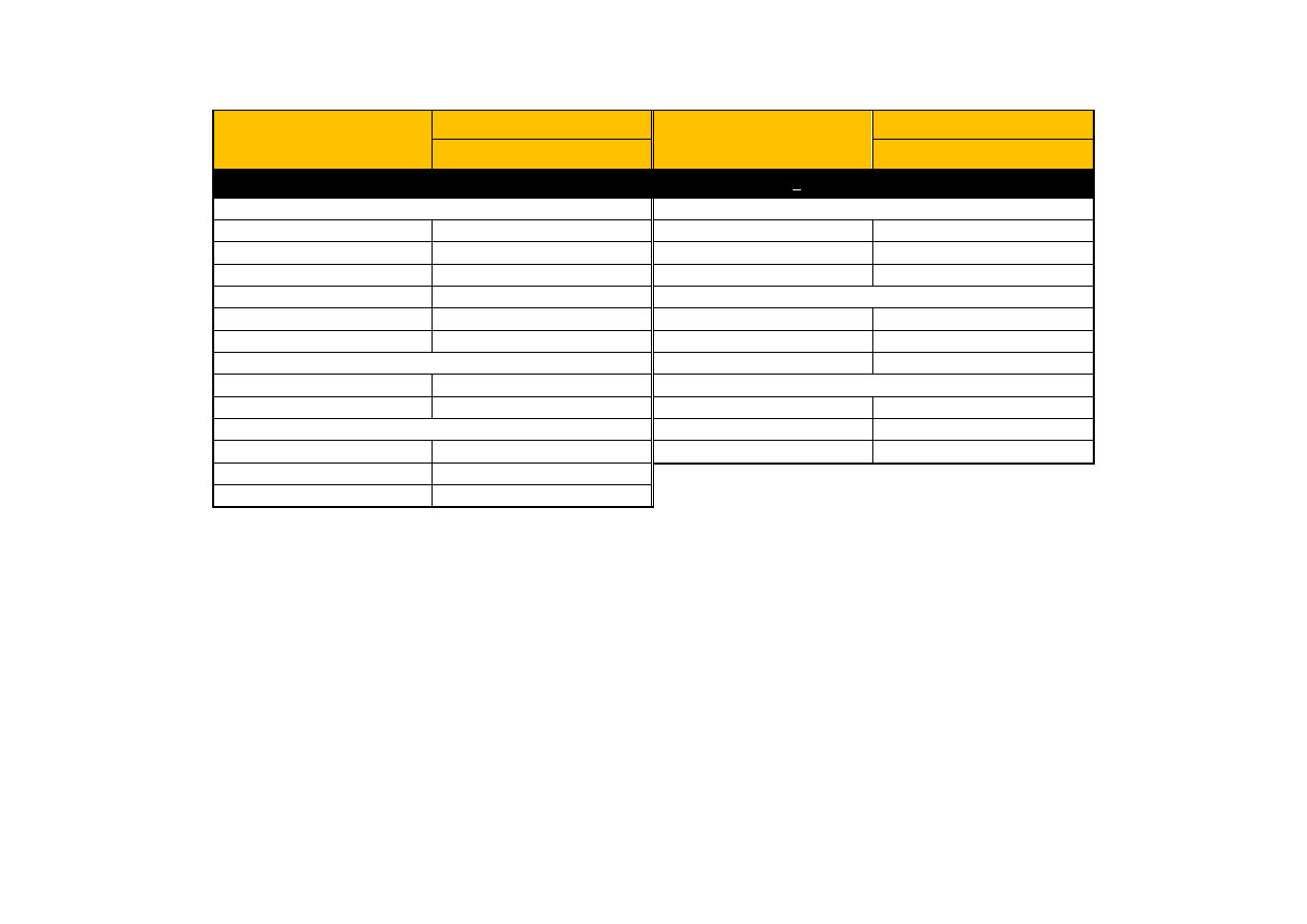
Technical Specifications
DC INPUT FUSE RATINGS (EUROPE)
Product Code
Input Fuse Rating (A)
Product Code
Input Fuse Rating (A)
NORMAL DUTY
NORMAL DUTY
400V BUILD VARIANT
380-480V ±10%, 50/60Hz +5%*
Frame D
Frame G
740-4D0004…
10A
740-4G0045…
70A
740-4D0005…
10A
740-4G0060…
100A
740-4D0006…
16A
740-4G0073…
100A
740-4D0008…
16A
Frame H
740-4D0010…
20A
740-4H0087…
150A
740-4D0012…
20A
740-4H0105…
175A
Frame E
740-4H0145…
200A
740-4E0016…
32A
Frame J
740-4E0023…
40A
740-4J0180…
300A
Frame F
740-4J0205…
350A
740-4F0032…
50A
740-4J0260…
400A
740-4F0038…
50A
740-4F0045…
70A
Type: Semiconductor protection fuses 700V DC, Mersen type A70QSX or equivalent.