Parker Variable Speed Drive AC30 series. User’s Manual (2017) - page 8
 

  Index      Manuals     Parker Variable Speed Drive AC30 series. User’s Manual (2017)


Search            copyright infringement  


Content      ..     6      7      8      9     ..


Parker Variable Speed Drive AC30 series. User’s Manual (2017) - page 8


7-2 

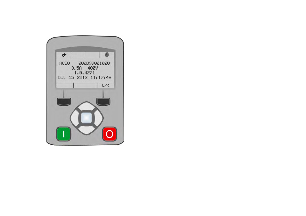
The Graphical Keypad  


Overview 


The top line of the display is used to show the inverter status 


The central region of the display shows the selected parameters or navigation menu 


The bottom line of the display indicates the action associated with the soft keys 


The actions of the soft keys are context dependent 


The central navigation and editing keys are referred to as UP, DOWN, LEFT, RIGHT and 
OK 


The Run, (green), and Stop, (red), keys are used to start and stop the motor when the 
inverter is in local control mode. 


The Graphical Keypad  

7-3


AC30

Keypad 

The nine keys of the Graphical Keypad are divided into three groups. These are the Run and Stop keys, the soft keys and the central navigation 
and editing keys  


Key 

Operation  Description 


RUN 

Only operates when Local start / stop control mode is active 

Control


Runs the motor 


STOP 

Control


Stops the motor when local start / stop control mode is active. 

Trip reset


Resets any trips.


Soft Key 1 


Navigation


Displays the previous level’s menu 

Edit


Aborts the edit, leaving the value unchanged


Soft Key 2 


Welcome 

Lock password and / or Save changes 

Navigation 

Use selected by 1794 Soft Key 2 Mode. 

Attributes 

Used to add or remove a parameter from the Favorites menu 


OK 

Navigation 

Displays the next menu level or parameter. 


Changes to edit mode when a parameter is selected. 

Edit 


Accepts the value of the displayed parameter 

Long Press, (greater than 1s): Displays information about the selected parameter. 


UP 

Navigation 

Moves up through the list of parameters 

Edit 


Increments the value of the displayed parameter 


DOWN 

Navigation 

Moves down through the list of parameters 

Edit 


Decrements the value of the displayed parameter 


LEFT 

Navigation 

Displays the previous level’s menu  

Edit 


Selects the digit to be changed 


RIGHT 

Navigation 

Displays the next menu level or parameter 

Edit 


Selects the digit to be changed 

7-4 

The Graphical Keypad  

The Display 

The display is divided into three areas. The top line shows a summary of the inverter status, the centre region is the main work area and the 
bottom line is used to indicate the action associated with the soft keys. 

INVERTER STATUS SUMMARY 

The top line of the display shows a summary of the inverter status. This is divided into four regions. Each region is dedicated to a particular status 
indication, as shown. 

Left side 


Right side 

Run, stop and direction 

Trip 

Ethernet 

Control source 

 
The individual status conditions are indicated pictorially: 

Run, Stop and Direction 

Running in the positive direction 


Running in the negative direction 


Stopped, (ready to run in the positive direction) 


Stopped, (ready to run in the negative direction) 


Trip 

Inverter tripped, (indication flashing) 


Warning 


Ethernet 

IP Address missing, (indication flashing) 

IP Address configured 


Control source 

Start / stop control from the keypad 


Start / stop control from the terminals 


Start / stop control from a communications master 


The Graphical Keypad  

7-5


AC30

SOFT KEY ACTION INDICATION 

The use of Soft Key 1 and Soft Key 2 is indicated on the bottom line of the display by the icon 
shown above the key. 

Soft Key 1 

Return: 


Abort 


Set-up 


When navigating around the menu tree, the return function navigates to the previous level. In 
this case the return is the opposite of the OK key. 

When changing a parameter value the Abort key discards any modifications and leaves the 
parameter unchanged. 

The Set-up icon is shown on the Welcome page of the GKP. Pressing this starts the set-up 
wizard, (Chapter 9) 

Soft Key 2 

Description 

Notes 

Icon 

Reset GKP entered password, (lock parameters) 


Save parameters 


Toggle between Local and Remote modes 


Change direction, (Local Sequencing only) 


Toggle parameter “Soft Key 2 Value”, present value 0 


Toggle parameter “Soft Key 2 Value”, present value 1 


Add parameter to favorites menu 


Remove parameter from favorites menu 


1.  Feature available in the “Welcome” screen. 
2.  Feature available while navigating menus or parameters, (not while editing parameters). 
3.  Feature available while viewing parameter attributes 

Soft Key 1 

Soft Key 2 

7-6 

The Graphical Keypad  

LEDS 

The Graphical Display has two light emitting diodes, one illuminates the green run key, and one illuminates the red stop key. Each LED may be 
independently off, on or flashing.  

Run key LED 

Stop key LED 

Description 


OFF 

Flashing 

Stopping 

OFF 

ON 

Stopped 

ON 

OFF 

Running 

Flashing 

OFF 

Auto Restart pending 

Both flashing 

The inverter is not in its OPERATIONAL 
state 

Flashing Green then Red 

The inverter is in a FAULT state 

The Graphical Keypad  

7-7


AC30

The Menu System  

NAVIGATING THE MENU SYSTEM 

The Menu System can be thought of as a map which is navigated using the 
direction keys.  


Use the left and right keys to navigate through the menu levels. 


Use the up and down keys to scroll through the Menu and Parameter lists 

 
Menus can contain other menus at a lower level in the tree structure, parameters or 
a mixture of both. 
 
The keys can be used as above to select a parameter. A parameter has a 
selection, (ie: TRUE / FALSE), or a value displayed below the parameter name. 
 

HINT: 

Remember that because the Menu and Parameter lists are looped, the UP 

key can quickly move you to the last Menu or Parameter in the loop. The keys will 
repeat if you hold them down. This is an easy way to step through and view a 
menu’s contents. 

CHANGING A PARAMETER VALUE 

With the parameter you want to change selected, press the center OK key to 
change to Edit mode. In this mode the arrow keys now perform different functions. 


Change a selection, (i.e. TRUE / FALSE) using the UP and DOWN keys. 


Change a value as follows: 

o


The UP and DOWN keys increment / decrement the selected digit. 

o


The LEFT and RIGHT keys move the digit selection. 

o


The selected digit is indicated by the cursor. 


The UP and DOWN keys will repeat if you hold them down. 
 
When changing a value, if the abort icon (

) is shown over Soft Key 1, pressing this key will abort the edit, leaving the value unchanged. 

To accept the edited value, press the center OK key. 
Refer to Chapter 8 for a description of the menu items. 

Welcome screen

First menu

Second menu

Last menu

Level 1

Level 2

7-8 

The Graphical Keypad  

Trips and other information displays 

An information message will be displayed when the unit is tripped. To clear the message from the display, press Soft key 1. 

To reset the trip, allowing the inverter to respond to a start command, press the STOP key.  See Chapter 10 Trips & Fault Finding. 

Setting the display language 

The GKP supports multiple languages. The language to be used may be selected as the second entry in the GKP Wizard, (see chapter 9). The 
language is also available as a parameter 

1005 Language

.  

When changing language, there may will be a short delay while the updated text is transferred to the GKP. During this period the GKP will be 
unresponsive. An information message “UPDATING LANGUAGE” is displayed during this process. 

The GKP has the following language files built in as standard: 

English 
French 
German 
Spanish 
Italian 

SETTING THE DISPLAY LANGUAGE TO CUSTOM 

In addition to the built in languages, the GKP supports a Custom language. This selection may be used to modify one of the built in languages or 
to provide the translations for an otherwise unsupported language. To load the custom language into the GKP, place the file called “custom.lang”, 
in the root directory of an SD card. Insert the SD card into the inverter then set 

1005 Language

 to CUSTOM.  

 
Usage Note: 
 

When 

1005 LANGUAGE 

is set to CUSTOM the GKP will always attempt to update its text from the SD card. This can result in the GKP taking 

longer to become active when the inverter is powered on, and whenever the GKP is reconnected to the inverter. To prevent this delay, once the 
GKP has loaded the custom language file, remove the SD card from the inverter, or remove the file “custom.lang” from the SD card. The GKP 
retains the most recently loaded copy of the custom language file in its non-volatile memory. 


8-1 

Menu Organisation    

Chapter 8: 

Menu Organisation 

Menu Map 

The Menu System consists of a series of menus and sub-menus organised into a “tree” structure. Navigate around the tree on the GKP using the 
UP, DOWN, LEFT and RIGHT keys. Individual parameters may be present in the menu tree at more than one location.  Parameters and/or 
menus that are not required or are empty are automatically hidden on the GKP and web page. 

MENU MAP SUMMARY 
 

 Control Screen 
 Setup 


 Quick Setup 


 Application 


 Motor Control 


 Control & Type 


 Motor Nameplate 


 Motor Data PMAC 


 Auto Restart 


 Autotune 


 Pos Fbk Alignment 


 SVC PMAC 


 Regen Control 


 Inputs and Outputs 


 Base IO 


 Option 


 System Board Option 


 SB Encoder Slot1 


 SB Encoder Slot2 


 Communications 


 Base Ethernet 


 Base Modbus 


 Option 


 PTP 


 Peer to Peer 


 Clone 


 Environment 

 Monitor 


 Quick Monitor 


 Application 


 Motor & Drive 


 Inputs and Outputs 


 System Board 


 Encoder Slot 1 


 Encoder Slot 2 


 Communications 


 Base Ethernet 


 Base Modbus 


 Option 


 PTP 


 Peer to Peer 


 Energy Meter 


 Trips 

   Regen Control 

 Favourites 
 Parameters* 

 
* The “Parameters” menu is intended for expert use only, see Appendix D


Menu Organisation 

8-2


Menu Descriptions 

CONTROL SCREEN 

In local sequencing mode the Control Screen menu shows the Local Setpoint, the Seed Feedback and configuration of the action of the Run key 
and direction. When the inverter is not in local sequencing mode this menu shows the operating speed. The contents of the Control Screen can 
be modified by the configuration. 

SETUP 

Parameters that may require modification once the Setup Wizard is complete. 

MONITOR 

This menu contains parameters commonly used to verify the correct operation of the inverter and the process. 

FAVOURITES 

The Favourites menu contains up to 20 parameters selected for ease of access. 
 

To Add a Parameter to the Favourites Menu 

Using the GKP, navigate to the parameter of interest. 
Press and hold the OK key until the Attributes screen is shown, (hold for about 2s) 
then this appears 

and press the “Add to Favourites” soft key. 


To Remove a Parameter From the Favourites Menu 

Using the GKP navigate to the parameter of interest in the Favourites menu.  
Press and hold the OK key until the Attributes screen is shown, (hold for about 2s).  
Press the “Remove from Favourites” soft key,

.  


PARAMETERS 

A complete collection of all the parameters in the inverter. This menu is intended for expert use. 
 

 or 

is shown here 

Press Soft Key 2 to add to or remove 

from Favourites 

OK Key 


8-3 

Menu Organisation    

Parameter Map 

The following table shows the parameters as they appear in order on the Web page and GKP. Also shown is the Parameter Number, PNO. This 
is a unique reference for each parameter. For more details about each parameter refer to Appendix D. 


 Control Screen 


 Setup 


 Quick Setup 


 Application 


 Motor Control 


 Control and Type 


Motor Type or AFE 

0511 


Control Strategy 

0512 


Control Type 

1533 


Encoder Feedback 

1743 


100% Speed in RPM 

0464 


Acceleration Time 

0486 


Deceleration Time 

0487 


Current Limit 

0305 


Main Torque Lim 

0417 


Seq Stop Method SVC 

1257 


Seq Stop Method VHz 

0484 


Stop Ramp Time 

0504 


VHz Shape 

0422 


Fixed Boost 

0447 


Duty Selection 

0390 


 Motor Nameplate 


Base Frequency 

0457 


Rated Motor Current 

0455 


Motor Poles 

0458 


Base Voltage 

0456 


Nameplate Speed 

0459 


Power Factor 

0461 


Motor Power 

0460 


 Motor Data PMAC 


PMAC Max Speed 

0555 


PMAC Max Current 

0556 


PMAC Rated Current 

0557 


PMAC Rated Torque 

0558 


PMAC Motor Poles 

0559 


PMAC Back Emf Const KE 

0560 


PMAC Base Volt 

1387 


PMAC Winding Resistance 

0561 


PMAC Winding Inductance 

0562 


PMAC Torque Const KT 

0563 


PMAC Encoder Offset 

1808 


PMAC Wiring 

1809 


PMAC Therm Time Const 

0565 


PMAC Motor Inertia 

0564 


 Auto Restart 


AR Enable 

1469 


AR Mode 

1470 


AR Max Restarts 

1471 


AR Trip Mask 

1472 


AR Trip Mask 2 

0796 


AR Initial Delay 

1505 


AR Repeat Delay 

1506 


 Autotune 


Autotune Enable 

0255 


Autotune Mode 

0256 


Nameplate Mag Current 

1550 


Autotune Test Disable 

0257 


Autotune Ramp Time 

0274 


ATN PMAC Test Disable 

1388 


ATN PMAC Ls Test Freq 

1405 


 SVC PMAC 


PMAC SVC Start Cur 

0478 


PMAC SVC Start Speed 

0479 


 Pos Fbk Alignment 


Alignment Enable 

1798 


Alignment On Power On 

1796 


Alignment Method 

1797 


Alignment Level 

1799 


Alignment Ramp Time 

1800 


Alignment On Motor 

1801 


 Regen Control 


Motor Type or AFE 

0511 


AFE Inductance 

1730 


AFE VDC Demand 

1711 


AFE Current Control 

1693 


AFE Iq Demand 

1705 


AFE Id Demand 

1704 


 Inputs and Outputs 


 Base IO 


Anin 01 Type 

0001 


Anin 01 Offset 

0957 


Anin 01 Scale 

0958 


Anin 02 Type 

0002 

Menu Organisation 

8-4


Anin 02 Offset 

0959 


Anin 02 Scale 

0960 


Anout 01 Type 

0003 


Anout 01 Scale 

0686 


Anout 01 Offset 

1108 


Anout 01 ABS 

1441 


Anout 02 Type 

0004 


Anout 02 Scale 

1460 


Anout 02 Offset 

1467 


Anout 02 ABS 

1468 


 Option 


Option IO Required 

1178 


Thermistor Type 

1184 


Encoder Supply 

1511 


Encoder Lines 

1512 


Encoder Invert 

1513 


Encoder Type 

1514 


Encoder Single Ended 

1515 


Encoder Count Reset 

1517 


Resolver Frequency 

1791 


Resolver Voltage 

1790 


Resolver Ratio 

1792 


Resolver Max Speed 

1825 


Resolver Poles 

1793 


Resolver Built-In Gear 

1822 


Resolver Invert 

1810 


Resolver Speed Filter 

1815 


Resolver Min Filter 

1851 


Resolver Resolution 

1816 


Anin 11 Offset 

1461 


Anin 11 Scale 

1462 


Anin 12 Offset 

1463 


Anin 12 Scale 

1464 


Anin 13 Offset 

1465 


Anin 13 Scale 

1466 


 System Board Option 


System Board Required 

1739 


Output Enable 

1678 


Output Source 

1679 


Output Voltage 

1680 


Output A 

1756 


Output B 

1757 


Output Z 

1758 


Synth Encoder Lines 

1696 


Synth Encoder Speed 

1698 


Synth Encoder Invert 

1702 


 SB Encoder Slot1 


Encoder Supply 

1663 


Encoder Lines 

1664 


Encoder Invert 

1665 


Encoder Type 

1666 


High Input Threshold 

1667 


Encoder Count Reset 

1669 


 SB Encoder Slot2 


Encoder Lines 

1671 


Encoder Invert 

1672 


Encoder Type 

1673 


High Input Threshold 

1674 


Encoder Count Reset 

1676 


 Communications 


 Base Ethernet 


DHCP 

0929 


Auto IP 

0930 


User IP Address 

0933 


User Subnet Mask 

0934 


User Gateway Address 

0935 


Web Access 

0944 


 Base Modbus 


Maximum Connections 

0939 


High Word First 

0940 


Modbus Timeout 

0941 


Modbus Trip Enable 

0942 


Modbus Mapping[16] 

1567 


Modbus TCP Password 

1659 


 Option 


Comms Required 

0044 


BACnet MAC Address 

1091 


BACnet MSTP Device ID 

1092 


BACnet Baud Rate 

1093 


BACnet MSTP Timeout 

1094 


BACnet IP Device ID 

0209 


BACnet IP Timeout 

0210 


CANopen Node Address 

0212 


CANopen Baud Rate 

0213 


ControlNet MAC ID 

0215 


DeviceNet MAC ID 

0219 


DeviceNet Baud Rate 

0220 


Modbus Device Address 

0229 


Modbus RTU Baud Rate 

0230 


Parity And Stop Bits 

0231 


High Word First RTU 

0232 


Modbus RTU Timeout 

0233 


High Word First TCP 

0235 


Profibus Node Address 

0238 


Modbus TCP Timeout 

0236 


Address Assignment 

0199 

8-5 

Menu Organisation    


Fixed IP Address 

0200 


Fixed Subnet Mask 

0201 


Fixed Gateway Address 

0202 


Option Web Enable 

0203 


Web Parameters Enable 

0204 


Option FTP Enable 

0205 


Option FTP Admin Mode 

0206 


IPConfig Enable 

0207 


Comms Trip Enable 

0048 


Comms Reset Allow 

1853 


BACnet Max Master 

1095 


BACnet Max Info Frames 

1096 


DNet Producing Inst 

0222 


DNet Consuming Inst 

0223 


CNet Producing Inst 

0216 


CNet Consuming Inst 

0217 


ENet Producing Inst 

0226 


ENet Consuming Inst 

0227 


Modbus Password 

1640 


Read Mapping[32] 

0055 


Write Mapping[32] 

0120 


 PTP 


PTP Enable 

1661 


PTP Clock Type 

1684 


PTP Clock Mode 

1683 


PTP Domain Number 

1787 


PTP Log Sync Interval 

1681 


PTP Priority2 

1686 


PTP Lock Threshold 

1685 


 Peer to Peer 


Peer to Peer Enable 

1725 


Destination IP Address 

1726 


Destination Port 

1727 


Local Port 

1728 


 Clone 


Clone Filename 

1534 


Clone Direction 

1537 


Full Restore 

1538 


Application 

1539 


Power Parameters 

1541 


Other Parameters 

1540 


Clone Start 

1542 


Clone Status 

1543 


 Environment 


Drive Name 

0961 


GKP Password 

1142 


Web Access 

0944 


Display Timeout 

0983 


Startup Page 

0982 

 Monitor 


 Quick Monitor 


 Application 


 Motor and Drive 


Actual Speed RPM 

0393 


DC Link Voltage 

0392 


Actual Speed rps 

0394 


Actual Speed Percent 

0395 


DC Link Volt Filtered 

0396 


Actual Torque 

0399 


Actual Field Current 

0400 


Motor Current Percent 

0401 


Motor Current 

0402 


Motor Terminal Volts 

0405 


Actual Pos Torque Lim 

0420 


Actual Neg Torque Lim 

0421 


Heatsink Temperature 

0407 


CM Temperature 

0406 


PMAC Wiring 

1809 


 Inputs and Outputs 


Digout Value 

0022 


Digin Value 

0005 


Anout 01 Value 

0042 


Anout 02 Value 

0043 


Anin 01 Value 

0039 


Anin 01 Break 

0040 


Anin 02 Value 

0041 


Anin 11 Value 

1181 


Anin 12 Value 

1182 


Anin 13 Value 

1183 


Encoder Speed 

1516 


Encoder Count 

1518 


SB Digital Input 1 

1759 


SB Digital Input 2 

1722 


SB Digital Input 3 

1723 


Resolver Speed % 

1814 


resolver position 

1824 


Resolver Turns 

1811 


Resolver Fraction Turns 

1812 


 System Board 


 Encoder Slot 1 


Encoder Speed 

1668 


Encoder Count 

1670 


 Encoder Slot 1 


Encoder Speed 

1675 


Encoder Count 

1677 


 Communications 


Menu Organisation 

8-6


 Base Ethernet 


Ethernet State 

0919 


MAC Address 

0920 


IP Address 

0926 


Subnet Mask 

0927 


Gateway Address 

0928 


 Base Modbus 


Open Connections 

1241 


Process Active 

0943 


Mapping Valid 

1632 


 Option 


Comms Fitted 

0045 


BACnet MSTP State 

1089 


BACnet IP State 

0208 


Profibus State 

0237 


EtherNet IP State 

0225 


Modbus TCP State 

0234 


Modbus RTU State 

0228 


EtherCAT State 

0224 


PROFINET State 

0239 


PROFINET Device Name 

0240 


CANopen State 

0211 


ControlNet State 

0214 


DeviceNet State 

0218 


CANopen Actual Baud 

1251 


DeviceNet Actual Baud 

0221 


Comms Supervised 

0047 


Comms Event Active 

0186 


Option MAC Address 

0189 


Option IP Address 

0195 


Option Subnet Mask 

0196 


Option Gateway 

0197 


Option DHCP Enabled 

0198 


Comms Module Version 

0049 


Comms Module Serial 

0050 


Comms Diagnostic 

0051 


Comms Diagnostic Code 

0052 


Comms Exception 

0053 


Comms Net Exception 

0054 


 PTP 


PTP State 

1689 


PTP Clock 

1699 


PTP Offset 

1687 


PTP Locked 

1688 


 Peer to Peer 


Peer to Peer State 

1729 


 Energy Meter 


Energy kWh 

0383 


Power kW 

0380 


Power HP 

0381 


Reactive Power 

0382 


Power Factor Est 

0385 


 Trips 


First Trip 

0696 


Active  1 - 32 

0763 


Active 33 - 64 

0513 


Warnings  1 - 32 

0829 


Warnings 33 - 64 

0514 


RTA Code 

0998 


RTA Data 

0999 


 Regen Control 


AFE Sync Frequency 

1703 


AFE Status 

1721 


DC Link Voltage 

0392 

Favourites 


9-1 

Setup Wizard    

Chapter 9: 

Setup Wizard 

GKP Setup Wizard 

Purpose of the Setup Wizard 

The purpose of the setup wizard is to configure the inverter in a clear and concise manner.  

First familiarize yourself with Chapter 7  Graphical Keypad, for the keypad functions. 

Starting the Setup Wizard 

The Setup Wizard is automatically invoked when first powered up. The setup wizard may be invoked at any 
other time by pressing the set-up key (

). This is shown on the Welcome Screen, (at the “top” of the MMI 

menu structure). The Setup Wizard is also invoked by  changing the parameter “Run Wizard?” to YES (you will 
find this under the “Parameters: Device Manager: Setup Wizard" menu). 

Running the Setup Wizard 

At each point in the wizard pressing the 

OK key

 selects the displayed value and moves on to the next step.  

 
Pressing 

Soft key 1

 moves back a step. Pressing the UP and DOWN keys modifies the selected value. 

 
The default setting for all parameters depends on earlier answers and on the physical configuration of the inverter so pressing OK repeatedly will 
result in no parameter values being altered.  All data entered is automatically saved without the need for any additional commands. 

Information that you will need in order to set up the motor control 

When you run the setup wizard you will be asked for various items of information in order to set up the motor control. 

OK key 

Soft Key 1 

Setup Wizard  

9-2


Setup Wizard Stages 

 
The Setup Wizard is divided into sections. With the exception of the first group of parameters, each section may be skipped. The first group of 
parameters sets the inverter operating environment. 
 

PNO 

Parameter 

Comment 

1141  View Level 

Select the view level, Operator, Technician or Engineer. 

1005  Language 

Select the required language to be used on the GKP. There may be a slight pause while the inverter adopts the 
selected language. 

1002  Update Firmware 

Select YES to update the inverter’s firmware. Only visible in Engineering view mode with a firmware file on the SD 
Card. 

1006  Run Wizard 

Select YES to continue. Select NO to exit with the new settings for View Level and Language 

1000  Reset to Defaults 

Changing this parameter to TRUE then pressing OK resets all parameters back to the default value determined by 
the inverters hardware configuration. If this choice is left FALSE all parameters retain their previously set values.  

1186  Time and Date 

Only shown if an IO option with RTC hardware is fitted. 

0944  Web Access 

Set to FULL to allow access to parameter values via the web page. 

1738  Enable Auto Save 

Set to TRUE to automatically save parameter values as they are entered on the GKP and Web page. Set to 
FALSE to enable the manual save feature. 
All parameters are saved on completion of the GKP wizard regardless of the setting of this parameter. Also, this 
parameter is always saved when changed. 

0961  Drive Name 

Defaults to show the Ethernet MAC address 

9-3 

Setup Wizard    

Application selection 

Selection of the specific Macro and associated parameters. 


PNO 

Parameter 

Validity 

Comment 

  Setup Application? 


Select YES to configure the application parameters, NO to skip this section 

1900  Selected Application 

BA

SI

C

 SP

E

ED


CO

NT

RO

L


AU

T

O

/M

AN

U

AL


CO

NT

RO

L


SP

EE

D


R

AI

SE/

L

O

W

ER


SP

EE

D


PR

E

S

ET

S


PR

O

C

E

S

S PI

D


AF

E


1937  Disable Coast Stop 

● 

● 

● 

● 

●   


1938  Disable Quickstop 

● 

● 

● 

● 

●   


1901  RL Ramp Time 


● 


Sets the rate of change of the output of the Raise/Lower ramp. 

1902  RL Reset Value 


● 


The value of the Raise/Lower ramp output when reset. 

1903  RL Maximum Value 


● 


The upper limit of the Raise/Lower ramp output. 

1904  RL Minimum Value 


● 


The lower limit of the Raise/Lower ramp output 

1916  Preset Speed 0 


● 


The preset speed output when the selected preset is 0. 

1917  Preset Speed 1 


● 


The preset speed output when the selected preset is 1. 

1918  Preset Speed 2 


● 


The preset speed output when the selected preset is 2. 

1919  Preset Speed 3 


● 


The preset speed output when the selected preset is 3. 

1920  Preset Speed 4 


● 


The preset speed output when the selected preset is 4. 

1921  Preset Speed 5 


● 


The preset speed output when the selected preset is 5. 

1922  Preset Speed 6 


● 


The preset speed output when the selected preset is 6. 

1923  Preset Speed 7 


● 


The preset speed output when the selected preset is 7. 

1926  PID Setpoint Negate 


●   

Changes the sign of the setpoint input. 

1927  PID Feedback 

Negate 


●   

Changes the sign of the feedback input. 

1928  PID Prop Gain 


●   

The proportional gain of the PID controller. 

1929  PID Integral TC 


●   

The integral time constant of the PID controller. 

1930  PID Derivative TC 


●   

The derivative time constant of the PID controller. 

1931  PID Output Filter TC 


●   

The time constant of the first order filter used to filter the PID output. 

1932  PID Output Pos Limit 


●   

The maximum positive excursion, (limit), of the PID controller. 

1933  PID Output Neg Limit 


●   

The maximum negative excursion, (limit), of the PID controller. 

1934  PID Output Scaling 


●   

The overall scaling factor which is applied after the positive and negative limit 
clamps 


Content      ..     6      7      8      9     ..