Parker 590+ series Frame 1, 2, 3, 4, 5, 6 & H. Product Manual (2012) - page 10

4-20 Operating the Drive
Starting and Stopping Methods
Stopping Methods
• If the Drive is “non-regenerative” (2-quad - 591+) it effectively coasts to a stop once the current demand reverses.
• If the Drive is “regenerative” (4-quad - 590+) then it can stop faster because it uses energy from the load, i.e. reverse current is allowed to flow.
Normal Stop and Program Stop are only relevant for a “regenerative” controller.
The parameters STOP TIME and PROG STOP TIME have associated timers which initiate a Coast Stop after the timed
period.
MMI Menu Map
1 SETUP PARAMETERS
The Coast Stop has direct control of the Run relay with no intervening electronics.
2 STOP RATES
All associated parameters can be found in the STOP RATES menu.
Terminal
Description
Function
Parameter
Priority
B9
Coast Stop
Motor coasts to rest
--
Overrides Program Stop and Normal Stop
B8
Program Stop
Motor decelerates at Program Stop rate
PROG STOP TIME
Overrides Normal Stop
C3
Start/Run
Motor decelerates at Normal Stop rate
STOP TIME
--
(Normal Stop)
Normal Stop (C3)
MMI Menu Map
This is achieved by removing 24V from Terminal C3.
1 SETUP PARAMETERS
The motor speed is brought to zero in a time defined by the STOP TIME parameter.
2 STOP RATES
STOP TIME
MMI Menu Map
During Normal Stop, the current is limited by the MAIN CURR. LIMIT parameter
1 SETUP PARAMETERS
2 CURRENT LOOP
MAIN CURR.LIMIT
Operating the Drive 4-21
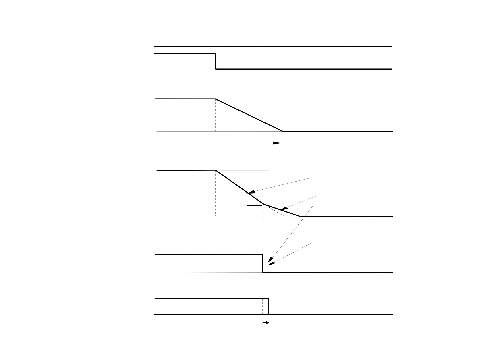
NORMAL STOP
SPEED SETPOINT (100%)
Control Signals
START / RUN (C3)
t
0%
SPEED DEMAND
100% = SPEED SETPOINT
Speed Demand
t
0%
STOP TIME
DEFAULT 10.0 SEC
SPEED FEEDBACK
= SPEED SETPOINT
Actual Speed
ACTUAL STOPPING RATE
DEPENDS ON LOAD INTERTIA,
MOTOR HP AND OVERLOAD
CAPABILITY OF MOTOR/DRIVE
DRIVE IS DISABLED BELOW
STOP ZERO SPEED
IF SET > 0.25%
STOP ZERO
SPEED
(DEFAULT 2%)
t
0%
DRIVE REMAINS ENABLED
FOR CONTACTOR DELAY
IF STOP ZERO SPEED < 0.25%
Enable
DRIVE ENABLE =ENABLED
(DISPLAY DIAGNOSTIC)
t
0%
DRIVE ENABLE = DISABLED
Indicators
DRIVE RUN LED
AND START CONTACTOR
t
0%
CONTACTOR DELAY
(DEFAULT 1.0 SECS)
4-22 Operating the Drive
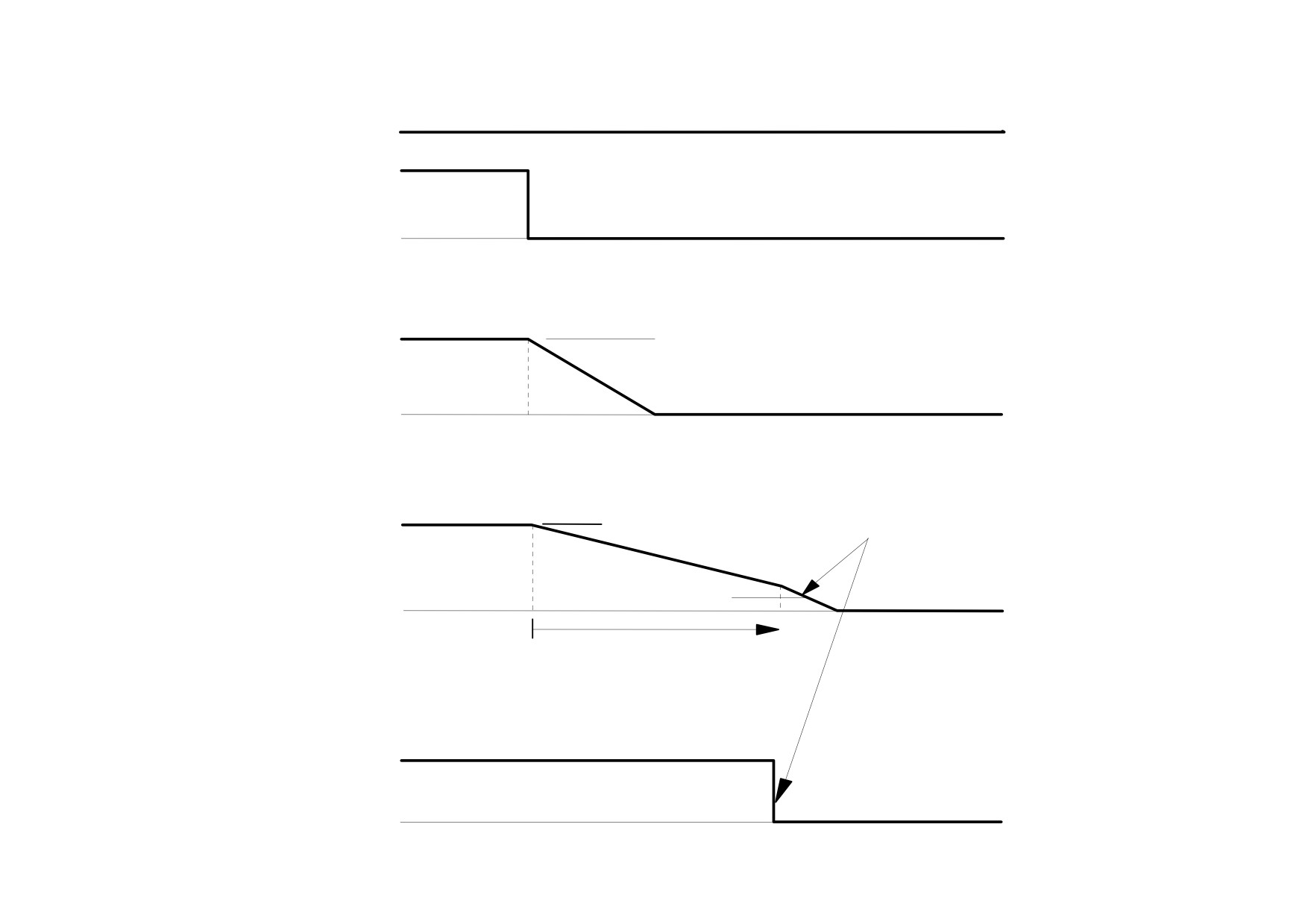
TIME-OUT IN NORMAL STOP
SPEED SETPOINT
Control Signals
START/RUN (C3)
t
0%
SPEED SETPOINT
SPEED DEMAND
Speed Demand
t
0%
CONTACTOR WILL DROP OUT
IF SPEED FEEDBACK > STOP ZERO SPEED
= SPEED SETPOINT
WHEN STOP LIMIT TIMED OUT
SPEED FEEDBACK
Actual Speed
STOP ZERO SPEED
(DEFAULT 2% )
t
0%
STOP LIMIT ( DEFAULT 60.0 SEC )
Indicators
DRIVE RUN LED
AND START CONTACTOR
DRIVE ENABLE =ENABLED
t
DRIVE RUN LED & START CONTACTOR
0%
DRIVE ENABLE =DISABLED

Operating the Drive 4-23
MMI Menu Map
Program Stop (B8)
1 SETUP PARAMETERS
This is achieved by removing 24V from Terminal B8.
2 STOP RATES
The motor speed is brought to zero under conditions defined by the PROG. STOP TIME (ramp rate) and PROG. STOP I
PROG. STOP TIME
LIMIT parameters.
PROG. STOP I LIMIT
4-24 Operating the Drive
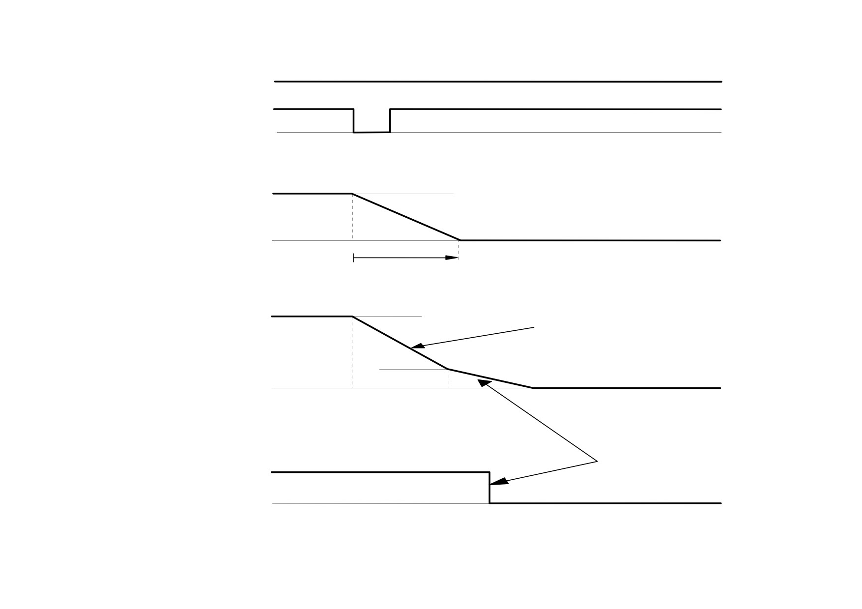
PROGRAM STOP TIMING
SPEED SETPOINT ( 100% )
Control Signals
PROGRAM STOP
LED ON ( PROGRAM STOP FALSE )
LED
(PROGRAM STOP IS A
OFF
LATCHED FUNCTION)
t
0%
SPEED DEMAND
100% = SPEED SETPOINT
Speed Demand
t
0%
PROG STOP TIME
DEFAULT 0.1 SEC
SPEED FEEDBACK
= SPEED SETPOINT
CURRENT LIMIT SET BY
Actual Speed
PROG STOP I LIMIT
( DEFAULT 100% )
ACTUAL STOPPING RATE DEPENDS
STOP ZERO
ON LOAD INERTIA, MOTOR HP AND
SPEED
OVERLOAD CAPABILITY OF MOTOR/DRIVE
(DEFAULT 2%)
t
0%
DRIVE IS DISABLED
AND CONTACTOR
TURNS OFF BELOW
Indicators
DRIVE RUN LED
STOP ZERO SPEED
AND START CONTACTOR
t
DRIVE ENABLE =ENABLED
DRIVE RUN LED AND START CONTACTOR
0%
DRIVE ENABLE =DISABLED
Operating the Drive 4-25
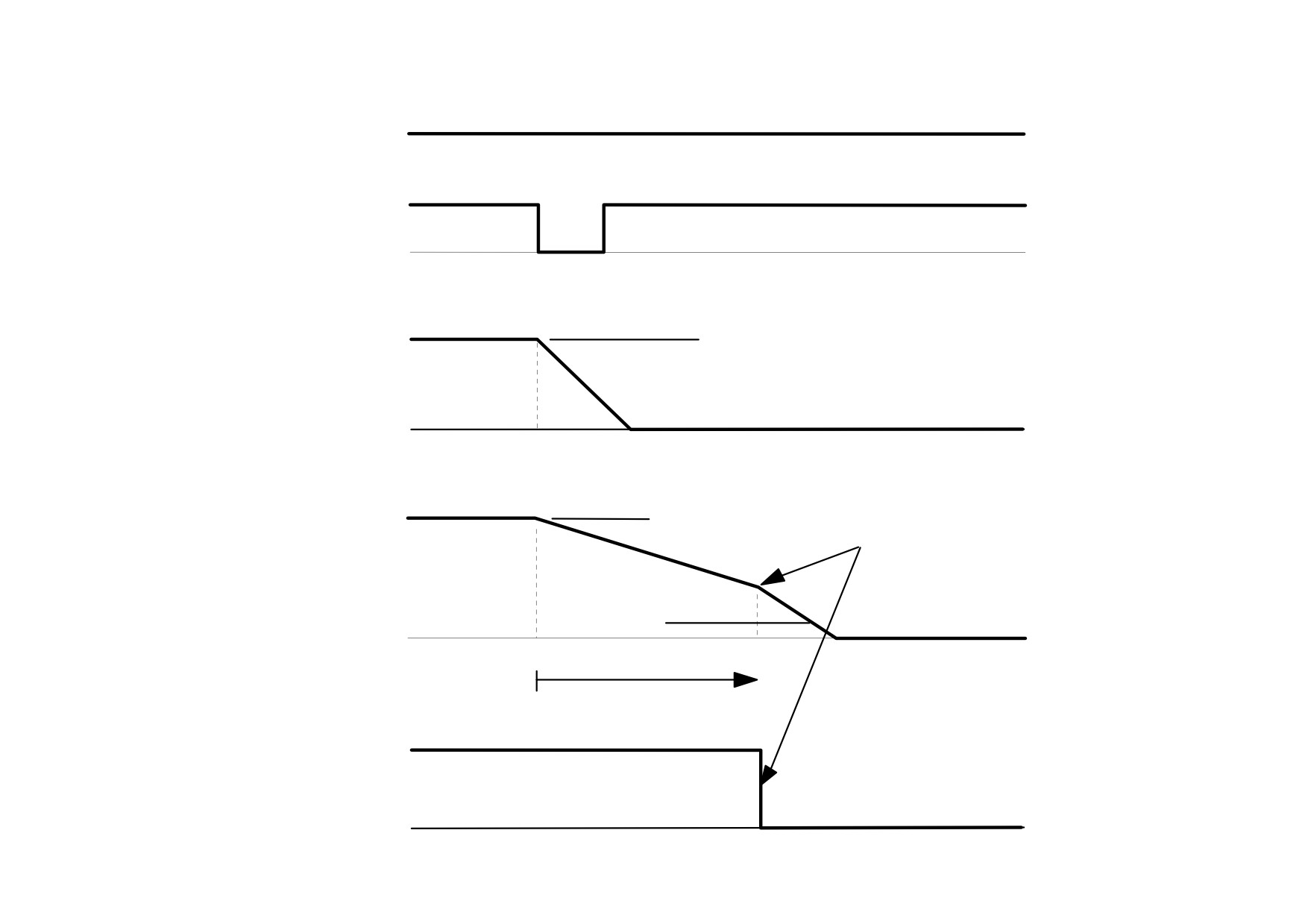
TIME-OUT IN PROGRAM STOP
SPEED SETPOINT
Control Signals
LED ON (PROGRAM STOP FALSE )
PROGRAM STOP
LED
OFF
t
0%
SPEED DEMAND
SPEED SETPOINT
Speed Demand
t
0%
CONTACTOR WILL DROP OUT IF
SPEED FEEDBACK
SPEED SETPOINT
SPEED FEEDBACK > STOP ZERO SPEED
WHEN PROG STOP LIMIT TIMED OUT
Actual Speed
STOP ZERO SPEED
( DEFAULT 2% )
t
0%
PROG STOP LIMIT
(DEFAULT 60.0 SEC)
Enable
DRIVE RUN LED AND START CONTACTOR
DRIVE ENABLE =ENABLED
DRIVE RUN LED & START CONTACTOR
t
0%
DRIVE ENABLE =DISABLED

4-26 Operating the Drive
Coast Stop (B9)
This is achieved by removing 24V from Terminal B9.
The stack is automatically quenched and the contactor is opened. The motor coasts to a stop.
NOTE The motor coast stop rate is dictated by the motor inertia - the drive does not control the motion.
MMI Menu Map
1
SETUP PARAMETERS
Standstill
Refer to Appendix D: “Programming” - STANDSTILL.
2
STANDSTILL
STANDSTILL LOGIC
ZERO THRESHOLD
The Trip Condition
When a trip condition is detected, a similar stopping method to Coast Stop is used. The power stack cannot be re-enabled until the trip condition has
been cleared and successfully reset.
Refer to Chapter 7: “Trips and Fault Finding” for further details.
Normal Starting Method
To achieve a normal start of the Drive:
1. Apply 24V to Terminal C5 (Enable)
2. Apply 24V to Terminal C3 (Start)
NOTE The Drive will not start if there are alarms present, or if Terminals B8 (Program Stop) or B9 (Coast Stop) are low, 0V.
Ensure that Program Stop and Coast Stop are valid before Start/Run is applied.

Operating the Drive 4-27
Advanced Starting Methods
Starting Several Drives Simultaneously
1. Apply 24V to Terminal C3 (Start)
2. Use Terminal C5 (Enable) to synchronise the start-up of the Drives
Jog
NOTE The Drive will not start if there are alarms present.
This facility provides two dedicated jog setpoints (or perhaps an Inch Forward/Inch Reverse). Activating Jog runs the
motor at speeds set by JOG SPEED 1 or JOG SPEED 2. The JOG/SLACK::MODE parameter selects JOG SPEED 1 or 2.
1. Apply 24V to Terminal C5 (Enable)
2. Apply 24V to Terminal C4 (Jog Mode)
Refer to Appendix D: “Programming” - JOG/SLACK for further information. Also refer to the STOP RATES function
block: the CONTACTOR DELAY parameter is used to prevent multiple operations of the main contactor from rapid use of
the Jog switch.
Crawl
NOTE The Drive will not start if there are alarms present.
This facility provides a dedicated crawl setpoint. Activating Crawl runs the motor at the speed set by CRAWL SPEED.
1. Apply 24V to Terminal C5 (Enable)
2. Set JOG/SLACK::MODE parameter (Tag No. 228) to TRUE.
3. Apply 24V to Terminal C3 (Start) and Terminal C4 (Jog Mode) simultaneously to start the Drive using the crawl
speed, in Forward or Reverse.
When selecting CRAWL, apply Start (C3) and Jog (C4) simultaneously, otherwise you may experience Modes 3 or
6 momentarily. Refer to Appendix D: “Programming” - JOG/SLACK for further information (see the Setpoint
Selection Table).

4-28 Operating the Drive
Take Up Slack
NOTE The Drive will not start if there are alarms present.
This facility provides two additional Take Up Slack setpoints. Activating Take Up Slack runs the motor at the speed set by
"speed setpoint + TAKE UP1" or "speed setpoint + TAKE UP 2".
TAKE UP SLACK 1:
1. Apply 24V to Terminal C5 (Enable).
2. Apply 24V to Terminal C3 (Start) to accelerate to set speed.
3. Set JOG/SLACK::MODE parameter (Tag No. 228) to FALSE.
4. Apply 24V to Terminal C4 (Jog Mode) to run the motor at "speed setpoint + TAKE UP 1".
5. Remove 24V from Terminal C4 (Jog Mode) to run the motor at speed setpoint.
TAKE UP SLACK 2:
6. Apply 24V to Terminal C5 (Enable).
7. Apply 24V to Terminal C3 (Start) to accelerate to set speed.
8. Set JOG/SLACK::MODE parameter (Tag No. 228) to TRUE to run the motor at "speed setpoint + TAKE UP 2".
9. Set JOG/SLACK::MODE parameter (Tag No. 228) to FALSE to run the motor at speed setpoint .
Refer to Appendix D: “Programming” - JOG/SLACK for further information (see the Setpoint Selection Table).

Operating the Drive 4-29
External Control of the Drive
Remote Sequencing Command
REM. SEQUENCE : Tag 536, Mnemonic "ow", Default = 0x0000 ("0x" denotes a Hexadecimal value)
This is a control word that allows the device to be operated remotely over a field bus. REM. SEQ. ENABLE must be TRUE to enable this function.
NOTE
Refer to the RS485 Communications Interface Technical Manual, HA463560 on the website, for information about the EI Bisynch ASCII
communications protocol.
Reserved bits are undefined when read and should be set Zero when written.
Bit Number
Mask
Name
Comment
0 (lsb)
0x0001
Remote Enable
1
0x0002
Remote Start
2
0x0004
Remote Jog
3
0x0008
Remote Jog Mode
Selects Jog Speed
4
0x0010
Reserved
5
0x0020
Reserved
6
0x0040
Reserved
7
0x0080
Reserved
8
0x0100
Remote Alarm Ack
Alarm Acknowledge
9
0x0200
Remote/Remote Trip
Remote Trip (High for OK)
10
0x0400
Reserved
11
0x0800
Reserved
12
0x1000
Reserved
13
0x2000
Reserved
14 (msb)
0x4000
Reserved
15 (msb)
0x8000
Validation
This bit must be zero for the command word to be accepted
4-30 Operating the Drive
Useful Commands using EI Bisynch ASCII - REM. SEQUENCE
Tag 536, Mnemonic "ow", for example:
/Remote Trip
Alarm Ack
Jog Mode
Jog
Start
Enable
Command
Start Drive
1
0
X
0
1
1
ow>0203
Stop Drive
1
0
X
0
0
1
ow>0201
Disable Drive
1
0
X
X
X
0
ow>0200
Jog Setpoint 1
1
0
0
1
0
1
ow>0205
Jog Setpoint 2
1
0
1
1
0
1
ow>020D
Remote Trip
0
0
X
X
X
X
ow>0000
Reset Alarm a)
1
1
0
0
0
0
ow>0300
Healthy Output Bit 11 goes high
Reset Alarm b)
1
0
X
0
0
0
ow>0200

Operating the Drive 4-31
Sequence Status
SEQ STATUS : Tag 537, Mnemonic "ox" (Read Only)
Reserved bits are undefined when read.
Bit Number
Mask
Name
Comment
0 (lsb)
0x0001
Coast Stop
Coast Stop demanded
1
0x0002
Program Stop
Program (Fast) Stop demanded
2
0x0004
Disable
/Enable demanded
3
0x0008
Run
Drive Start demanded
4
0x0010
Jog
Drive Jog demanded
5
0x0020
Reserved
Undefined
6
0x0040
Alarm
Unacknowledged alarm
(Health Store != 0)
7
0x0080
Reserved
Undefined
8
0x0100
Running
Contactor in and drive ready to be enabled
9
0x0200
Enabled
Drive is enabled
10
0x0400
Zero Speed
Zero speed Output TAG 17
11
0x0800
Healthy Output
Healthy Output TAG 12
12
0x1000
Ready
Ready Output TAG 559
13
0x2000
Reserved
Undefined
14
0x4000
Reserved
Undefined
15 (msb)
0x8000
Reserved
Undefined
Typical Bit Patterns reported via SEQ STATUS
Tag 537, Mnemonic "ox" (Read Only) - for example:
Sequence Status
Comment
0x1B0B
Running
0x044B
Tripped, Run High
0x0447
Tripped, Run Low, Enable Low
0x0C47
Trip Acknowledged, Healthy output TRUE Alarm stays high until drive is restarted.
Chapter 5 Control Loops
This chapter explains the principle of operation, and provides help on setting up the control loops correctly.
Control Loops - Principle of Operation
• Current Loop
• Speed Loop
• Field Control

Control Loops
5-1
Control Loops - Principle of Operation
MMI Menu Map
1
SETUP PARAMETERS
NOTE Selection between Current Control or Speed Control (default) is made by the I DMD ISOLATE (current demand
isolate) parameter using Digital I/P3 (Terminal C8). If ENABLED the Drive operates as a current controller, and if
2
CURRENT LOOP
DISABLED (the default) it operates as a speed controller.
I DMD ISOLATE
Current Loop
The current loop accepts a demand from either the speed loop, or directly from the plant, and forms an error signal which is the difference between
demand and average value of feedback. The error signal is fed into a Proportional + Integral compensator which produces the output of the current
loop, i.e. the firing angle signal.
In the Drive, the error signal is created in two different forms:
1. The average error is computed as the difference between demand and average value of feedback and fed into the Integral part of the P + I
algorithm.
2. The instantaneous error is computed as the difference between demand and instantaneous value of feedback and is fed into the Proportional part of
the P + I algorithm. This gives higher transient performance since it does not contain any time lag, unlike the average which has a built-in lag of 1/6
of mains cycle. However, the average is the true measurement of torque which is the objective of the current control and this is not affected by the
small time lag in achieving zero steady-state error.
The firing angle signal is translated into a certain time delay from the mains zero cross point (obtained via a Phase-Lock-Loop) and this results in a
firing command being issued to the thyristor stack every 1/6 of a mains cycle in steady-state.
Some special features of the current controller are discussed separately below.
Adaptive Current Control
The gain of a thyristor 6-pulse converter (voltage-time area over firing angle) drops dramatically at discontinuous values of armature current.
Therefore a gain boost is required in the current controller to compensate for that.
In the Drive, this is handled by an adaptive algorithm which allows the current to follow the demand in one step (firing) within the discontinuous
region of operation.
Back EMF (BEMF) Estimate
With the motor at standstill, the firing angle for zero current is 120 degrees. When the motor is rotating at different speeds the firing angle for zero
current follows a cosine locus.
It is of paramount importance to track this locus as close as possible throughout the speed range if the current loop bandwidth is to be maintained at its
highest possible level during current reversals from master to slave bridge and visa-versa.
There are two reasons for the loss of bandwidth at current reversals:
5-2 Control Loops
1. The loss of converter gain needs to be compensated in an accurate way which is the objective of the adaptive algorithm.
2. The above algorithm also relies on the right start-up value of firing angle in the incoming bridge in order to minimise both the "dead-time"
(time interval of zero current referred to below) as well as the rise time to the required current demand.
In order to get the right start-up value of firing angle the knowledge of the operating BEMF is necessary. In the Drive, this is achieved by a
combination of a hardware peak current detector and appropriate software algorithm.
Bridge Changeover Delay
The bridge changeover "dead-time", i.e. time interval of zero current, is programmable from 1 to 1500 (via Reserved Menu) with a default value of 1.
For values from 1 to 6:
The delay can be set at multiples of 1/6 mains period, i.e. max. 6 x 3.33 = 20ms at 50Hz. This is relevant for use with large power converters where it
is advisable to allow more time for snubber currents to subside before reversal is enabled. It is also relevant for motors with very large armature
inductance where zero current detection is more sensitive and therefore a "factor of safety" in the bridge changeover delay is advisable.
For values from 7 to 1500:
The delay corresponds to 7 x 1.33μs up to 1500 x 1.33μs = 2ms maximum.
Manual Tuning
NOTE
This procedure is rarely used or required, if possible use Autotune.
If the motor is permanent magnet or (very rarely) wound-field of relatively high permanent magnetism, and the drive is a 4Q drive, then clamp the
shaft prior to using the 4Q Autotune process (default). This mode of Autotune produces current pulses on alternate thyristor bridges, and thus the net
rotational torque is very low.
There are two circumstances where a manual tuning process would be required:
1. The motor is permanent magnet or (very rarely) wound-field of relatively high permanent magnetism, and the drive is a 2Q drive.
2. The Autotune process has failed with AUTOTUNE ERROR message. The possible causes of an Autotune error are:
• The motor shaft was rotating, or was caused to rotate.
• The field current was seen to exceed 6%, when a field-off Autotune had been selected, or the field current stopped during a field-on
Autotune.
• The drive to armature wiring was open-circuit.
• The discontinuous current boundary was found to exceed 200% of either the stack rating or the nominated motor armature current rating
(see A below).
• Large imbalance in the three-phase voltages of the supply (see B below).
• A hardware fault relating to current feedback was detected on the control board.
If the cause of the Autotune failure can be determined and rectified then do so and simply repeat the Autotune process.
Control Loops
5-3
A.
If a very high motor discontinuous current boundary was the cause of failure, then the discontinuous-region manual tuning process needs to
be applied as follows:
1. Set the DISCONTINUOUS parameter to 0, which selects adaptive current control off. When operating in this mode, disable the Missing
Pulse alarm, since it is normally masked in the discontinuous region, and it will otherwise give spurious trips at low currents.
2. Set PROP. GAIN to a low level (typically 1), since it is ineffectual in the discontinuous current operating region.
3. Set the INT. GAIN to a moderate level (typically 10), sufficient to give fast response throughout the discontinuous current region.
B.
If imbalance in the three-phase voltages of the supply is the cause of failure then the PI-control manual tuning process needs to be applied as
follows:
1. Set FIELD ENABLE to Disabled and clamp the motor shaft, to prevent rotation.
2. Attach an oscilloscope to the control board armature current monitor test-point (test point IA [see page 5-5], scaled for 1.1V = 100%
rated armature current, +ve = reverse bridge, -ve = forward bridge). The scaled armature current value can also be seen in the CURRENT
FEEDBACK diagnostic.
3. Run the drive with a positive speed demand, gradually increasing MAIN CURR. LIMIT until the armature current pulses are seen to just
join up. At this point, enter the value of CURRENT FEEDBACK into the DISCONTINUOUS parameter.
4. Enable the I DMD. ISOLATE parameter (or supply 24V to terminal C8). Use a toggling square-wave (< 20Hz) on the direct demand
input (terminal A3) to generate current steps above the discontinuous region. Alternately increase PROP. GAIN and INT. GAIN, as far as
possible, until the current loop response is correct (see Tuning Hints below).
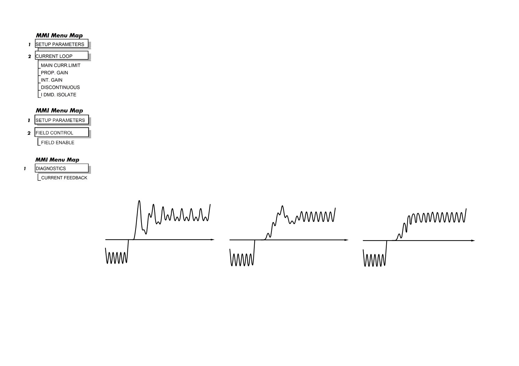
8
8
9
Current Loop controls incorrectly set.
Current Loop controls incorrectly set.
Current Loop controls correctly set.
Rapid alternating oscillation = P gain
Slower oscillatory response = I gain
too high
too high