Hyundai Excavator R210LC-7. Service and repair manual - page 38
8-133
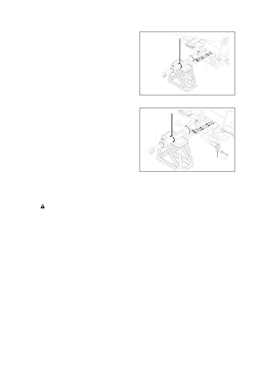
7
8
9
6
Install
Carry out installation in the reverse order
to removal.
When aligning the mounting position of
the pin, do not insert your fingers in the
pin hole.
Bleed the air from the boom cylinder.
Conformed the hydraulic oil level and
check the hydraulic oil leak or not.
(2)
Remove bolt(9) and pull out pin(8).
Remove boom cylinder assembly(6).
Weight : 182kg(386lb)
Disconnect boom cylinder hoses(7) and
put plugs on cylinder pipe.