Hyundai Excavator R210LC-7. Service and repair manual - page 17


  Index      Manuals     Hyundai Excavator R210LC-7. Service and repair manual


Search            copyright infringement  


Content      ..     15      16      17      18     ..


Hyundai Excavator R210LC-7. Service and repair manual - page 17


5 - 24

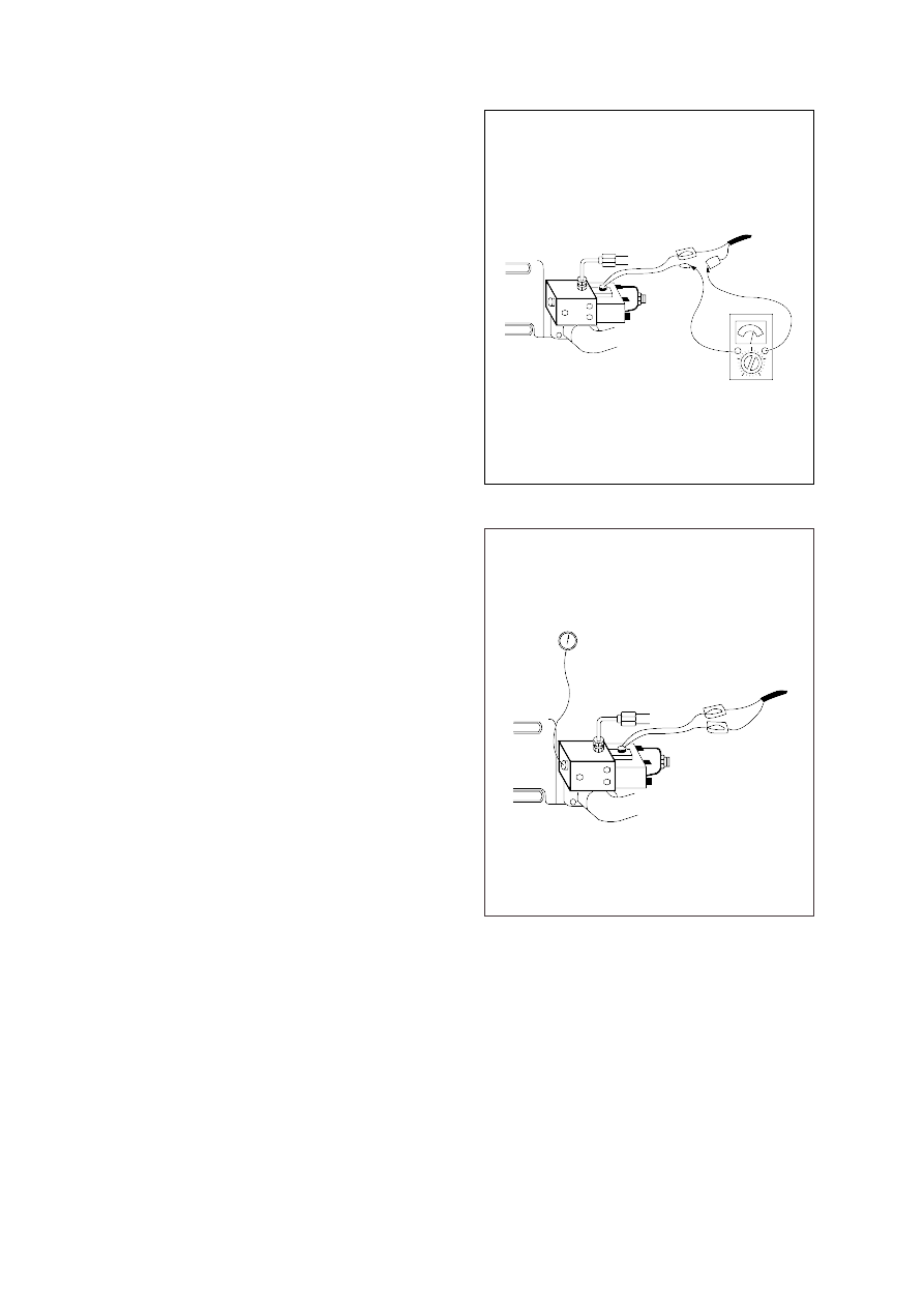
3.  EPPR VALVE CHECK PROCEDURE

CHECK ELECTRIC VALUE AT EPPR VALVE

Start engine.

Set S-mode and cancel auto decel mode.

Position the accel dial at 10.

If tachometer show approx 2150 50rpm,
2050 50rpm(TIER II) disconnect one
wire harness from EPPR  valve.

Install multimeter as figure.

Check electric current at bucket circuit
relief position.

CHECK PRESSURE AT EPPR VALVE

Remove plug and connect pressure
gauge as figure.

Gauge capacity : 0 to 40-50kgf/cm

2

(0 to 580-725psi)

Start engine.

Set S-mode and cancel auto decel mode.

Position the accel dial at 10.

If tachometer show approx 2150 50rpm,
2050 50rpm(TIER II) check pressure at 
relief position of bucket circuit by 
operating bucket control lever.

If pressure is not correct, adjust it.

After adjust, test the machine.

(1)

(2)

(3)

(4)

(5)

(6)

(1)

(2)

(3)

(4)

(5)

(6)

(7)

1)

2)

Spec : 200~450mA

Spec : 2~25kgf/cm

2

(30~350psi)

5-23(1) (290-7)

5-23(2) (290-7)

5 - 25

GROUP  12  PROLIX SWITCH (up to # 0179)

NORMAL POSITION 

EPPR valve supply specified amount of pilot pressure to the flow regulator of hydraulic pump and
regulate hydraulic pump delivery amount depending upon the signal of CPU controller by selected
mode.

EMERGENCY POSITION

If prolix switch is set at the emergency position when any abnormality occurs in NEW CAPO
system, constant electric current from battery flows to EPPR valve so that EPPR valve can be
fixed at the  predetermined position.
In this case excavator can be operated at an equivalent performance to S mode.

Is the conversion switch to manual control temporarily when the electronic control system is out of
order, until repair work be done.

1.  OPERATING PRINCIPLE WIRING DIAGRAM

1)

2)

Electric box

Never place this switch in EMERGENCY

position when the CPU is in normal operation.

CN-50

36

28

24

8

CPU CONTROLLER

2

3

1

6

5

4

T

1

3

4

6

2

5

1

2

3

4

5

6

CS-7

PROLIX SW

CN-75

EPPR V/V

CN-47

RESISTOR

CN-51

32

1

2

1

2

EMERGENCY

NORMAL

Normal        :

Emergency :

21075MS18

21075MS19

21075MS17

5 - 26

GROUP  13  MONITORING SYSTEM

1. OUTLINE

Monitoring system consists of the monitor part and switch part.
The monitor part gives warnings when any abnormality occurs in the machine and informs the
condition of the machine.
Various select switches are built into the monitor panel, which act as the control portion of the machine
control system.

2. CLUSTER 

MONITOR PANEL

1) 

21075MS65A

5 - 27

CLUSTER CHECK PROCEDURE

Start key : ON

Check monitor initial 5 seconds

All lamps light up. 
Buzzer sound.

Check monitor after 5 seconds : Indicate cluster version and machine condition

Cluster program version : CL : 1.4           Indicates program version 1.4 for 2 seconds.
Tachometer : 0rpm
Fuel gauge : All light up below appropriate level
Hydraulic temperature : All light up below appropriate level
Engine coolant temperature gauge : All light up below appropriate level
Warning lamp
During start key 

ON

the engine oil pressure lamp and battery charging lamp go on, but it is not

abnormal.
When engine coolant temperature below 30 C, the warming up lamp lights up.

Indicating lamp state

Work mode selection : General work
Power mode selection : S mode
User mode selection : No LED ON
Auto decel LED : ON
Travel speed pilot lamp : Low(Turttle)

Start of engine

Check machine condition

Tachometer indicates at present rpm
Gauge and warning lamp : Indicate at present condition.
When normal condition : All warning lamp OFF
Work mode selection : General work
Power mode selection : S mode
User mode selection : No LED ON
Auto decel LED : ON
Travel speed pilot lamp : Low(Turttle)

When warming up operation

Warming up lamp : ON
10 seconds after engine started, engine speed increases to1200rpm(Auto decel LED : ON)
Others same as above 

When abnormal condition

The lamp lights up and the buzzer sounds.
If

BUZZER STOP

switch is pressed, buzzer sound is canceled but the lamp light up until normal

condition. 

2) 

(1)

a.
b.

a.
b.
c.
d.
e.
f.

(2)

a.
b.

c.
d.
e.
f.
g.

a.
b.

a.
b.

a.
b.
c.
d.
e.

5 - 28

3. CLUSTER CONNECTOR

No.

Signal

Cluster

Input / Output

Power IG(24V)

GND

Serial-(RX)

Serial+(TX)

Input(20~32V)

Input(0V)

Input(Vpp=12V)

Output(Vpp=4V)

21075MS16

5 - 29

This displays the current time and machine information such as
engine rpm, coolant/hydraulic oil temperature, hydraulic oil
pressure and also error codes.
Refer to the page 5-34 for details.

(1)

This gauge indicates the amount of fuel in the fuel tank.

Fill the fuel when the white range or warning lamp         blinks.

If the gauge illuminates the white range or warning lamp
blinks even though the machine is on the normal condition,
check the electric device as that can be caused by the
poor connection of electricity or sensor.

White range

FUEL GAUGE

This indicates the temperature of coolant.

White range :  Below 30 C(86 F)  
Green range :  30-105 C(86-221 F)
Red range

:  Above 105 C(221 F) 

The green range illuminates when operating.

Keep idling engine at low speed until the green range
illuminates before operation of machine.

When the red range illuminates, reduce the load on the system.
If the gauge stays in the red range, stop the machine and
check the cause of the problem.

Red range

HYDRAULIC OIL TEMPERATURE GAUGE

Red range

ENGINE COOLANT TEMPERATURE GAUGE

(1)

(2)

(1)

(2)

(3)

(4)

This indicates the temperature of coolant.

White range :  Below 30 C(86 F)
Green range :  30-105 C(86-221 F)
Red range

:  Above 105 C(221 F) 

The green range illuminates when operating.

Keep idling engine at low speed until the green range
illuminates before operation of machine.

When the red range illuminates, turn OFF the engine, check
the radiator and engine.

(1)

(2)

(3)

(4)

21073CD04

21073CD05

21073CD05

2)

3)

4)

4. CLUSTER FUNCTION

MONITORING DISPLAY

1)

14073CD03

5 - 30

This lamp blinks and the buzzer sounds when the level of fuel
is below 31 (8.2U.S. gal).

Fill the fuel immediately when the lamp blinks.

FUEL LOW LEVEL WARNING LAMP

(1)

(2)

5)

This lamp blinks and the buzzer sounds when the temperature
of coolant is over the normal temperature 110 C 230 F) .

Check the cooling system when the lamp blinks.

HYDRAULIC OIL TEMPERATURE WARNING LAMP

(1)

(2)

6)

This warning lamp operates and the buzzer sounds when the
temperature of hydraulic oil is over 105 C 221 F).

Check the hydraulic oil level when the lamp blinks.

Check for debris between oil cooler and radiator.

OVERHEAT WARNING LAMP

(1)

(2)

(3)

7)

This lamp blinks and the buzzer sounds after starting the
engine because of pressure.

If the lamp blinks during engine operation, shut OFF engine
immediately.  Check oil level.

ENGINE OIL PRESSURE WARNING LAMP

(1)

(2)

8)

This lamp is operated by the vacuum caused inside when the
filter of air cleaner is clogged which supply air to the engine.

Check the filter and clean or replace it when the lamp blinks.

AIR CLEANER WARNING LAMP

(1)

(2)

9)

21073CD04A

21073CD05A

21073CD06A

21073CD07

21073CD08

5 - 31

This lamp blinks and the buzzer sounds when the coolant is
below LOW in the reservoir tank of radiator.

Check the reservoir tank when the lamp blinks.

COOLANT LEVEL WARNING LAMP

(1)

(2)

10)

Communication problem with CPU controller makes the lamp
blinks and the buzzer sounds.

Check if any fuse for CPU burnt off.

If not check the communication line between them.

(1)

(2)

(3)

CPU CONTROLLER CHECK WARMING LAMP

11)

This lamp blinks and the buzzer sounds when the starting
switch is ON, it is turned OFF after starting the engine.

Check the battery charging circuit when this lamp blinks during
engine operation.

BATTERY CHARGING WARNING LAMP

(1)

(2)

12)

When the machine is overload, the overload warning lamp
blinks during the overload switch ON.

(1)

OVERLOAD WARNING LAMP

13)

The lamp will be ON when pushing power max switch on the
LH RCV lever.

(1)

POWER MAX PILOT LAMP

14)

21073CD09

21073CD10

21073CD13

21073CD15

21073CD11

5 - 32

Operating auto decel or one touch decel makes the lamp ON.

The lamp will be ON when pushing one touch decel switch on
the LH RCV lever.

(1)

(2)

DECEL PILOT LAMP

15)

This lamp is turned ON when the coolant temperature is below
30 C 86 F).

The automatic warming up is cancelled when the engine
coolant temperature is above 30 C, or when 10 minutes have
passed since starting.

WARMING UP PILOT LAMP

(1)

(2)

16)

Turning the start key switch ON position starts preheating in
cold weather.

Start the engine as this lamp is OFF.

PREHEAT PILOT LAMP

(1)

(2)

17)

This switch is to select the machine operation mode, which
shifts from general operation mode to heavy operation mode
and breaker mode in a raw by pressing the switch.

: Heavy duty work mode
: General work mode
: Breaker operation mode

Refer to the page 5-4 for details.

WORK MODE SWITCH

(1)

18)

USER MODE SWITCH

19)

This switch is to select the memory sets, at which you can
change the engine and pump power and memorize it into MI
and MII mode for your preference.

Refer to the page 5-5 for details.

(1)

21073CD17

21073CD18

21073CD12

21073CD20

21073CD21

5 - 33

AUTO DECELERATION SWITCH

20)

The lamp of selected mode is turned ON by pressing the
switch(         ).

H : High power work.
S : Standard power work.

POWER MODE SWITCH

(1)

21)

This  switch is to control the travel speed which is changed to
high speed(Rabbit mark) by pressing the switch and low
speed(Turtle mark) by pressing it again.

TRAVEL SPEED CONTROL SWITCH

(1)

22)

When the starting switch is turned ON first, normally the alarm
buzzer sounds for 2 seconds during lamp check operation.

The red lamp lights ON and the buzzer sounds when the
machine has a problem.
In this case, press this switch and buzzer stops, but the red
lamp lights until the problem is cleared.

BUZZER STOP SWITCH

(1)

(2)

23)

This switch is used to actuate or cancel the auto deceleration
function. 
When the switch actuated and all control levers and pedals are
at neutral position.  Engine speed will be lowered automatically
to save fuel consumption.

Light ON   : Auto deceleration function is selected.
Light OFF : Auto deceleration function is cancelled so that the

engine speed increased to previous setting value.

Operating the auto deceleration function makes the decel
indicating lamp on the LCD panel ON.

(1)

(2)

21073CD22

21073CD23

21073CD24

21073CD25

5 - 34

This switch is used to select the monitor display function.

Refer to the page 5-35 for details.

If the switch is pressed for 3 seconds in time display mode, it is
selected time adjusting function, as below.

Hour by auto decel(         )switch
Minute by buzzer stop(          ) switch.

After time set, the switch is pressed, it returns to clock display.

SELECT SWITCH

(1)

(2)

(3)

24)

21073CD25A

5 - 35

5. MONITORING DISPLAY

OUTLINE

Information of machine performance as monitored by the CPU controller can be displayed on the
cluster when the operator selects a display mode by touching 

SELECT

switch alone or with 

BUZZER

STOP

switch on the cluster as below.

1)

Way 1
Key switch

ON

or 

START

Way 2
Touch 

AUTO DECEL

switch while pressing

BUZZER STOP

at

group 1~4.

Group 0

(Default)

Group 1

(Volt, temp,

EPPR press,

version)

Group 2

(Error code)

Touch 

SELECT

switch

once

while pressing

BUZZER STOP.

In this group 

SELECT

LED 

ON

Touch 

SELECT

switch

twice

while pressing

BUZZER STOP.

In this group 

BUZZER

STOP

LED blinks

How to select display mode

Group selection

Display mode selection

Name

Display group

Display on the cluster

Group 3

(Switch input)

Touch 

SELECT

switch

3 times

while pressing

BUZZER STOP.

In this group 

SELECT

LED blinks at 0.5sec
interval

or

or

or

or

or

or

or

Initial

Touch 

SELECT

1 time

Touch 

SECLET

2 times

Touch 

SELECT 

3 times

Option
(Only when
a pressure
sensor is
installed)

Default

Touch 

SELECT

1 time

Touch 

SELECT

2 times

Touch 

SELECT

3 times

Touch 

SELECT

4 times

Default

Touch 

SELECT

1 time

Press down(     ) & 

SELECT 

at the same time

Default

Touch 

SELECT

1 time

Touch 

SELECT

2 times

Touch 

SELECT

3 times

Touch 

SELECT

4 times

Touch 

SELECT

5 times

Touch 

SELECT

6 times

Touch 

SELECT

4 times

Touch 

SELECT

5 times
Touch 

SELECT

6 times

Engine rpm

Time

Power shift pressure
(EPPR valve)

CPU model & version

Front pump pressure

Rear pump pressure

Pilot pressure

Battery voltage(V)

Potentiometer voltage(V)

Accel dial voltage(V)

Hydraulic oil
temperature( C)

Coolant temperature( C)

Current error

Recorded error
(Only key switch ON)
Recorded error deletion
(Only key switch ON)

Pump prolix switch

Auto decel pressure switch

Power boost switch

Travel oil pressure switch

One touch decel switch

Travel alarm switch

Preheat switch

5 - 36

or

or

or

or

or

or

or

or

Group 4

(Output)

Touch 

SELECT

switch

4 times

while pressing

BUZZER STOP.

In this group 

SELECT

LED blinks at 1sec
interval

How to select display mode

Group selection

Display mode selection

Name

Display group

Display on the cluster

Hourmeter

Neutral relay
(Anti-restart relay)

Travel speed solenoid

Power boost solenoid
(2-stage relief solenoid)

Boom priority solenoid

Travel alarm

Max flow cut off solenoid

Preheat relay

Default

Touch 

SELECT

1 time

Touch 

SELECT

2 times

Touch 

SELECT

3 times

Touch 

SELECT

4 times

Touch 

SELECT

5 times

Touch 

SELECT

6 times

Touch 

SELECT

7 times

By touching 

SELECT

switch once while pressing 

BUZZER STOP

, display group shifts.

Example : Group 0         1         2         3         4         0

5 - 37

DESCRIPTION OF MONITORING DISPLAY

2)

Group

Display

Name

Description

2250 rpm

TIME 12 : 30

EP : 10bar

21 : C1.4

*21 : C5.0

P1 : 100bar

(Option)

P2 : 200bar

(Option)

P3 : 30bar

(Option)

b : 24.8V

Po : 2.5V

dL : 3.8V

Hd : 50 C

Ct : 85 C

It displays current engine speed detected by engine speed
sensor from 500 to 3000rpm.
Range : 500~3000rpm by 10rpm

It displays current time(12 is hour and 30 is minute)
Range : Hour(1~12), minute(00~59)

It shows that pump power shift pressure of EPPR valve being
controlled by the CPU controller is 10bar. 
Range : 00~50bar by 1bar

It shows that machine model(R210LC-7) and the program
version of the CPU controller is 1.4.
Version display range : 0.0~9.9 by 0.1

It displays front pump pressure of 100bar which is detected by
pressure sensor.
Range : 000~500bar by 10bar

It displays rear pump pressure of 200bar which is detected by
pressure sensor. 
Range : 000~500bar by 10bar

It displays pilot pump pressure of 30bar which is detected by
pressure sensor.
Range : 00~50bar by 1bar

It shows that battery power of 24.8V is supplied into CPU controller.
Range : 00.0~48.0V by 0.1V

It shows that potentiometer signal voltage is 2.5V.
Range : 0.0~5.0V by 0.1V

It shows that accel dial signal voltage is 3.8V.
Range : 0.0~5.0V by 0.1V

It shows that hydraulic oil temperature detected by temperature
sensor is 50 C.
Range : 0~150 C by 1 C

It shows that coolant oil temperature detected by temperature
sensor is 50 C.
Range : 0~150 C by 1 C

Engine speed

Time

Power shift 
pressure of
EPPR valve

Model and CPU
program version

Front pump
pressure

Rear pump 
pressure

Pilot pump 
pressure

Battery voltage

Potentiometer 
voltage

Accel dial
voltage

Hydraulic oil 
temperature

Coolant
temperature

Group 1

Group 0

* : TIER II Only

5 - 38

Group

Display

Name

Description

CHECK

Er : 03

TIME

Er : 03

TIME

Er : 00

PP : on 

or

oFF

dP : on 

or

oFF

Pb : on 

or

oFF

oP : on 

or

oFF

od : on 

or

oFF

br : on 

or

oFF

PH : on 

or

oFF

It shows that current error of 03(Short circuit in pump EPPR valve
system) is diagnosed by self diagnosis system in the CPU controller.
If more than 2 errors, when pressing       or       switch, other
error codes show.
Range : 00~58

It shows recorded error code of 03 which is diagnosed before.    
If more than 2 error codes, when pressing       or       switch,
other error codes show.
Range : 00~58

It shows all recorded error codes are removed in the CPU
controller memory.

Current error 

Recorded error

Recorded error
deletion

Pump prolix
switch

Auto decel 
pressure switch

Power 
boost switch

Travel oil
pressure switch

One touch
decel switch

Travel alarm
switch

Preheat switch

Group 3

Group 2

Shows that pump prolix switch is turned on(At
emergency position).
Shows that pump prolix switch is turned off(At normal
position).

Shows that auto decel pressure switch is pressed on
(No operation of control lever).
Shows that auto decel pressure switch is released off
(Operation of control lever).

Shows that power boost switch is pressed on
(Activated).
Shows that power boost switch is released off
(Canceled). 

Shows that travel oil pressure switch is pressed on
(No operation of travel control lever).
Shows that travel oil pressure switch is released off
(Operation of travel control lever).

Shows that one touch decel switch is pressed.
Shows that one touch decel switch is released.

Shows that travel alarm function is selected.
Shows that travel alarm function is canceled.

Shows that preheat switch is pressed.
Shows that preheat switch is released.

PP : on

PP : oFF

dP : on

dP : oFF

Pb : on

Pb : oFF

oP : on

oP : oFF

od : on
od : oFF

br : on
br : oFF

PH : on
PH : oFF

5 - 39

Group

Display

Name

Description

Ho : on 

or

oFF

nr : on 

or

oFF

ts : on 

or

oFF

PS : on 

or

oFF

bs : on 

or

oFF

Ru : on 

or

oFF

FS : on 

or

oFF

PR : on 

or

oFF

Shows that hourmeter is activated by CPU controller.
Shows that hourmeter is turned off. 

Shows that neutral relay for anti-restarting function is
activated(Engine start is possible).
Shows that neutral relay is turned off to disable the
engine restart. 

Shows that travel speed solenoid is activated
(High speed).
Shows that travel speed solenoid is released
(Low speed).

Shows that power boost solenoid is activated to
maximize the power(Power up).
Shows that power boost solenoid is turned off(Cancel
the power boost function).

Shows that boom priority solenoid is activated.
Shows that boom priority solenoid is released.

Shows that travel buzzer is activated.
Shows that travel buzzer is canceled.

Shows that max flow cut off solenoid is activated.
Shows that max flow cut off solenoid is released.

Shows that preheat relay is activated.
Shows that preheat relay is released.

Hourmeter

Neutral relay
(Anti-restart
relay)

Travel speed
solenoid

Power boost
solenoid

Boom priority
solenoid

Travel alarm

Max flow cut off
solenoid

Preheat relay

Group 4

Ho : on
Ho : oFF

nr : on

nr : oFF

ts : on

ts : oFF

PS : on

PS : oFF

bs : on
bs : oFF

Ru : on
Ru :oFF

FS : on
FS : oFF

PR : on
PR : oFF


Content      ..     15      16      17      18     ..