Hyundai Excavator R210LC-7. Service and repair manual - page 8


  Index      Manuals     Hyundai Excavator R210LC-7. Service and repair manual


Search            copyright infringement  


Content      ..     6      7      8      9     ..


Hyundai Excavator R210LC-7. Service and repair manual - page 8


2-64

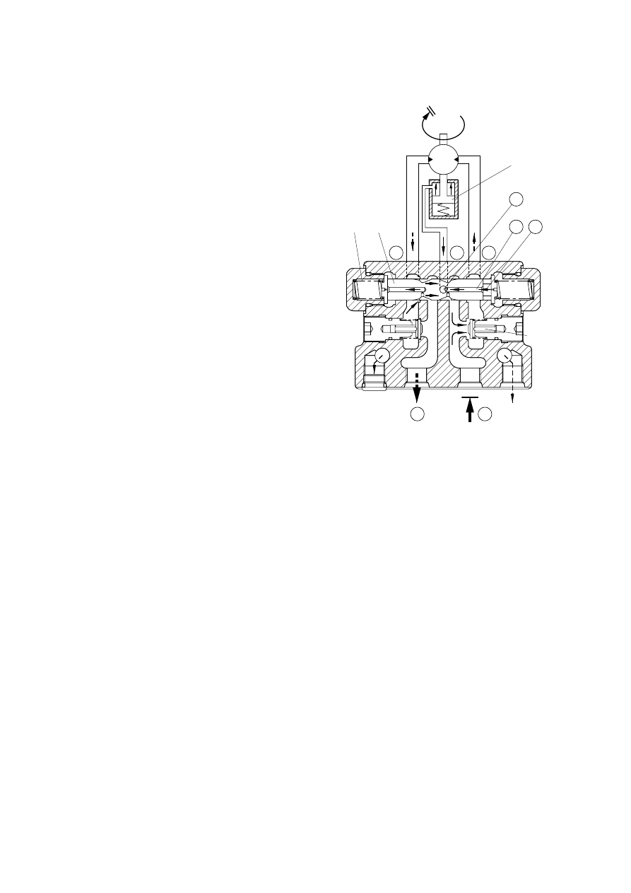
Braking effect on downhill travel

If the machine traveling downhill with a
relatively small supply of high pressure oil
to its travel motors should start coasting,
the same braking effect as the one
described above would automatically
occur.
In the coasting condition, the motor is
driven, instead of driving the track, from
the ground and sucks high pressure oil
in.
In other words, the motor tends to draw
more high pressure oil than is being
supplied.
Under this condition, port A goes
negative to pull oil out of chamber 
through oil way 

, moving back the

spool(323) rather rapidly.
The clearance on the left then becomes
smaller to throttle the outgoing oil more
than before, thereby obstructing the
pumping action of the motor.
As in stopping the machine, pressure will
build up in port D to make it harder to
drive the motor from the ground:   This is
the braking action.

C

E

323

328

D

a

b

327

B

A

Drain

P

112

2-65

Parking brake

Running

When the pressurized oil is supplied from
the brake valve, the spool of brake valve
in the hydraulic motor assembly actuates
to open the passage to the parking brake
and the pressurized oil is introduced into
cylinder chamber 

which is composed

of the spindle of reduction gear assembly
and piston(112).   When the hydraulic
pressure reaches 6kgf/cm

2

(0.59Mpa) or

more, it overcomes the force of spring
(113) and shifts piston(112).   With shift of
piston(112), no pressing force is applied
to mating plate(116) and friction plate
(115) and the movement of friction plate
(115) becomes free, whereby the brake
force to the cylinder in the hydraulic motor
assembly is released.

104

115

116

a

112

113

(3)

Stopping

When the pressurized oil from the brake
valve is shut off and the pressure in
cylinder chamber 

drops 6kgf/cm

2

(0.59Mpa) or less, piston(112) will return
by the force of spring(113).
Piston(112) is pushed by this force of
spring(113), and mating plate(116) and
friction plate(115) in free condition are
pressed against the spindle of reduction
gear assembly.
The friction force produced by this
pressing stops rotation of the cylinder
block(104) and gives a braking torque
40.6kgf

m(398N m) to the hydraulic

motor shaft.
Note that oil control through a proper oil
passage ensures smooth operation.

104

115

116

a

112

113

2-66

High/low speed changeover mechanism

At low speed

- At pilot pressure of less than 20kgf/cm

2

(1.96Mpa)

(4)

a

θ

1

A

B

C

P

366

363

103

161

Spindle

Support

Motor

case

Drain

Pilot pressure

a

b

θ

2

A

B

C

P

366

363

103

161

Spindle

Support

Motor

case

Drain

Pilot pressure

When a pilot pressure supplied from port  (At a pressure of 20kgf/cm

2

(1.96Mpa) or more), the

pressure overcomes the force of spring(366) and valve(363) is pressed downward.   The
pressurized oil supply port 

is then introduced into chamber 

through the valve(363).   Piston

(161) pushes up swash plate(103) until it touches side 

of the spindle.   At this time, swash

plate(103) is tilted at a minimum angle(

2

) and the piston displacement of hydraulic motor

becomes minimum, thus leading to high-speed operation.

When the pilot pressure is shut off from port  , valve(363) is pressed upward by the force of
spring(366), the pressurized oil supply port 

is shut off, and oil in chamber 

is released into

the motor case through the valve(363).   Consequently, swash plate(103) is tilted at a maximum
angle(

1

) and the piston displacement of hydraulic motor becomes maximum, thus leading to

low-speed operation.

At high speed

- At pilot pressure of 20kgf/cm

2

(1.96Mpa) or more 

2-67

REDUCTION GEAR

Function

This reduction gear is composed of spur
reduction gears(First reduction) and
differential reduction gears(Second
reduction).   It decrease high rotating
speed, increase output torque of a
hydraulic motor and rotates a gear case.

Operating principle

First reduction

At the right figure, the rotating motion of
hydraulic motor is transmitted to the input
gear(6) of first reduction.   Then three
spur gears(7) engaged with the input
gear(6) rotate with reducing the rotating
speed.   Gear ratio of first reduction is
described as the following.

Zi

i1 = -

Zs

Zi  : Number of input gear teeth
Zs : Number of spur gear teeth

2)

Crank shaft

Shaft

Input gear

Spur gear

(1)

(2)

Second reduction

Three spur gears(7) are connected
severally to the three crank shafts(9).
These crank shafts(9) are input of second
reduction.

Planetary gear mechanism

Crank shaft

Spur gear

Rotation

Rotation

Eccentric

Needle bearing

Eccentric motion

RV gear A

RV gear B

A

B

Differential gear mechanism

2-68

RV gears(4), (5) are fitted up the
eccentric crank shaft(9) through bearings.
According to rotating of the crank
shafts(9), RV gears(4), (5) revolve
(Eccentric motion) along pin-gears(17)
within hub(1).   As these crank shafts are
supported by spindle(2), hub (1) rotates
with reducing the speed.   Gear ratio of
second reduction is described as the
following.

(Zp - ZR)

i2 = 

Zp

Zp : Number of pin
ZR : Number of RV gear teeth

Total gear ratio of this reduction gear is
described as the following.

Zi        (Zp-ZR)

i = i1 i2 = -        

Zs            Zp 

360

2 x 24

4

3

RV gear A or B

22

23

24 1 2

3

4

Crank shaft

Pin

Hub

1

2

3

22

23 24

1 2

5

4

3

22

23

24 1

2

360

24

Crank shaft

half revolution 

Crank shaft

one revolution 

Combination of planetary gear mechanism
and differential gear mechanism

2-68-1

B. TRAVEL DEVICE(SBTR220, #2079 and up)

1.  STRUCTURE

hydraulic motor includes five followings.

·

Part of rotary generating turning force

·

Part of a valve of relief

·

Part of Brake

·

Part of a valve of counterbalance

·

Part of plowing changeover

·

Part of auto changeover

A

T1

T2

P1

P2

Pm1

Pm2

Ps

21078TM12

Ps

T1.T2

P2

P1

Pm2

Pm1

21078TM04

Port

P

1

, P

2

P

2

, P

1

Pm

1

, Pm

2

T

1

, T

2

Ps

Port name

Main port(IN)

Main port(OUT)

Gauge port

Prain port

2 speed 

control port

SAE 4694psi

SAE 4694ps

PF 1/4

PF 1/2

PF 1/4

Port size

2-68-2

2.  PRINCIPLE OF DRIVING

2.1 Generating the turning force

The high hydraulic supplied from a hydraulic pump flows into a cylinder(10) through valve casing of
motor(29), and valve plate(77).
The high hydraulic is built as flowing on one side of Y-Y line connected by the upper and lower sides of
piston(18).
The high hydraulic can generate the force, F1 = P

×

A(P : Supplied pressure, A : water pressure area),

like following pictures, working on a piston.
This force, F1, is divided as N1 thrust partial pressure and W1 radial partial pressure, in case of the
plate(09) of a tilt angle, 

α

.

W1 generates torque, T = W1+R1, for Y-Y line connected by the upper and lower sides of piston as
following pictures.
The sum of torque(

Σ

W1

×

R1), generated from each piston(4~5pieces) on the side of a high

hydraulic, generates the turning force.
This torque transfers the turning force to a cylinder(10) through a piston; because a cylinder is
combined with a turning axis and spline, a turning axis rotates and a turning force is sent.

F1

f1

N1

W1

Y

Y

R1

P

A

O

W1

Cylinder

Low
pressure

High
pressure

Pistion

21078TM05

2-68-3

2.2 Working of relief valve

Relief valve carries on two functions of followings.

It standardizes a pressure in case of driving a hydraulic motor ; bypasses and extra oil in a motor
inlet related to acceleration of an inertia to an outlet.

In case of an inertia stopped, it forces an equipment stopped, according to generating the pressure
of a brake on the projected side.
Room A is always connected with port A of a motor.  If the pressure of port is increased, press
poppet A.  And if it is higher than the setting pressure of a spring, the oil of an hydraulic flows from
room A to port B, because poppet A is detached from the contact surface of seat A.

1)

2)

Chamber A

Port A

Port B

Poppet A

21078TM06

2-68-4

2.3 Working of negative brake

Negative brake operates the pressure supplied through SPOOL(simultaneous peripheral operation
online) installed in valve casing(29) to the part of brake piston(21) and releases a brake.  
When the pressure does not work, the brake always runs.
The force of a brake is generated by the frictional force among a plate(20) fixed by shaft casing, brake
piston(21) and a frictional plate(19) connected through spline outside a cylinder(10).
When a pressure does not work on the part of piston, brake spring presses brake piston; oil in a brake
room flows into the drain of a motor through an orifice; in that time, brake piston compresses a
frictional plate and a detached plate in the middle of shaft casing and brake piston according to the
force that presses 10 pieces of brake springs(68, 67); finally, it makes a frictional force.
This frictional force helps the brake fixing a turning axis(06) connected by a cylinder and spline
operated.

67

65

68

1

6

21

19

20

10

21078TM07

2-68-5

2.4 Counterbalance valve

Av port is connected into a hydraulic pump; Bv port is into a tank.

An oil supplied to a hydraulic pump presses check valve on Av 

Cv; through L port, is provided to a

hydraulic motor.  It makes a hydraulic motor circulated.  However, the oil pressure out of a pump is
increased and transferred to spring room, M, through the path, G, because negative brake is working
on.  If the pressure of room M is over the power of spring that keeps spool medium, spool moves to
the right side.
An oil in room N is sent to room M by orifice I and discharged from G line to a tank.
So spool moves to the right.  The oil flows as the way of K 

Bv.

Av

Bv

Cv

Dv

N

M

I

G

L

K

21078TM08

2-68-6

2.5 Working description of automatic switch(at normal speed)

Due to no pressure on pilot now, spool(47) is not working.

2 Speed line

2 Speed 
changeover
pressure port

2 Speed line

Av

Bv

D

D1

47

(Normal Speed)

21078TM09

2-68-7

2.6 Working description of automatic switch(at high speed)

At normal speed, once the hydraulic oil which is through the inner path of spool(47) flows into high
speed switching pressure port(The pressure of external pilot : Pi = 35kgf/cm

2

) spool(47) moves from

right to left.
At high speed, turning pressure of motor(D1) is over 250kgf/cm

2

, when the power forcing to spool(59)

(Pressure, P1) is stronger than spool(47) and spool(59) is pushed out, after then spool(47) moves
from left to right.  So it is switched.

2 Speed line

2 Speed 
changeover
pressure port

2 Speed line

Av

Bv

D

D1

47

(High Speed)

59

21078TM10

2-69

1. STRUCTURE

The casing has the oil inlet port P(Primary pressure) and the oil outlet port T(Tank).   In addition the
secondary pressure is taken out through ports 1,2,3 and 4 provided at the bottom face.

GROUP  5    RCV LEVER

23.3

A

30

19

25

Handle bending direction

Single

operation

Simultaneous

operation

(No. push rod direction)

4

P

3

2

T

1

30

VIEW A

T
P

1

3 2

4

Hydraulic circuit

Port

LH

RH

Port size

Pilot oil inlet port

Pilot oil return port

Bucket out port

Boom down port

Bucket in port

Boom up port

PF 1/4

Pilot oil inlet port

Pilot oil return port

Left swing port

Arm in port

Right swing port

Arm out port

P

T

1

2

3

4

2-70

CROSS SECTION

The construction of the pilot valve is shown in the attached cross section drawing.   The casing has
vertical holes in which reducing valves are assembled.
The pressure reducing section is composed of the spool(5), spring(7) for setting secondary pressure,
return spring(10), stopper(9), spring seat(8) and shim(6).   The spring for setting the secondary
pressure has been generally so preset that the secondary pressure is 5 to 20.5kgf/cm

2

(Depending on

the type).   The spool is pushed against the push rod(14) by the return spring.
When the push rod is pushed down by tilting the handle, the spring seat comes down simultaneously
and changes setting of the secondary pressure spring.

1

Case

2

Plug

3

Plug

4

O-ring

5

Spool

6

Shim

7

Spring

8

Spring seat

9

Stopper

10

Spring

11

Plug

12

Rod seal

13

O-ring

14

Push rod

15

Plate

16

Bushing

17

Joint assembly

18

Swash plate

19

Adjusting nut

20

Lock nut

21

O-ring

22

Handle connector

23

Nut

24

Insert

25

Boot

26

Handle

27

Switch assembly

28

Screw

29

Switch assembly

30

Switch cover

40

Boot

2-71

CROSS SECTION

14072SF80

2-72

2. FUNCTIONS

FUNDAMENTAL FUNCTIONS

The pilot valve is a valve that controls the spool stroke, direction, etc of a main control valve.   This
function is carried out by providing the spring at one end of the main control valve spool and
applying the output pressure(Secondary pressure) of the pilot valve to the other end.
For this function to be carried out satisfactorily, the pilot valve is composed of the following
elements.

Inlet port(P) where oil is supplied from hydraulic pump.

Output ports(1,2,3 & 4) to apply pressure supplied from inlet port to ends of control valve spools.

Tank port(T) necessary to control the above output pressure.

Spool to connect output port to inlet port or tank port.

Mechanical means to control output pressure, including springs that work on the above spools.

FUNCTIONS OF MAJOR SECTIONS

The functions of the spool(5) are to receive the supply oil pressure from the hydraulic pump at its
port P, and to change over oil paths to determine whether the pressure oil of port P is led to output
ports 1,2,3 & 4 or the output port pressure oil to tank port T.
The spring(7) works on this spool to determine the output pressure.
The change the deflection of this spring, the push rod(14) is inserted and can slide in the plug(11).
For the purpose of changing the displacement of the push rod through the switch plate(19) and
adjusting nut(20) are provided the handle(27) that can be tilted in any direction around the fulcrum
of the universal joint(18) center.
The spring(10) works on the case(1) and spring seat(8) and tries to return the push rod(14) to the
zero-displacement position irrespective of the output pressure, securing its resetting to the center
position.
This also has the effect of a reaction spring to give appropriate control feeling to the operator.

1)

(1)

(2)

(3)

(4)

(5)

2)


Content      ..     6      7      8      9     ..