Hyundai Excavator R210LC-7. Service and repair manual - page 7


  Index      Manuals     Hyundai Excavator R210LC-7. Service and repair manual


Search            copyright infringement  


Content      ..     5      6      7      8     ..


Hyundai Excavator R210LC-7. Service and repair manual - page 7


2-57

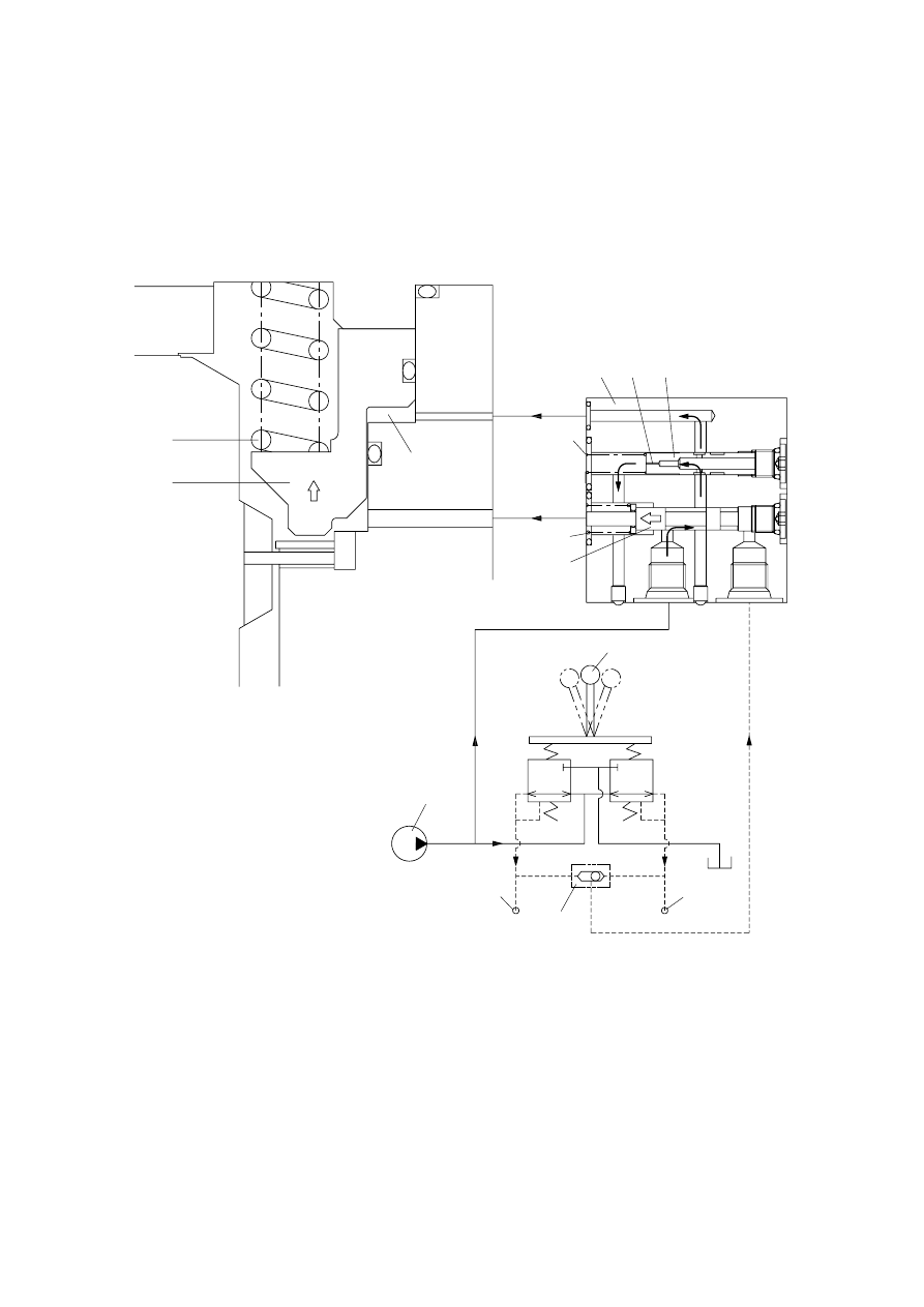
When the swing control(1) lever is set the neutral position, the spool(5) returns right in the time
delay valve(3).
Then, the piston(6) is moved lower by spring force and the return oil from the chamber G flows
back to D-port through orifice(10) of the poppet(7).
At this time, the poppet(7) works to make a time lag for 5 seconds.

1

Swing control lever

2

Swing control valve(MCV)

3

Time delay valve

4

Shuttle valve

5

Spool

6

Piston

7

Poppet

8

Spring

9

Spring

10

Orifice

11

Spring

12

Pilot pump

9

6

G

3

10

7

P

g

11

D

8

5

S

h

1

12

P

3

2

4

2

c.

2-57-1

B. SWING DEVICE(RMF151, #1938 and up)
1. STRUCTURE

Swing device consists swing motor, swing reduction gear.
Swing motor include mechanical parking valve, relief valve, make up valve and time delay valve.

PG

A

B

GA

GB

SH

Dr

A,B

Reduction gear

Swing gear

Gear oil 
drain port

Relief valve

Time delay valve

Mu

Au

GB

SH

PG

Dr

GA

B

Mu

A

Port

A

B

Dr

Mu

PG

SH

GA, GB

Au

Port name

Main port

Main port

Drain port

Make up port

Brake release port

Stand by port

Gage port

Air vent port

Port size

Ø

20

Ø

20

PF 1/2

PF 1

PF 1/4

PF 1/4

PF 1/4

PF 1/4

22007SF03A(1)

2-57-2

SWING MOTOR

1

Body

2

Oil seal

3

Roller bearing

4

Snap ring

5

Shaft

6

Bushing

7

Stop ring

8

Pin

9

Shoe plate

10

Cylinder block

11

Spring

12

Ball guide

13

Set plate

14

Piston assy

15

Friction plate

16

Plate

17

Brake piston

18

O-ring

19

O-ring

20

Spring

21

Rear cover

22

Needle bearing

23

Pin

24

Valve plate

25

O-ring

26

O-ring

27

Wrench bolt

28

Plug

29

Back up ring

30

O-ring

31

Spring

32

Check

33

Relief valve

34

Anti-inversion valve

35

Time delay valve

36

Wrench bolt

37

Plug

38

O-ring

39

Plug

40

Plug

41

Plug

42

Name plate

43

Rivet

44

Level gauge

45

Flange

46

O-ring

47

Plug

48

O-ring

49

O-ring

50

Back up ring

K

4 1

26

9

1316

18 19 24 21 22 42

37

38

45

46

34

32

28

31

30

40

35

36

44

33

41

20

17

10

12

6

3

2

14

15

43

27

7

5

11

8 23

39

29

25

DETAIL :  K

1)

220072SM02

2-57-3

REDUCTION GEAR

1

Casing

2

Drive shaft

3

Spacer

5

Roller bearing

6

Oil seal

7

Roller bearing

8

Thrust plate

9

Carrier 2

10

Stop ring

11

Ring gear

12

Knock pin

13

Pinion gear

14

Thrust washer

15

Planet gear 2

16

Pin 2

17

Spring pin

18

Sun gear 2

19

Carrier 1

20

Side plate 1

21

Pin 1

22

Needle cage

23

Bush 2

24

Planet gear 1

25

Lock washer

26

Side plate 3

27

Sun gear 1

28

Stop ring

29

Plug

30

Plug

31

Socket bolt

34

Cover plate

35

Hexagon bolt

36

Lock plate

37

Hexagon bolt

38

Stop ring

39

Side plate 2

1

2

3

5

6

7

8

9

10

11

12

13

14

15 16

17

18 19

20

21

23

24

25

26

27

28

29

30

31

34

35

36

37

38

39

22

2)

220072SF05A

2-57-4

2. PRINCIPLE OF DRIVING

2.1 Generating the turning force
The high hydraulic supplied from a hydraulic pump flows into a cylinder(10) through valve casing of
motor(21), and valve plate(24).
The high hydraulic is built as flowing on one side of Y-Y line connected by the upper and lower sides of
piston(14).
The high hydraulic can generate the force, F1=P

×

A(P : supplied pressure, A : water pressure area),

like following pictures, working on a piston.
This force, F1, is divided as N1 thrust partial pressure and W1 radial partial pressure, in case of the
plate of a tilt angle, 

α

.

W1 generates torque, T=W1+R1, for Y-Y line connected by the upper and lower sides of the piston as
following pictures.
The sum of torque(

Σ

W1

×

R1), generated from each piston(4~5 pieces) on the side of a high

hydraulic, generates the turning force.
This torque transfers the turning force to a cylinder(10) through a piston; because a cylinder is
combined with a turning axis and spline, a turning axis rotates and a turning force is sent.

F1

f1

N1

W1

Y

Y

R1

P

A

O

W1

Cylinder

Low
pressure

High
pressure

Pistion

21078TM05

2-57-5

2.2 Working of relief valve

Relief valve carries on two functions of followings

It standardizes a pressure in case of driving a hydraulic motor; bypasses an extra oil in a motor inlet
related to acceleration of an inertia to an outlet.

In case of an inertia stopped, it forces an equipment stopped, according to generating the pressure
of a brake on the projected side.

Once high pressure oil supplied to P port, the inside pressure of shock less spool increases.
If the pressure is stronger than the power of the spring, it will be standardized.
In case of driving a hydraulic motor, it standardizes a pressure.  And in the event of stopping an
inertia, it forces an equipment stopped, according to generating the pressure of break on the
projected side.

1)

2)

1

2

3

4

5

6

7

8

9

10

11

12

220072SM10

2-57-6

2.3 Working of parking brake

Parking brake OFF
If swing control level sets the swing position, pilot oil will moves swing spool and also it will be
supplied to SH port of time delay valve of swing motor through shuttle salve against the power of the
spring.  The pressure of the spring switches spool to left and moves awaiting PG port oil of delay
valve to parking position.  After then it moves up parking piston pressing frictional plate to release
parking brake.

Parking brake ON
If swing control level sets neutrality, swing pilot suplied to SH port of time delay valve through shuttle
valve will be stopped.
According to this process, spool is returned by the power of the spring and the pressure of PG port
of time delay valve which is always standing by release valve is stopped to parking piston.
In that time, orifice in spool stops leaking out working  oil to create 6 second time delay in order to
prevent the impact which may be happened at the moment of sudden stop of swing brake.

1)

2)

5

10

17

20

8

23

1

9

16

15

24

220072SM11

2-57-7

2.4 Make up check valve

In case of rapid rotation which is faster than the amount of supplied oil to swing motor entrance,
mounted make up check valve supplies working oil to prevent cavitation according to the shortage of
supplying oil.
In the event of sudden stop of the operating excavator, supplying working oil to entrance of swing
motor is stopped.  However, by means of inertia of rotation, swing motor will be stopped after more
rotation.  In that time, make up check valve is opened and supplies working oil according to the
pressure of hydraulic oil line to the entrance of the motor, which is lower than working oil awaiting in a
make up check valve port.

1

2

3

4

5

6

7

8

9

10

11

12

220072SM10

2-57-8

2.5 Working description of plowing switch

The capacity of driving motor is changeable depending on the change of plowing angle of the plate.
That is operated by a plowing valve.

The pressure of external pilot : when Pi = 0 (large plowing)
A high pressure oil operated at a motor works on port P of a switching valve, by the highpressure
selecting function installed in valve casing.
Spool assembled at the switching part of plowing is adhered to plug by spring.
So the high pressure oil of port P flows to port Sb.
The pressure of this oil can be operated from port Sb to room A, through valve casing and the path
A' of shaft casing.  An oil in room B flows into a drain line through the path of B 

Sa.

Plowing piston moves to the right side because of the high pressure oil; the plate moves to the
place adhered to stopper, based on the shaft "0" ; it is fixed.

Sh

Pg

12

13

10

9

8

2

7

6

1

3

5

4

11

220072SM12

1)

2-57-9

2.6 Working of anti-inversion valve

In the event of swing motor operates switch part to drive and stop the swing part.  By the action of
pump on motor, there is break on both-side of port because of the block on both sides.
Swing part is stopped by pressure of brake(in order words, 4-5 times of inversion)
Under the operating condition, the side of anti-inversion blocks off both ports but bypassing
compressed oil which is blocked in processing of anti-inversion fixed time and amount to inverse port,
prevent increasing pressure of motor and decrease inversing action.

5

1

4

3

2

6

7

220072SM13

2-58

A. TRAVEL DEVICE(GM35VL, up to #2078)

1.  CONSTRUCTION

Travel device consists travel motor and gear box.
Travel motor includes brake valve, parking brake and high/low speed changeover mechanism.

GROUP  4  TRAVEL DEVICE

P

2

Oil fill port(PF 1/2)

Oil level check port(PF 1/2)

Drain port(PF 1/2)

A

B

D

2

D

1

P

1

P

3

2 speed control port(P)

D

2

D

1

P

2

P

1

P

3

P

A B

Pressure gauge port(P

1

~P

2

)

Hi Low

Parking brake release 

gauge port(P

3

)

Port

A

B

P

1

, P

2

P

3

D

1

, D

2

P

Port name

Main port

Main port

Gauge port

Gauge port

Drain port

2 speed control port

Port size

SAE 5000psi 1"

SAE 5000psi 1"

PT 1/4

PT 1/8

PF 1/2

PF 1/4

RED

25032TM01

2-59

BASIC STRUCTURE

1)

Reduction gear

Hydraulic motor

Brake valve

Parking brake

High/low speed

changeover mechanism

Control valve

Hydraulic pump

2-61

2.  FUNCTION

HYDRAULIC MOTOR

Rotary group

1)

P

F

3

103

109

301

104

105

102

F

3

F

2

F

1

F

3

Y

2

F

3

α

Y

1

F

3

ri

P

A

The pressurized oil delivered from the hydraulic pump flows to rear flange(301) of the motor,
passes through the brake valve mechanism, and is introduced into cylinder block(104) via timing
plate(109).   This oil constructively introduced only to one side of Y1-Y2  connecting the upper and
lower dead points of stroke of piston(105).   The pressurized oil fed to one side in cylinder
block(104) pushes each piston(105, four or five) and generates a force(F kg = P kg/cm

2

A cm

2

).   

This force acts on swash plate(103), and is resolves into components (F2 and F3) because swash
plate(103) is fixed at an angle( ) with the axis of drive shaft(102).   Redial component(F3)
generates respective torques(T = F3 ri) for Y1-Y2.     This residual of torque(T = F3 ri) rotates
cylinder block(104) via piston(105).   Cylinder block(104) is spline-coupled with drive shaft(102).
So the drive shaft(102) rotates and the torque is transmitted.

(1)

2-62

Brake valve

Brake released

(Starting / Running)

When the pressurized oil supplied from
port 

, the oil opens valve(327) and

flows into port 

at the suction side of

hydraulic motor to rotate motor.   At the
same time, the pressurized oil passes
through pipe line 

from a small hole in

spool(323) and flows into chamber  .
The oil acts on the end face of spool(323)
which is put in neutral position by the
force of spring(328), thus causing
spool(323) to side to the left.   When
spool(323) slides, port 

on the passage

at the return side of hydraulic motor,
which is closed by the spool groove
during stoppage, connected with port 
at the tank side and the return oil from the
hydraulic motor runs into the tank.   In
consequence, the hydraulic motor
rotates.   Moreover, sliding of spool(323)
causes the pressurized oil to flow into
ports  .
The pressurized oil admitted into port 
activates piston(112) of the parking brake
to release the parking brake force.   (For
details, refer to description of the parking
brake.)   When the pressurized oil is
supplied from port  , spool(323) move
reversely and the hydraulic motor also
rotates reversely.

(2)

C

E

323

328

D

a

b

327

B

A

P

112

Drain

2-63

Brake applied

(Stopping / Stalling)

When the pressurized oil supplied from
port 

is stopped during traveling, no

hydraulic pressure is applied and
spool(323) which has slid to the left will
return on the right(Neutral) via stopper
(325) by the force of spring(328).
At the same time, the hydraulic motor will
rotate by the inertia even if the
pressurized oil stopped, so the port D of
the motor will become high pressure.
This pressurized oil goes from chamber

to chamber 

through the left-hand

valve(201). 
When the oil enters chamber 

, the

piston(381) slids to the right so as not to
rise the pressure, as shown in the figure.
Meanwhile, the left-hand valve(201) is
pushed open by the pressurized oil in
port D.
Therefore, the pressurized oil in port D
flows to port C at a relatively low
pressure, controlling the pressure in port
D and preventing cavitation in port C.
When the piston(381) reaches the stroke
end, the pressure in chamber 

and 

increase and the left-hand valve(201)
closes again, allowing the oil pressure in
port D to increase further.   Then, the
right-hand valve(201) opens port C with
pressure higher than that machine relief
set pressure.
In this way, by controlling the pressure in
port D in two steps, the hydraulic motor is
smoothly braked and brought to a stop.

f

D

C

323

g

B

A

325

328

381

201

327

330


Content      ..     5      6      7      8     ..