EMCO WinNC GE Series Fanuc 21 MB. Software description/ Software version from 13.76 - page 3


  Index      Manuals     EMCO WinNC GE Series Fanuc 21 MB. Software description/ Software version from 13.76


Search            copyright infringement  


Content      ..     1      2      3      4      ..


EMCO WinNC GE Series Fanuc 21 MB. Software description/ Software version from 13.76 - page 3


EMCO W

IN

NC GE S

ERIES

 F

ANUC

 21

MB

P

ROGRAMMING

D 11

G15 End Polar Coordinate

Interpolation

G16 Begin Polar Coordinate

Interpolation

Format

N...  G15/G16
Between G16 and G15 points can be defined by polar

coordinates.

The selection of the plane in which polar coordinates

can be programmed occurs with G17 - G19.

With the address of the first axis the radius will be

programmed, with the address of the second axis the

angle  will  be  programmed,  both  related  to  the

workpiece zero point.

Example

N75 G17 G16

N80 G01 X50 Z30

first axis:

radius

X=50

second axis:

angle

Y=30

EMCO W

IN

NC GE S

ERIES

 F

ANUC

 21

MB

P

ROGRAMMING

D 12

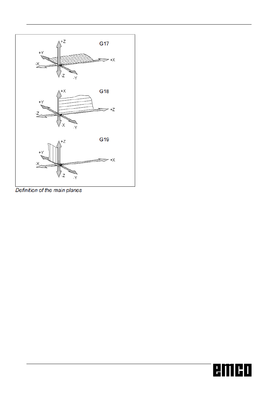
G17-G19  Plane Selection

Format

N...  G17/G18/G19
With G17 to G19 the plane will be defined, in which

circular interpolation and polar coordinate interpolation

can  be  proceeded  and  in  which  the  cutter  radius

compensation will be calculated.

In the vertical axis to the active plane the tool length

compensation will be proceeded.

G17 XY-Plane

G18 ZX-Plane

G19 YZ-Plane

G20 Measuring in Inches

Format

N...  G20
By  programming  G20  the  following  values  will  be

converted to the inch system:

• Feed F [mm/min, inch/min, mm/rev, inch/rev]

• Offset values (WORK, geometry and wear)

[mm, inch]

• Traverse pathes [mm, inch]

• Display of the actual position [mm, inch]

• Cutting speed [m/min, feet/min]

Notes

• For clearness G20 should be programmed in the

first block

• The last active measuring system will be hold -

even with main switch off/on.

• To get back to the origin measuring system it is the

best to use the MDI mode (e.g. MDI-G20-Cycle

Start)

G21Measuring in Millimeter

Format

N...  G21
Comments and notes analogous to G20!

EMCO W

IN

NC GE S

ERIES

 F

ANUC

 21

MB

P

ROGRAMMING

D 13

G28 Approach Reference Point

Format

N...  G28  X...  Y...  Z...
X, Y, Z

Coordinates of the intermediate point.

With G28 the reference point will be approached via

an intermediate position (X, Y, Z).

First  is  the  movement  to  X,  Y  and  Z,  then  the

reference point will be approached. Both movements

occur with G00!
The shift G92 will be deleted.

EMCO W

IN

NC GE S

ERIES

 F

ANUC

 21

MB

P

ROGRAMMING

D 14

Definition ofG42 cutter radius compensation right

Definition ofG41  cutter radius compensation left

Radius compensated tool path

G42 Cutter Radius

Compensation right

If the tool is (viewed in feed direction) at the 

right 

side

of  the  contour  to  be  worked,  G42  has  to  be

programmed.

Notes see G41!

G41Cutter Radius

Compensation left

If the tool is (viewed in feed direction) at the 

left 

side

of  the  contour  to  be  worked,  G41  has  to  be  pro-

grammed.

For calculating a radius, an H parameter in the offset

register (OFFSET) which represents the cutter ra-

dius must be programmed and called up with G41

e.g.:
N...   G41  H..

Notes

• Direct change between G41 and G42 is not allowed

- previous cancellation with G40.

• Selection in combination with G00 or G01 necessary

• Programming  an  H  parameter  is  necessary

unconditionally,  the  H  parameter  is  effective

modally.

Cutter Radius Compensation

With  the  cutter  radius  compensation  the  control

calculates automatically a path parallel to the pro-

grammed contour and compensates so the cutter

radius.

G40 Cancel Cutter Radius

Compensation

The cutter radius compensation will be cancelled by

G40.

Cancellation is only permitted in combination with a

linear traversing movement (G00, G01).

G40 can be programmed in the same block like G00

or G01 or in the previous block.

Usually G40 will be programmed with the retraction to

the tool change point.

EMCO W

IN

NC GE S

ERIES

 F

ANUC

 21

MB

P

ROGRAMMING

D 15

programmed tool path

real traversed tool path

With arcs always the tangent of the end or start point

of the arc will be approached.

If contour elements are smaller than the cutter radius

R,  contour  violations  could  happen.  The  software

computes  three  blocks  forward  to  recognize  this

contour violations and interrupt the program with an

alarm.

Tool pathes with selection / cancellation of the cutter radius compensation

programmed tool path

real traversed tool path

With arcs always the tangent of the end or start point

of the arc will be approached.
The approaching path to the contour and the leaving

path from the contour must be larger than the tool

radius R, otherwise program interruption with alarm.
If contour elements are smaller than the tool radius R,

contour  violations  could  happen.  The  software

computes  three  blocks  forward  to  recognize  this

contour violations and interrupt the program with an

alarm.

Frontal approach or leaving of an edge point

Approach or leaving an edge point at side behind

Approach or leaving an edge point behind

Tool pathes with program run with active cutter radius compensation

Tool path at an inner edge

Tool path at an outer edge > 90°

Tool path at an outer edge < 90°

5

*

*

5

*

*

5

*

*

5

5

5

*

5

*

*

5

*

*

5

5

5

*

5

EMCO W

IN

NC GE S

ERIES

 F

ANUC

 21

MB

P

ROGRAMMING

D 16

G43 Tool Length Compensation

positive

G44 Tool Length Compensation

negative

Format:

N...  G43/G44  H..
With G43 and G44 a value from the offset register

(OFFSET) can be called up and added to or sub-

tracted from as tool length. To all following Z move-

ments (with active XY plane - G17) in the program

this value will be added to or subtracted from.

Example:

N...   G43 H05

The value, which is written into the register under

H05, will be added to all following Z movements as

tool length.

G49 Cancel Tool Length

Compensation

The positive (G43) or negative (G44) shift will be

cancelled.

G50 Cancel Scale Factor, Mirror

G51Scale Factor, Mirror

Format:

N...  G50

N...  G51  X...  Y...  Z...  I...  J...  K...
With  G51  all  position  data  will  be  calculated  in  a

scale, until the scale will be deselected with G50.

With X, Y and Z a base point P

B

 will be defined, from

this point all values will be calculated.

With I, J and K for every axis a scale factor (in 1/1000)

can be defined.

Enlarging a contour 1:2

=

3

%

*;<=,-.

;

<

=

EMCO W

IN

NC GE S

ERIES

 F

ANUC

 21

MB

P

ROGRAMMING

D 17

By programming I-1000 all X positions will be mir-

rored around the YZ plane.

By programming J-1000 all Y positions will be mir-

rored around the ZX plane.

By programming K-1000 all Z positions will be mir-

rored around the XY plane.

Distortion of a contour: X 1:2, Y,Z 1:1

If different scale factors will be defined for the axes,

the contour will be distorted.

Circular movements must not be distorted, otherwise

alarm.

Mirroring a Contour

By programming a negative scale a contour will be

mirrored around the base point P

B

.

3

%

<

;

*;<=,-=

;

<

;

<

;

,

3

%

3

%

;

<

;

<

-

<

3

%

3

%

3

%

;

<

=

;

<

=

.

;

<

=

;

<

=

3

%

EMCO W

IN

NC GE S

ERIES

 F

ANUC

 21

MB

P

ROGRAMMING

D 18

G52 Local Coordinate System

Format:

N...  G52  X...  Y...  Z...
With G52 the actual coordinate zero point can be

shifted for the values X, Y, Z.

With this function a sub coordinate system to the

existing coordinate system can be created.

G52 is effective blockwise, the resulting shift will be

holded, until another shift will be activated.

G53 Machine Coordinate System

Format:

N...  G53
The machine zero point is determined by the ma-

chine manufacturer (EMCO milling machines: at the

left front machine table corner).

Certain working sequences (tool change, measuring

position...) always will be done at the same position

in the working area.

With G53 the zero offset will be cancelled for one

program block and the machine coordinate system is

active for this block.

G54 - G59 Zero Offset 1 - 6

Six positions in the working area can be predeter-

mined  as  zero  points  (e.g.  points  on  fix  mounted

clamping devices). These zero points can be called

up with G54 - G59.

EMCO W

IN

NC GE S

ERIES

 F

ANUC

 21

MB

P

ROGRAMMING

D 19

G63 Thread Cutting  Mode On

G63 only with AC95 possible.

With AC88 is G63 allowed, but without function.

By thread cutting always work with a tap holder with

lenght compensation.

Only for PC Mill 100/125/155

Format

N... G63  Z... F...

Z

Thread depht

F

Thread pitch

• Feed and spindle override switch are not active

while G33 (100%).

• G63 works only with the EMCO PC Mill 100/125/

155,  because  the  EMCO  PC  Mill  50/55  has  no

encoder on the milling spindle.

G64 Cutting mode

Format

N...  G62/64
G62 and G64 have the same effect.

Before reaching the target point in X direction the Y

slide  will  already  be  accelerated.  This  causes  a

steady  movement  with  contour  transititions.  The

contour transitition is not exactly sharp-edged (pa-

rabola, hyperbola).

The size of the contour transititions is normally within

the tolerance of the drawings.

G61Exact Stop Mode

Format

N...  G61
A block will then be proceeded, when the slides are

braked to 0 before. Therefore the edges will not be

rounded and precise transititions will result.

G61 is active, until it will be deselected with G62 or

G64.

Exact stop active

Exact stop not active

EMCO W

IN

NC GE S

ERIES

 F

ANUC

 21

MB

P

ROGRAMMING

D 20

G68 / G69 Coordinate System Rotation

Format:

N...   G68  a...  b...  R...

.

.

N...   G69

G68 ....... Coordinate System Rotation ON

G69 ....... Coordinate System Rotation OFF

α / β ........

Indicates the coordinates of the rotational

center in the respective plane.

R............ Angel of rotation

For  example,  this  function  can  be  used  to  alter

programs by using a rotational command.

Example Coordinate System Rotation

Example:

N5  G54

N10  G43  T10  H10  M6

N15  S2000  M3  F300

N20  M98  P030100

;Subprogram call

N25  G0  Z50

N30  M30

O0100 (Subprogram 0100)

N10  G91  G68  X10  Y10  R22.5

N15  G90  X30  Y10  Z5

N20  G1  Z-2

N25  X45

N30  G0  Z5

N35  M99

;

=

ƒ

ƒ

ƒ

5

EMCO W

IN

NC GE S

ERIES

 F

ANUC

 21

MB

P

ROGRAMMING

D 21

G99

G98

Drilling Cycles G73 - G89

Systematic G98/G99

G98 .... After  reaching  the  drilling  depth  the  tool

retracts to the start plane

G99 .... After  reaching  the  drilling  depth  the  tool

retracts to the withdrawal plane- defined by

the R parameter

Is no G98 or G99 active, the tool retracts to the start

plane. If G99 (Withdrawal to the withdrawal plane) is

programmed the address R must be programmed.

With G98 R need not to be programmed.

The compution of the R parameter is different with

incremental and absolute programming:

Absolute programming (G90):

R defines the height of the withdrawal plane over the

actual workpiece zero point.

Incremental programming (G91):

R defines the height of the withdrawal plane related

to  the  last  Z  position  (start  position  of  the  drilling

cycle). With a negative value for R the withdrawal

plane will be below the start position, with a positive

value  the  withdrawal  plane  will  be  over  the  start

position

Sequence of movements

1: The tool traverses with rapid speed from the start

position (S) to the plane defined by R (R).

2: Cycle-specific  drill  machining  down  to  end

deptht (E).

3: The withdrawal occurs a: with G98 to the start

plane (S) and b: with G99 to the withdrawal plane.

Number of repetitions

The K parameter defines the number of repetitions of

the cycle.

With absolute programming (G90) it would make no

sense to drill several times in the same hole.

With incremental programming (G91) the tool moves

on each time for the distances X and Y. This is a

simple way of programming rows of borings.

Start plane

Withdrawal

plane

Movements with G98 and G99

Cycle repetition for a row of holes

Sequence of movements G98, G99

G98 must be aktivated!

;

<

;

;

<
<

5

6

(

D

E

EMCO W

IN

NC GE S

ERIES

 F

ANUC

 21

MB

P

ROGRAMMING

D 22

  G73

(G98)

Dwell P

Start

plane

Movements of G73 with active G98

  G73

(G99)

Dwell P

Withdrawal

plane

Movements of G73 with active G99

G74 Left Tapping Cycle

Only for PC Mill 100/125/155.

With this cycle left threads can be produced. The

cycle G74 works like G84 but with reversed turning

directions.

See Tapping Cycle G84.

G73 Chip Break Drilling Cycle

Format

N...  G98(G99)  G73/G83  X...  Y...  Z...  (R...)  P...  Q...

F...  K...

The tool dips into the work piece for the infeed Q,

drives back 1 mm to break the chips, dips in again

etc. until end depth is reached and retracts with rapid

feed.

Applications

deep borings, material with bad cutting property

G98(G99) .. Return to starting plane (withdrawal pla-

ne)

X, Y ........... Hole position
Z ................ Absolute (incremental) drilling depth
R [mm] ...... Absolute (with G91 incremental) value

of the withdrawal plane

P [msec] .... Dwell at the hole bottom

P1000 = 1 sec

F ................ Feed rate
Q [mm] ...... Cutting division - infeed per cut
K ................ Number of repetitions

R

4

4

4

4

4

4

5

EMCO W

IN

NC GE S

ERIES

 F

ANUC

 21

MB

P

ROGRAMMING

D 23

Withdrawal

plane

Start

plane

Movements of G76 - fine drilling cycle

Movements of G81  - drilling cycle

Start

plane

Withdrawal

plane

G98

G99

G76 Fine Drilling Cycle

Only for machines with oriented spindle stop.

Format

N...G98(G99) G76  X...  Y...  Z...  (R...)  F...  Q...  K...

This cycle is for enlarging borings with boring and

facing heads.

The tool traverses with rapid feed to the withdrawal

plane, with the programmed feed to the end depth,

the milling spindle will be stopped oriented, the tool

traverses with rapid speed horizontally (Q) off the

surface (against stop direction) and traverses with

rapid speed to the withdrawal plane (G99) or start

plane (G98) and traverses back for the value Q to the

original position.
G98(G99) .. Retraction  to  start  plane  (withdrawal

plane)

X, Y ........... Hole position

Z ................ Absolute (incremental) drilling depth

R [mm] ...... Absolute (with G91 incremental) value

of the withdrawal plane

F ................ Feed

Q ............... Horizontal traverse-off value

K ................ Number of repetitions

G80 Cancel Drilling Cycles

Format

N...  G80
The  drilling  cycles  are  modal.  They  have  to  be

cancelled by G80 or another group 1 command (G00,

G01, ...).

G81Drilling Cycle

Format

N...G98(G99) G81  X...  Y...  Z...  (R...)  F...  K...

The tool traverses down to end depth with feed speed

and retracts with rapid feed.

Application:

Short drillings, material with good cutting properties
G98(G99) .. Retraction  to  start  plane  (withdrawal

plane)

X, Y ........... Hole position

Z ................ Absolute (incremental) drilling depth

R [mm] ...... Absolute (with G91 incremental) value

of the withdrawal plane

F ................ Feed

K ................ Number of repetitions

R

4

EMCO W

IN

NC GE S

ERIES

 F

ANUC

 21

MB

P

ROGRAMMING

D 24

G82 Drilling Cycle with Dwell

Format

N... G98(G99) G82 X...  Y...  Z...  (R...)  P...  F...  K...

The  tool  traverses  down  to  end  depth  with  feed

speed, dwells turning to clean the hole ground  and

retracts with rapid feed.

Applications

Short borings, material with good cutting property

G98(G99) .. Return to starting plane (withdrawal pla-

ne)

X, Y ........... Hole position

Z ................ Absolute (incremental) drilling depth

R [mm] ...... Absolute (with G91 incremental) value

of the withdrawal plane

P [msec] .... Dwell at the hole bottom

P1000 = 1 sec

F ................ Feed rate

K ................ Number of repetitions

G83 Withdrawal Drilling Cycle

Format

N...  G98(G99)  G73/G83  X...  Y...  Z...  (R...)  P...  Q...

F...  K...

The tool dips into the work piece for the infeed Q,

drives back to the start plane (G98) or to the with-

drawal plane (G99), to break the chips and remove it

from the hole, traverses with rapid speed until 1 mm

over the previous drilling depth, dips in again for the

infeed Q etc. until end depth is reached and retracts

with rapid feed.

Applications

deep borings, (soft) material with long chips

  G83

(G98)

Dwell P

Withdrawal

plane

Movements of G83 with active G98

  G82

(G98)

Start

plane

Dwell P

Drilling cycle with dwell and retraction to the start

plane

  G82

(G99)

Withdrawal

plane R

Dwell P

Drilling cycle with dwell and retraction to the withdrawal

plane

R

4

4

4

EMCO W

IN

NC GE S

ERIES

 F

ANUC

 21

MB

P

ROGRAMMING

D 25

  G73

(G99)

Dwell P

Movements of G83 with active G99

Tapping cycle (with G99)

Withdrawal

plane

G84  Tapping Cycle

Only for PC Mill 100/125/155.

Format

N...G98(G99) G84  X...  Y...  Z...  (R...)  F...  P...  K...

tapping chuck with length compensation 

must

be used.

Spindle override 

and 

feed override 

will be set fix to

100 % 

while machining.

The tool moves turning clockwise with programmed

feed  into  the  workpiece  down  to  drilling  depth  Z,

dwells (P), switches to counterclockwise turning and

retracts with feed.

G98(G99) .. Retraction  to  start  plane  (withdrawal

plane)

X, Y ........... Hole position

Z ................ Absolute (incremental) tapping depth

R [mm] ...... Absolute (with G91 incremental) value

of the withdrawal plane

F ................ Thread pitch (feed per revolution)

P ................ Dwell at thread ground

K ................ Number of repetitions

G98(G99) .. Return to starting plane (withdrawal pla-

ne)

X, Y ........... Hole position

Z ................ Absolute (incremental) drilling depth

R [mm] ...... Absolute (with G91 incremental) value

of the withdrawal plane

P [msec] .... Dwell at the hole bottom

P1000 = 1 sec

F ................ Feed rate

Q [mm] ...... Cutting division - infeed per cut

K ................ Number of repetitions

R

4

4

4

)

3

EMCO W

IN

NC GE S

ERIES

 F

ANUC

 21

MB

P

ROGRAMMING

D 26

G86 Drilling Cycle with Spindle

Stop

Format

N... G98(G99) G86  X...  Y...  Z...  (R...)  F...

The  tool  traverses  down  to  end  depth  with  feed

speed. At the hole ground  the spindle stops and the

tool retracts with rapid feed.

G98(G99) .. Return to starting plane (withdrawal pla-

ne)

X, Y ........... Hole position

Z ................ Absolute (incremental) drilling depth

R [mm] ...... Absolute (with G91 incremental) value

of the withdrawal plane

F ................ Feed rate

K ................ Number of repetitions

G85 Reaming Cycle

Format

N...  G98 (G99)  G85  X...  Y...  Z...  (R...)  F...  K...

The tool traverses down to end depth with feed speed

and  retracts  to  the  withdrawal  plane  with  feed.

Retraction to withdrawal plane with rapid feed de-

pending on G98.

G98(G99) .. Return to starting plane (withdrawal pla-

ne)

X, Y ........... Hole position

Z ................ Absolute (incremental) drilling depth

R [mm] ...... Absolute (with G91 incremental) value

of the withdrawal plane

F ................ Feed rate

K ................ Number of repetitions

  G86

(G98)

Start-

plane

Spindle

Stop

Drilling cycle with spindle stop and withdrawal to the

start plane

  G85

(G98)

Start-

plane

Reaming cycle with withdrawal to the start plane

R

R


Content      ..     1      2      3      4      ..