BMW Motorcycle (R1100RT, R1100RS, R850/1100GS, R850/1100R). Manual - part 14
 

  Index      Manuals     BMW AG Motorcycle (R1100RT, R1100RS, R850/1100GS, R850/1100R). Repair Manual


Search            


Content   ..  12  13  14  15   ..


BMW Motorcycle (R1100RT, R1100RS, R850/1100GS, R850/1100R). Manual - part 14


11.60

•

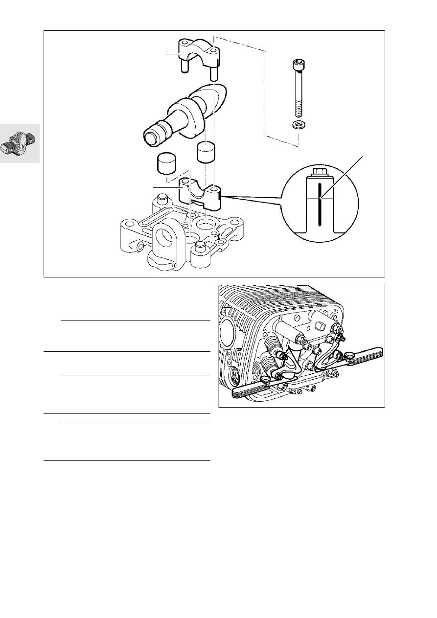
Remove camshaft bearing cap (1).

•

Remove camshaft and bearings (2).

•

Remove bucket-type tappets.

e

 Caution:

Do not accidentally confuse the bucket-type tap-
pets.

•

Reassemble in the reverse order of work.

e

 Caution:

Note direction of installation (3) for camshaft bearing 
cap. The cutout on the rocker shafts must be 
aligned with the retaining holes.

L

 Note:

Locate pushrods in ball cups on rockers and hold 
the rockers together with a rubber band to secure 
the pushrods in position.

X

 Tightening torque:

M 8 screw in rocker shaft bearing cap ......... 15 Nm
M 8 screw for camshaft bearing cap  ........... 15 Nm

•

Reposition the bearings until minimum endplay is 
obtained.

End float of rocker:
min....................................... 0.05 mm (0.00197 in)
max. ...................................... 0.40 mm (0.01575 in)

1

2

3

M8

 x

 6

5

RS110090

RS110100

11.61

Removing cylinder head

M6 x 30

M6 x 30

M6 x 30

M10 x 70

RS110110

11.62

Dismantling, checking, repairing and 
re-assembling cylinder head

Removing and installing valves

e

 Caution:

Do not scratch sealing face on cylinder head. Place 
the head on a clean, scratch-free surface.

•

Attach valve spring tensioner, 
BMW  No. 11 5 690, to cylinder head.

•

Clamp the valve springs.

•

Separate valve collet from spring plate by striking 
the valve head gently.

•

Remove valve collet sections.

•

Relieve tension on valve springs.

•

Remove top/bottom spring plates, valve springs 
and valves

Removing valve stem seals

•

Pull off valve stem seal with pliers, 
BMW No. 11 1 250.

L

 Note:

If a valve is removed, the valve stem seal must be 
renewed.

11 1 250

11 5 690

RS110130

11.63

Checking valves for wear

•

Clean combustion residue from valves.

•

Check valve dimensions.

a

See Technical Data.

Remachining valve seat

e

 Caution:

Width (B) and diameter (D) must always be 
maintained when remachining the valve seat.

a

See Technical Data.

Checking and repairing cylinder head

•

Remove combustion residues from combusion 
chamber.

•

Check sealing face for damage/distortion, and 
skim flat if necessary.

Skimming sealing face: 

...............max. 0.2 mm (0.00787 in) metal re-moval

Checking valve guide for wear

•

Check valve guide bore.

a

See Technical Data.

B

D

RS110890

11.64

Replacing valve guides

•

Heat cylinder head slowly and uniformly to 
200 °C in a suitable oven.

e

 Caution:

Wear protective gloves when handling heated parts.

•

Drive out valve guides with 6/5 mm 
(0.236/0.197 in) dia. extractor pin, 
BMW No. 11 5 672/674, from the combustion 
chamber side.

•

Allow cylinder head to cool down to room tem-
perature (app. 20 °C).

•

Examine valve guide bore for:

–

wear,

–

widening taper and

–

correct dimensions in H7 tolerance range 
(12.500...12.518 mm)(0.4921...0.4928 in).

L

 Note:

Valve guides are installed in the cylinder head with 
an interference fit of 0.015...0.044 mm 
(0.00059...0.00173 in).

If valve guide bore is undamaged and dimen-
sions are within correct 12.5 H7 tolerance range:

•

Use original 12.5 U6 (12.533...12.544 mm)
(0.4934...0.4939 in) valve guide.

•

Measure valve guides with micrometer.

If valve guide bore is undamaged but slightly 
larger than the 12.5 H7 tolerance range:

•

Use replacement valve guide 12.550...12.561 
mm (0.4941...0.4945 in).

If valve guide bore is damaged or not to correct 
dimensions in 12.5 H7 tolerance range:

•

Use an oversize 12.7U6 (12.733...12.744 mm)
(0.5013...0.5017 in) valve guide.

Repair method 1 – ream out the bore
(if bore is damaged or not to correct dimensions) 

•

Determine actual diameter of valve guide using 
micrometer.

•

Open out bore with Ø12.7 H7 mm 
(12.700...12.718 mm) (0.5...0.50071 in) reamer.

Repair method 2 – lathe-turn the valve guide (bore 
must not be damaged)

•

Determine actual diameter of bore with internal 
measuring tool.

•

Calculate the nominal diameter of the valve 
guide:

Nominal diameter of valve guide = bore dia. + inter-
ference-fit value (0.015...0.044 mm) 
(0.00059...0.00173 in).

•

Use an oversize 12.7 U6 (12.733...12.744 mm) 
(0.5013...0.5017 in) valve guide.

•

Turn down oversize valve guide to nominal di-
mension.

•

Slowly heat cylinder head to 200 °C  in a suitable 
oven.

•

Immerse valve guide in liquid grinding paste.

•

Freeze valve guide with dry ice..

e

 Caution:

Immediately before pressing in, the temperature 
must be –40 °C.

•

Place heated cylinder head flat on workbench or 
a similar surface.

•

Attach chilled valve guide to 6/5 mm 
(0.236/0.197 in) dia. pressing-in arbor 
BMW No. 11 5 671/673.

•

Insert valve guides into cylinder head with no de-
lay.

•

Allow cylinder head to cool down to room tem-
perature, app. 20 °C.

•

Inspect bore in valve guide.

L

 Note:

Valve guides for repair purposes have an internal di-
ameter of 6.01 H7 mm (5.01 H7 mm/R 850). 
In most cases, the bore after pressing in the valve 
guide is in the 6.00 H7 mm (5.00 H7 mm/R 850) tol-
erance range. 
If the bore is too narrow, it should be opened out.

11.65

Installing valve and valve stem seal

L

 Note:

If a valve was removed, the valve stem seal must be 
renewed.

•

Oil the stem when installing the valve.

•

Push the 6 mm (0.236 in) dia. assembly sleeve 
(arrow), BMW No. 11 1 960, on to the valve stem.

•

On 5 mm (0.197 in) dia. valve stems, shrink a 
short section of shrink-fit tube on the end of the 
valve stem.

•

Install the valve stem seal with a 6/5 mm 
(0.236/0.197 in) dia. drift,
BMW No. 11 5 601/602.

e

 Caution:

Remove the assembly sleeve and the shrink-fit tube.

•

Fit lower spring plate, valve spring and upper 
spring plate. 

•

Compress the valve springs with the clamping 
tool, BMW No. 11 5 690 

L

 Note:

Insert the taper valve collets using grease (to simpli-
fy assembly).

e

 Caution:

Ensure that valve collets are correctly seated in the 
valve stem grooves.

•

Relieve tension on valve springs.

•

Check valves for leakage (blow-by).

11 5 690

11 5 600

11 1 960

RS110160

11.66

Removing cylinder barrel

•

Unscrew and remove guide rail bearing 
screw (1).

•

Unscrew and remove cylinder retaining screws, 
and remove cylinde

e

 Caution:

When removing cylinder, ensure that the piston 
does not strike the engine block.

Removing/dismantling piston

•

Remove both retaining rings on piston pin.

•

Press out piston pin by hand.

•

Remove piston.

•

Carefully remove piston rings with piston ring pli-
ers.

•

Remove carbonized oil from base of piston/clean 
the piston.

e

 Caution:

Do not accidentally confuse pistons, piston pins or 
piston rings.

1

RS110170

11.67

Checking pistons and cylinders

Reference temperature 
for measurements:
 ..................................... 20 °C.

•

Measure cylinder bore with internal probe at 
20 mm (0.787 in) and 100 mm (3.937 in) from the 
top in direction of piston pin, and again at a right 
angle to the first measurement.

a

See Technical Data.

Measuring plane A :...................... 6 mm (0.236 in)

a

See Technical Data.

•

Install piston rings in cylinder.

•

Determine piston ring clearance using feeler 
gauge.

a

See Technical Data

Assemble pistons

•

Carefully fit piston rings to piston in the following 
sequence, using piston ring pliers: 
3rd grooveEqual-chamfer ring 
2nd groove Micro-taper compression ring 
M-ring (R 850) m Ø TOP 4 DZ
1st groove Micro-taper compression ring
B-ring (R 850) SPT TOP

•

Determine top runout of piston rings.

a

See Technical Data

e

 Caution:

The tubular-spring ring gap must be at 180° to the 
equal-chamfer ring gap. 
Install with the "Top" uppermost.

10

0

20

RS110180

A

RS110970

RS110200

1.

2.

3.

R 850

RS110190


Content   ..  12  13  14  15   ..