BMW AG Motorcycle (R 850 C, R 1200 C). Manual - part 22
 

  Index      Manuals     BMW AG Motorcycle (R 850 C, R 1200 C). Repair Manual


Search            


Content   ..  20  21  22  23   ..


BMW AG Motorcycle (R 850 C, R 1200 C). Manual - part 22


33.14

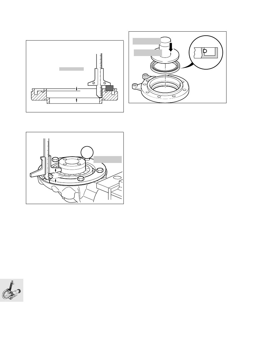
Shimming housing cover

•

To obtain the correct roller bearing preload, the 
housing cover must be shimmed. 

•

Using depth gauge, BMW No. 00 2 550, meas-
ure distance a.

•

Place measuring ring, BMW No. 33 2 601, in po-
sition and secure it.

•

Measure from the outer ball bearing race through 
the cutout in the measuring ring to the housing 
joint face and determine distance b.

•

Distance a – distance b = shim thickness (without 
preload).

•

Apply a light coat of grease to the selected shim 
washer, and install it.

Preload:............ 0.05...0.1 mm (0.0020...0.0039 in)

Installing housing cover

•

Lightly oil the lip and outer edge of the sealing 
ring.

•

Using drift, BMW No. 33 1 870, and handle, 
BMW No. 00 5 500, drive in the sealing ring.

•

Install O-ring and apply a light coat of oil/grease.

•

Heat housing cover to 80 °C (176 °F)/install. 

•

Tighten retaining bolts in a crosswise pattern.

X 

Tightening torque:

Housing cover.............................................. 35 Nm

Installing splined element

•

Coat splines on input pinion with Staburags 
NBU 30 PTM
.

•

Fit sliding element to drive pinion.

•

Locate retaining ring with gentle blows (plastic 
hammer).

a

00 2 550

KR330290

b

33 2 601

C330080

C330120

33 1 870

00 5 500

33.15

Removing/installing rear swinging 
fork

Removing rear swinging arm

•

Detach the lower suspension strut mount (1)

.

•

Force off the left swinging arm bearing cap using 
two screwdrivers in the holes.

•

Loosen the free swinging arm bearing journal.

•

Detach the fixed swinging arm bearing journal.

•

Using pull rod, BMW No. 00 8 581, and impact 
weight, BMW No. 00 8 582, pull out the fixed 
swinging arm bearing journal.

•

Remove the swinging arm bearing journal.

A

A

C330014

C330030

00 8 581

C330040

00 8 582

33.16

Removing and installing taper roller 
bearing

•

Pull the taper roller bearing out with counter-sup-
port, BMW No. 00 8 572, and internal puller
21/2, BMW No. 00 8 571.

•

Pull out outer race with internal puller 21/5, 
BMW No. 00 8 563.

•

To install the bearing, heat the swinging arm to 
80 °C (176 °F).

•

Bearing with drift, BMW No. 33 5 700 

Removing and installing flexible gaiter

•

Pull flexible gaiter with circlip out of swinging 
arm.

•

When installing, coat inner and outer sealing lips 
(arrows) with Staburags NBU 30 PTM.

e

 Caution:

Drive shaft clearance when suspension is com-
pressed: 
aperture in retaining ring must be horizontal.

Removing drive shaft

•

Press off drive shaft.

e

 Caution:

Avoid scratching painted parts; use an underlay if 
necessary.

Checking universal joint for wear

•

Determine end float and face runout.

Installing drive shaft

•

Coat the splines on the output shaft with 
Staburags NBU 30 PTM.

•

Fit drive shaft to output shaft.

•

Engage the snap ring with gentle blows (plastic 
hammer).

LT330370

00 8 563

00 8 571

00 8 572

KR330340

C330050

KR330360

33.17

Installing rear swinging arm

•

Slide swinging arm over drive shaft as far as pos-
sible until rubber gaiter connects on housing 
neck.

•

Install fixed bearing journal (1).

•

Screw in free bearing journal (2).

•

Tighten fixed bearing journal.

•

Tighten free bearing journal.

•

Tighten locknut (3).

•

Install the left swinging arm bearing cap.

e

 Caution:

Make sure that the O-ring is in good condition.
The drain hole must point down.

•

Secure suspension strut (1).

X 

Tightening torque:

Fixed bearing journal .................................... 10 Nm
Free bearing journal  ...................................... 7 Nm
Locknut ...................................................... 160 Nm
Suspension strut to swinging arm ................ 50 Nm

A

A

C330014

2

3

1

33.18

Installing rear wheel drive

•

Coat splines at sliding element (arrow) with 
Staburags NBU 30 PTM.

•

Offer up the rear wheel drive assembly and guide 
the sliding element into the drive shaft.

X 

Tightening torque:

Rear wheel drive to swinging arm................  21 Nm

•

If necessary, fill with oil.

Fill quantity:
(up to lower edge of thread on oil filler plug)
Initial 
filling ...........app. 0.20 l (0.35 Imp. pint/0.21 US quart)
During oil 
changes .....app. 0.18 l (0.32 Imp. pint/0.19 US quart)

Oil grade:
Brand-name hypoid gear oil, SAE 90, API class GL 5

•

[ABS] Install the brake disc in the previously 
marked position.

•

Install the rear wheel.

•

Install brake caliper

e

 Caution:

Do not damage brake pads; do not tilt when install-
ing.

•

Install speedometer signal transmitter.

•

[ABS] Install sensor.

•

[ABS] Check that sensor gap is correct.

ABS rear
sensor gap: 
........ 0.50...0.55 mm (0.019...0.021 in)

C330011

33.19

Removing and installing 
suspension strut

L

 Note:

To remove the suspension strut, support the rear 
axle.

X 

Tightening torque:

Suspension 
strut to swinging arm/rear frame................... 50 Nm

33.20

34.1

Contents

Page

34

Technical data 

................................................................................................................................3

Removing and installing front brake caliper 

.................................................................5

Dismantling and assembling front brake caliper 

........................................................6

Dismantling front brake caliper

 .................................................................................................6

Assembling front brake caliper

 .................................................................................................6

Removing and installing rear brake caliper 

...................................................................7

Dismantling and assembling rear brake caliper 

.........................................................8

Dismantling rear brake caliper

 ..................................................................................................8

Assembling rear brake caliper

 ..................................................................................................8

Removing and installing front brake disc 

.......................................................................9

Removing/installing rear brake disc 

................................................................................10

Removing and installing front ABS sensor 

..................................................................11

Adjusting front ABS sensor gap 

.........................................................................................12

Marking sensor wheel

 .................................................................................................................12

Checking and adjusting sensor gap

 .....................................................................................12

Removing and installing rear ABS sensor 

....................................................................13

Adjusting rear ABS sensor gap 

..........................................................................................14

Marking sensor wheel

 .................................................................................................................14

Checking and adjusting sensor gap

 .....................................................................................14

Removing and installing rear brake master cylinder 

..............................................15

Checking and adjusting reliefclearance of piston rod

 ..................................................15

Removing and installing brake pedal 

..............................................................................15

Removing and installing ABS unit 

.....................................................................................16

34 Brakes


Content   ..  20  21  22  23   ..