BMW AG Motorcycle (R 850 C, R 1200 C). Manual - part 21
 

  Index      Manuals     BMW AG Motorcycle (R 850 C, R 1200 C). Repair Manual


Search            


Content   ..  19  20  21  22   ..


BMW AG Motorcycle (R 850 C, R 1200 C). Manual - part 21


33.6

•

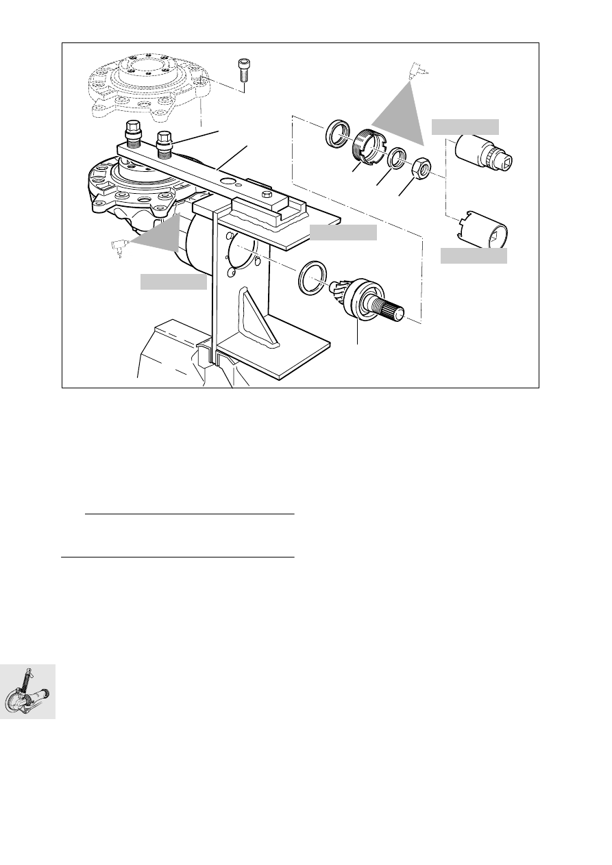
Bolt the rear wheel drive to the retaining fixture, 
BMW No. 33 1 510/511.

•

Bolt the locking arm (1) to the retaining fixture.

•

Screw threaded bushings (2) down on to the rear 
wheel drive and secure them with the wheel 
studs.

•

Heat hex nut (3) at the input bevel pinion to 
100 °C (212 °F) and unscrew with 36 mm (1.42 in) 
socket wrench insert and reducing ring,
BMW No. 33 1 720.

L

 Note:

If necessary, use cross-handle with two tubular ex-
tensions.

•

Pull off thrust ring (4).

•

Heat the housing to max. 120 °C (248 °F) and un-
screw threaded ring (5) with pin wrench, 
BMW No. 33 1 700.

•

To remove the input bevel pinion (6), remove the 
crown wheel.

a

............................See “Removing crown wheel”

•

Heat the bearing seat to max. 120 °C (248 °F).

•

Using an aluminium drift, carefully force the input 
bevel pinion outwards and remove it.

h

100

h

120

C330011

33 1 700

33 1 720

33 1 510

33 1 516

2

1

5

4

3

6

h

120

33.7

Disassembling input bevel pinion

•

Remove outer bearing race (1).

•

Pull spacer ring (2) out of housing.

•

Clamp input bevel pinion (3) into vice with pro-
tective jaws (splines facing upwards).

•

Using puller, BMW No. 00 7 500, pull off both 
bearings at the same time.

•

Take off ball thrust bearing (4), inner race (5), roll-
er bearing cage (6) and outer race (7).

Removing needle roller bearing for input bevel 
pinion

•

Heat the housing to 130 °C (266 °F).

•

Pull out the outer race of the needle roller bearing 
with puller, BMW No. 00 8 573, and threaded 
spindle extension, BMW No. 00 8 575.

Installing needle roller bearing for input bevel 
pinion

•

Heat the needle roller bearing seat to 100 °C 
(212 °F).

•

Press in needle roller bearing using drift or the in-
put bevel pinion.

C330021

3

5

7

6

4

1

2

KR330100

00 7 500

00 8 575

C330100

00 8 573

33.8

Assembling input bevel pinion

•

Heat the inner race (1) to 100 °C (212 °F) and 
push onto input bevel pinion (2) as far as the 
stop.

•

Push the outer race (3) together with the roller 
cage (4) on to the inner race.

•

Heat ball thrust bearing (5) to 100 °C (212 °F) and 
push fully on to input bevel pinion.

•

Allow input bevel pinion to cool down.

C??????

KR330131

3

5

4

1

2

h

100

h

100

33.9

Installing input bevel pinion

•

Lightly oil the sealing ring at the sealing lip and 
round the outer edge.

•

Press/drive sealing ring (1) with drift,  
BMW No. 33 1 770
, and handle,  
BMW No. 00 5 550
, into threaded ring (2).

•

Heat the housing to 120 °C (248 °F).

•

Insert the input bevel pinion (3) complete with 
spacing washer (4).

•

Insert outer race (5).

•

Coat threaded ring (6) with Hylomar SQ 32 M.

•

Tighten threaded ring with pin wrench,
BMW No. 33 1 700.

•

Place thrust ring (7) in position.

L


Note:

Ensure that the lip of the shaft seal is perfectly 
aligned on the thrust ring.

•

Tighten hex nut (8) with 36 mm (1.42 in) socket 
wrench insert and reducing adapter,
BMW No. 33 1 720.

e

 Caution:

Nut must not damage shaft sealing ring.

X 

Tightening torque:

Threaded ring 
(thread cleaned + Hylomar SQ 32 M)  ........ 118 Nm
Nut for input bevel pinion
(thread cleaned + Loctite 270).................... 200 Nm

33 1 700

C330025

33 1 720

5

6

7

3

8

4

h

120

C330110

33 1 770

33.10

Removing and dismantling the crown 
wheel

•

Remove housing cover (1) with crown wheel (2) 
and bearing (3).

•

Heat housing cover to 100 °C (212 °F) and pull it 
off.

•

Force shaft seal (4) out of housing cover with 
drift.

•

Clamp crown wheel in vice with protective jaws.

•

Insert thrust block (arrow), BMW No. 33 1 307.

•

Use puller, BMW No. 33 1 830, to pull off the 
deep-groove ball bearing.

3

2

4

h

100

C330022

1

33 1 830

KR33018

33 1 307

33.11

•

Using puller, BMW No. 00 7 500, pull taper roller 
bearing off crown wheel.

•

Pull out the outer race using internal puller, 
BMW No. 00 8 560.

Assembling/installing crown wheel

•

Heat the housing to 80 °C (176 °F).

•

Insert the outer race in the bearing seat with drift, 
BMW  No. 23 4 670, and handle,  
BMW  No. 00 5 500
.

•

Check that outer race is correctly seated by 
striking gently.

L

 Note:

If new parts are installed (e.g. taper roller bearing), 
check tooth backlash and adjust if necessary.

•

Place the existing spacer ring (1) on the crown 
wheel.

•

Heat taper roller bearing (2) to 80 °C (176 °F) and 
push it on.

•

Install crown wheel (3).

•

Heat deep-groove ball bearing (4) to 80 °C 
(176 °F) and place it in position.

KR333019

00 7 500

00 8 560

KR330200

C330230

23 4 670

00 5 500

h

80

C330240

4

3

1
2

h

80

h

80

33.12

Checking/adjusting backlash

•

Attach measuring device, BMW No. 33 2 620, 
with dial gauge to crown wheel and secure to 
housing with the knurled screw.

•

Attach measuring arm, BMW No. 33 2 604, cen-
trally to crown wheel.

•

With the palm of the hand, press the crown wheel 
into the housing and turn to and fro to check 
tooth backlash.

L

 Note:

Check tooth backlash at three points 120 degrees 
apart; turn the bevel pinion with the crown wheel.

•

Compensate for excessive backlash by inserting 
a thinner shim washer, and for insufficient back-
lash by inserting a thicker shim washer (1).

Backlash:
(adjust 
without oil)....... 0.07...0.16 mm (0.0027...0.0063 in)

33 2 604

C330060

33 2 620

90

°

C330070

1

C330240

33.13

Checking tooth contact pattern

•

The tooth contact pattern must be checked if the 
gear set, housing or input bevel pinion bearing 
have been renewed.

L

 Note:

The contact pattern is adjusted at the shim washer (1) 
on the input bevel pinion.

•

Degrease the tooth flanks on crown wheel and 
pinion, and coat with engineer’s blue.

•

Insert the crown wheel, press into housing with 
the palm of the hands and turn to and fro.

•

If the correct spacer disc is installed, the follow-
ing contact pattern appears with no load applied.

L

 Note:

The contact point is central on front flank V.
The contact point is closer to the larger diameter on 
back flank R.

e

 Caution:

Teeth should never make contact at the smaller di-
ameter.

•

If this contact pattern is obtained, a thinner shim 
washer must be installed.

•

If this contact pattern is obtained, a thicker shim 
washer must be installed.

KR33025

1

KR330260

KR330270

KR330280


Content   ..  19  20  21  22   ..