BMW AG Motorcycle (K1100LT, K1100RS). Manual - part 44
 

  Index      Manuals     BMW AG Motorcycle (K1100LT, K1100RS). Repair Manual


Search            


Content   ..  42  43  44  45   ..


BMW AG Motorcycle (K1100LT, K1100RS). Manual - part 44


62.7

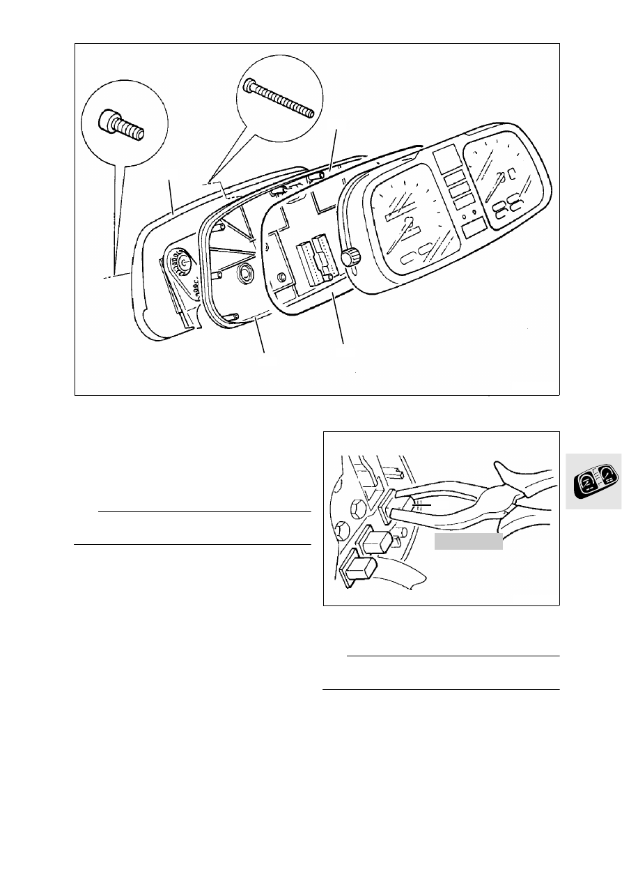
Disassembling and assembling 
instrument cluster

•

Release instrument support bracket (1).

•

Release housing cover (2) and remove together 
with gasket (3).

•

Instrument housing (4).

•

Assemble in the reverse order of disassembly.

L

 Note:

Ensure gasket is fitted in correct position.

Removing and installing indicator lamp

•

Grip indicator lamp (1) diagonally with relay pli-
ers, BMW No. 61 1 250, and pull out or press in.

L

 Note:

Do not damage conductor tracks.

LT620030

3

1

4

2

61 1 250

LT620040

1

62.8

Removing and installing p.c. board

•

Release securing screws and carefully lift out 
p.c. board (1).

L

 Note:

Do not damage p.c. board when removing and 
installing.
Ensure plug contacts are fitted correctly.

Removing and installing quartz clock

•

Carefully remove frame (1) by pulling upwards.

•

Carefully press retaining hooks towards the out-
side in the sequence (2,3) and (4,5).

•

Remove quartz clock (6) by pulling upward.

•

Install in the reverse order of removal.

Removing and installing frame for indicator 
lamps

•

Carefully press hooks (arrows) towards the out-
side.

•

Carefully lift out frame (7,8).

Removing and installing p.c. board for fuel 
gauge

•

Release screws (1).

•

Lift out p.c. board (2).

L

 Note:

Do not bend p.c. board while installing.

LT620050

1

LT620060

1

2

6

4

3

5

LT620070

7

8

LT620080

1

2

62.9

Removing and installing revolution counter

•

Release screws (1).

•

Lift out revolution counter (2).

Removing and installing speedometer

•

Release screws (3).

•

Completely pull out reset button (4) to the right.

•

Lift out speedometer (5).

LT620090

1

2

LT620100

5

4

3

62.10

Removing and installing p.c. board for gear indi-
cator

•

Remove tachometer.

•

Carefully pull pointer (1) off the spindle.

•

Release screws (2).

•

Remove dial face (3).

•

Release screws (4).

•

Lift out p.c. board (5).

L

 Note:

Note position of spacer (6).

LT620110

2

4

1

3

5

6

63.1

Contents

Page

63

Technical Data

............................................................................................................................... 3

Disassembling and assembling headlights 

....................................................................5

Adjusting headlights 

...................................................................................................................6

63 Lights

63.2

63.3

63

Technical Data

K 1100 LT

K 1100 RS

Lights

Headlight

Halogen rectangular headlight with two-stage 
manual range adjustment

Bulbs

High beam/low beam

H 4 halogen bulb 55/60 W, asymmetric

Parking light

12 V/4 W

Rear light

12 V/10 W

Brake light

12 V/21 W

Turn signal light

12 V/21 W

63.4


Content   ..  42  43  44  45   ..