BMW AG Motorcycle (K1100LT, K1100RS). Manual - part 43
61.11
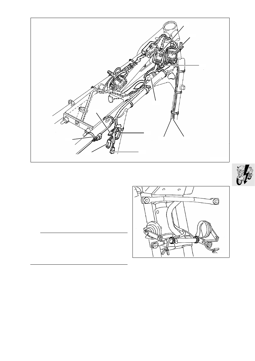
View from right
1. Right multi-function switch connection
2. Ignition lock connection
3. Handbrake light switch plug connection
4. Hall generator plug connection
5. Hall generator line
6. Oil pressure switch line
7. Brake light switch plug connection
8. Plug connection for fuel pump/fuel warning lamp
9. Transmission switch plug connection
10.Inductive pulse generator plug connection
11.Electric side stand switch connection
L
Note:
Arrange wiring loom without kinks and chafing
points; first install central electrics box.
Note arrangement and number of cable clips. Thinly
coat central earth (ground) point (metalically bright)
with contact grease.
X
Tightening torque:
Earth (ground) connection .............................. 9 Nm
Wiring arrangement fairing bracket,
[RS]
LT610080
11
6
3
4
7
2
1
5
8
10
9
LT610090