BMW AG Motorcycle (K1100LT, K1100RS). Manual - part 40
 

  Index      Manuals     BMW AG Motorcycle (K1100LT, K1100RS). Repair Manual


Search            


Content   ..  38  39  40  41   ..


BMW AG Motorcycle (K1100LT, K1100RS). Manual - part 40


46.21

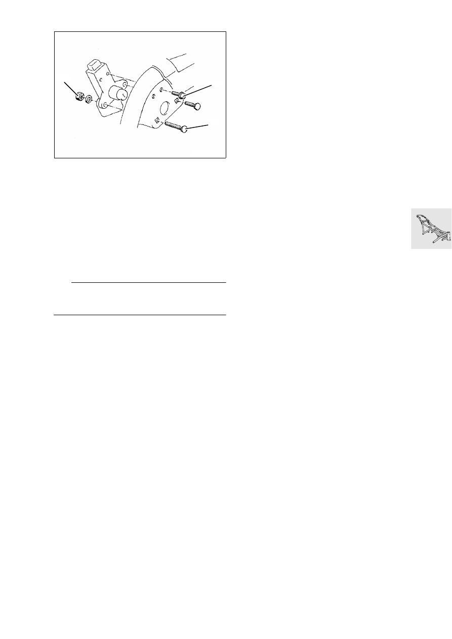
Removing and installing seat lock

1. Saucer-head screw
2. Phillips-head screw
3. Stop nut

Removing and installing handle

•

Lever out spring using screwdriver, remove 
spring seat.

•

Detach handle.

•

Remove spring with second spring seat.

•

Install in the reverse order of removal.

L

 Note:

Grease the pivot point a little before installing han-
dle. Spring seats must engage in the grooves.

LT510040

2

1

3

46.22

Installing frame

•

Installation basically takes place in the reverse 
order of removal.

•

Place frame on drive train and firmly tighten 
screws and bolts in the specified order.

1. Screw in all 5 screws loosely, i.e. not as far as 

they will go. Fit a 1 mm thick spacer ring, inner 
support ring at the front right between the cylin-
der head and frame strut.

2. Firmly tighten screws 1,4 and 3.
3. Measure distance at front left and fit outer sup-

port ring, firmly tighten screws.

4. Measure distance of mounting point on interme-

diate flange and firmly tighten screw.

X 

Tightening torque:

Frame to engine ........................................... 45 Nm

•

Install telescopic fork and adjust steering.

Setting torque:
Hexagon nut................................................  12 Nm

New bearing adjustement procedure:
Pre-tighten hexagon nut to........................... 25 Nm
Move steering from stop to stop several times, 
loosen hexagon nuts, retighten .................... 12 Nm

X 

Tightening torques:

Locking tube ................................................ 65 Nm
Hexagon nut ................................................ 65 Nm
Clamping screws of fork bridge.................... 15 Nm
Clamping block for handlebar ...................... 22 Nm

Setting dimensions:
Clutch play at handlebar 
lever ....................... 4 ± 0,5 mm (0.157 ± 0.0197 in)
Cable length at clutch release 
lever ............................ 75 ± 1 mm (2.953 ± 0.04 in)
Accelerator cable play............. 0,75 mm (0.0295 in)

•

Carefully fill and bleed brake system

X 

Tightening torques:

Brake line to handbrake cylinder .................. 11 Nm
Brake line to distributor ................................ 11 Nm
Brake line to brake caliper.............................. 7 Nm
Bleed screw ................................................... 7 Nm
[ABS II] Pressure modulator to holder ......... 17 Nm

LT460300

2

3

4

1

5

46.23

Removing and installing main centre 
stand

•

[RS] 

Remove lower section of fairing

.

•

Raise motorcycle with lifting gear, 
BMW No. 00 1 510, under the oil sump until 
stand is free to move.

•

Disconnect cable clips for side stand line.

•

Release retaining screws (1) and detach main 
stand together with side stand.

•

Install in the reverse order of removal.

L

 Note:

The retaining screws are micro-encapsulated and 
can therefore not be re-used. Clean thread and 
holes. Fit screws with Loctite 243.

Line arrangement for side stand

X 

Tightening torque:

Main stand to bearing block ......................... 41 Nm

LT460310

1

00 1 510

LT460320

LT460330

46.24

Disassembling and assembling side 
stand

D

isassembling side stand

•

Detach switch (1).

•

Detach tension springs (2).

•

Remove bracket (3) with spring.

•

Remove operating hook (4).

•

Remove leg spring (5).

•

Release securing screw (6) of side stand.

LT460340

1

2

6

4

5

3

46.25

Assembling side stand

L

 Note:

The securing screw of the side support is micro-en-
capsulated and cannot be reused. Clean thread and 
holes. Coat screws with Loctite 243 before insert-
ing.

•

Fit securing screw (6) with Loctite 243.

•

Fit leg spring (1) as illustrated.

•

Install operating hook (2) and bracket (3), note in-
stallation position (arrow).

e

 Caution:

Do not grease operating hook and bracket, 
increased dirt accumulation!

•

Attach tension springs (4).

•

Prior to installation, check condition of switch, 
contact spring must not be bent.

•

In no-load condition, there must be an air gap 
(clearance) between the contact spring (1) and 
contact point on the switch.

•

Secure switch with 2 O-rings (2) on the retaining 
screws for the bearing block.

•

Install stand with side stand.

X 

Tightening torque:

Side stand to bearing block ......................... 41 Nm

LT460350

2

4

3

1

LT460360

2

1

46.26

Disassembling and assembling main 
centre stand 

•

Detach tension springs (1).

•

Release screws (2) on left/right.

•

Release retaining ring (3).

•

Press out sleeve (4) on left/right.

•

Remove bearing block (5).

•

Loosen grease nipple (6).

•

Assemble in the reverse order of disassembly.

L

 Note:

Screws (2) are micro-encapsulated and must there-
fore not be re-used. Clean threades and holes and 
fit screws with Loctite 243.
Lubricate sleeves with SHELL RETINAX A.

LT460370

1

6

5

1

2

3

4

46.27

Checking switching function of side 
stand

•

Set vehicle on centre stand on even base or lift-
ing platform.

•

Spray switching kinematics of side stand with 
quick-action cleaner and fold out and in several 
times.

•

Completely fold out side stand and mark position 
on the base.

•

Make a second marking at the distance ”a” and 
a third marking at the distance ”b”.

Distances:
”a” .................................................. 95 mm (3.74 in)
”b” .................................................. 50 mm (1.97 in)

•

Fold in side stand and start engine.

•

Slowly fold out side stand, the engine must cut 
out in the area of dimension ”b”.

•

If the engine does not cut out, check or replace 
the switch.

e

 Caution:

Bending the contact spring can cause switch mal-
functions.
Therefore:
Never bend the contact spring!

•

Operate starter while slowly folding in side stand, 
the engine must start up in area ”b”.

•

If the engine does not start up, or if the side stand 
is difficult to move, check the switch or disas-
semble the side stand.

LT460380

a

b

46.28


Content   ..  38  39  40  41   ..