BMW AG Motorcycle (K1100LT, K1100RS). Manual - part 30
 

  Index      Manuals     BMW AG Motorcycle (K1100LT, K1100RS). Repair Manual


Search            


Content   ..  28  29  30  31   ..


BMW AG Motorcycle (K1100LT, K1100RS). Manual - part 30


33.7

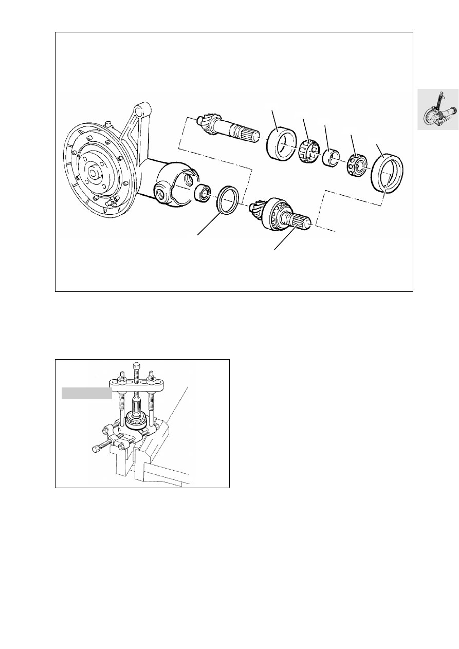
Disassembling drive bevel gear

•

Remove outer bearing race (2).

•

Remove spacer ring (3) from housing.

•

Clamp drive bevel gear (1) in vice with jaw guards 
(splines facing upward).

•

Using puller, BMW No. 00 7 500, remove both 
bearings at the same time.

•

Remove thrust bearing (4), inner race (5), bearing 
cage (6) and outer race (7).

LT33030

3

1

7

6

5

4

2

00 7 500

LT33040

33.8

Removing needle bearing for drive bevel gear

•

Destroy needle cage of needle bearing.

•

Heat housing to 130 °C.

•

Remove outer race of needle bearing with the aid 
of inner extractor, BMW No. 00 8 573, and sup-
port, BMW No. 00 8 570.

Installing needle bearing for drive bevel gear

•

Heat bearing seat of needle bearing to 100 °C. 

•

Press in needle bearing with suitable drift or the 
drive bevel gear.

LT330050

130°C 

00 8 570

RT330060

00 8 573

33.9

Assembling drive bevel gear

•

Heat inner race (4) to 100 °C and slide onto drive 
bevel gear (1) as far as it will go.

•

Slide outer bearing race (2) together with cylin-
der roller cage (3) onto inner race (4).

•

Heat ball bearing (5) to 100  °C and fit on drive 
bevel gear (1) as far as it will go.

•

Allow drive bevel gear to cool down.

LT330070

2

3

4

5

1

100°C 

33.10

Installing drive bevel gear

•

Drive sealing ring (2) into threaded rim (3) with 
the aid of drift, BMW No. 33 1 760, and retainer, 
BMW No. 00 5 550. 

•

Heat housing to 120 °C.

•

Fit drive bevel gear complete with spacer (1).

•

Fit outer race (6).

•

Coat threaded ring (3) with Hylomar SQ 32 M, 
thread turns must be free of grease.

•

Firmly tighten threaded ring with pin wrench, 
BMW No. 33 1 700.

•

Fit thrust ring (4).

L


Note:

Ensure the sealing lip of the shaft sealing ring is fit-
ted correctly at the thrust ring.

•

Coat hexagon nut (5) with Loctite 270, thread 
turns free of grease and firmly tighten using 
36 mm (1.4173 in) insert, BMW No. 33 1 720.

e

 Caution:

Nut must not damage shaft sealing ring!

X 

Tightening torquse:

Threaded ring 
(clean thread + Hylomar SQ 32M) .............. 118 Nm
Nut for drive bevel gear 
(clean thread + Loctide 273)....................... 200 Nm

LT330080

120°C 

1

6

2

3

4 5

00 5 500

LT330090

33 1 760

2

3

33.11

Removing and installing taper needle 
bearing in rear wheel drive

•

Remove needle bearing using inner extractor
21/4, BMW No. 00 8 573, and support 22/1, 
BMW No. 00 8 572.

•

Heat housing neck to 120 °C.

•

Press in needle bearing with inner race on drift, 
BMW No. 36 3 700.

RT33090

00 8 572

00 8 573

33.12

Removing crown wheel

•

Remove housing cover (1) with crown wheel (2) 
and bearing (3). 

•

Heat housing cover (1) to 100 °C and remove.

•

Drive shaft sealing ring (4) out of housing cover 
using drift.

•

Clamp ring gear in vice with jaw guards.

•

Fit pressure piece (arrow), BMW No. 33 1 307.

•

Using puller, BMW No. 33 1 830, remove deep-
groove ball bearing.

LT330110

1

3

2

4

100°C 

RT330120

33 1 830

LT330130

33 1 307

33.13

•

Remove taper roller bearing from ring gear with 
puller, BMW No. 00 7 500.

•

Remove outer bearing race with internal extrac-
tor, BMW No. 00 8 560.

Installing crown wheel

•

Heat housing to 80 °C.

•

Press outer race into bearing seat with drift, 
BMW No. 23 4 670, and handle, 
BMW No. 00 5 500.

L

 Note:

Check that outer race is correctly seated by light 
blows.

L

 Note:

The tooth backlash must be checked and adjusted 
if necessary if new parts have been installed, e.g. 
the taper roller bearing.

•

Fit existing spacer ring (1) on the crown wheel.

•

Heat taper roller bearing (2) to 80 °C and fit in po-
sition.

•

Install (3).

•

Heat deep groove ball bearing (4) to 80 °C and fit 
in position.

00 7 500

RS330140

00 8 560

LT330150

23 4 670

LT330160

00 5 500

RT330170

80°C

4

3

1

2

33.14

Checking/adjusting tooth backlash

•

Lock drive bevel gear in position with 36 mm 
(1.4173 in) insert, BMW No. 33 1 720. 

•

Fit measuring ring, BMW No. 33 2 600, with dial 
gauge on crown wheel and secure to housing 
with knurled screw (1).

•

Secure measuring arm, 
BMW No. 33 2 604,centrally on crown wheel.

•

With the palm of the hand, press crown wheel 
into housing and check gear backlash by turning 
backward and forward.

L

 Note:

Check the backlash at three points offset by 120 °, 
turn bevel gear with crown wheel.

•

Take up excessively large gear backlash by fit-
ting a thin spacer and too little gear backlash by 
fitting a thick spacer (1). 

Gear backlash:
(adjust without oil) ........................... 0.07...0.16 mm

........................................ (0.002756...0.006299 in)

33 2 604

RT330190

1

33 2 600

RT330200

90°

RT330210

1


Content   ..  28  29  30  31   ..