BMW AG Motorcycle (K1100LT, K1100RS). Manual - part 22
 

  Index      Manuals     BMW AG Motorcycle (K1100LT, K1100RS). Repair Manual


Search            


Content   ..  20  21  22  23   ..


BMW AG Motorcycle (K1100LT, K1100RS). Manual - part 22


23.5

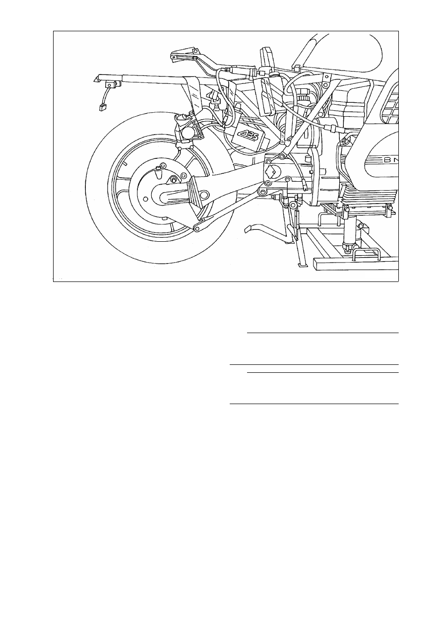
Removing transmission (gearbox)

Preparatory work

•

[RS] 

Remove left fairing side section 

.

•

Remove exhaust system.

•

Disconnect CAT plug connection for oxygen 
sensor.

•

Remove left and right footrest plate.

•

Remove rear mudguard.

•

Remove rear brake caliper.

•

Remove rear wheel.

•

Remove suspension strut.

•

Remove rear wheel drive.

•

Remove swinging arm.

•

Remove rear cover panel with coolant level 
equalising tank.

•

Remove Motronic control unit.

•

Remove battery.

•

[ABS I] 

Remove control unit.

•

[ABS I] 

Detach pressure modulators from holder 

and secure to rear section of frame.

•

[ABS I] 

Remove holder for pressure modulators.

•

[ABS II] 

Remove ABS unit.

•

Remove battery carrier.

•

Remove starter motor.

L

 Note:

Secure brake caliper, pressure modulators, reser-
voir and, footrest plate with adhesive tape to frame.

L

 Note:

For removal of ABS unit see Group 34, “Removing 
ABS unit”.

LT230430

23.6

Removing starter

•

Release positive and negative lead at starter.

•

Release mounting.

•

Pull out starter. 

LT230410

23.7

Removing bearing mount with main 
stand

•

Secure lifting gear, BMW No. 00 1 510, to the oil 
sump and slightly raise engine.

•

Release mounting for main stand.

e

 Caution:

The retaining bolts are micro-encapsulated and can 
therefore not be reused.

•

Cut through cable clip on main stand.

LT230440

00 1 510

LT230500

23.8

Removing transmission (gearbox)

•

Release retaining bolts.

•

Screw guide pins, BMW No. 23 1 820, in holes 
with fitted sleeve, long pin on right-hand side.

•

Slowly pull off gearbox.

e

 Caution:

Hold gearbox at installation height until the control 
rod can be seen completely, otherwise it can easily 
bend.

23 1 820

LT230450

23.9

Disassembling transmission (gear-
box)

Removing transmission cover.

•

Secure gearbox with holder (arrow “A”), 
BMW No. 23 1 600, to assembly stand.

•

Engage neutral.

•

Release idle lock (1).

•

Remove coil (2) and ball (4).

•

Release screws (3).

•

Heat bearing seat in transmission cover to 
100 °C 

•

Evenly press off transmission cover at three 
points (arrows).

LT230010

1

3

2

4

A

100°C

23.10

Disassembling/assembling transmis-
sion cover

Removing and installing bearing shell

•

Heat bearing cover to 100 °C. 

•

Remove bearing shell with Kukko support, 
BMW No. 00 8 560, and internal extractor 21/5, 
BMW No. 00 8 563. 

•

Fit bearing shell in transmission cover while still 
hot.

•

Drive bearing shell onto the bottom of its seat 
with drift, BMW No. 23 1 700, and handle 
BMW No. 00 5 500.

Removing and installing shaft sealing ring on 
input shaft

•

Drive out shaft sealing ring with drift from the in-
side.

•

Fit new sealing ring with drift, BMW No. 23 1 770 
and handle, BMW No. 00 5 500.

L

 Note:

If the coefficient of friction of the input shaft is to be 
checked, do not fit sealing ring until measurement 
has been completed.

Removing and installing locking lever

•

Release retaining ring (1) 

•

Lift short arm of spring over contact surface (ar-
row).

•

Remove lever and spring.

•

Install in the reverse order of removal.

LT230020

100°C

00 8 563

00 8 560

00 5 500

LT230030

23 1 770

23 1 770

LT230040

00 5 500

LT230050

1

23.11

Removing gear selector drum

•

Remove shafts (1) of gearshift forks.

•

Press pawl (2) towards the outside and secure 
with clamping fixture (arrow), 
BMW No. 11 5 500.

•

Tilt back input shaft by approx. 45° 

•

Turn gearshift forks towards the outside until 
guide pins are free.

•

Remove gear selector drum?(3).

L

 Note:

Note sleeves on guide pins.

Removing gearshift forks

1. Gearshift fork, 1st and 2nd gear
2. Gearshift fork, 5th gear
3. Gearshift fork, 3rd and 4th gear

11 5 500

LT230060

1

3

2

11 5 500

LT230070

1

3

2

23.12

Removing transmission shafts

•

Heat bearing seat of input shaft (1) and the inter-
mediate shaft (2) to 100 °C.

•

Pull out both shafts together.

•

Remove input shaft (3).

Removing pawl

•

Using drift, drive out vent (arrow) from the inside.

•

Remove retaining ring (1) on guide rod.

•

Pull out guide rod.

•

Remove pawl retaining bracket together with 
pawl.

•

Remove retaining ring on pawl shaft.

•

Remove pawl from pawl retaining bracket.

LT230090

2

1

3

100°C

LT230100

1


Content   ..  20  21  22  23   ..