BMW AG Motorcycle (K1100LT, K1100RS). Manual - part 20
21.5
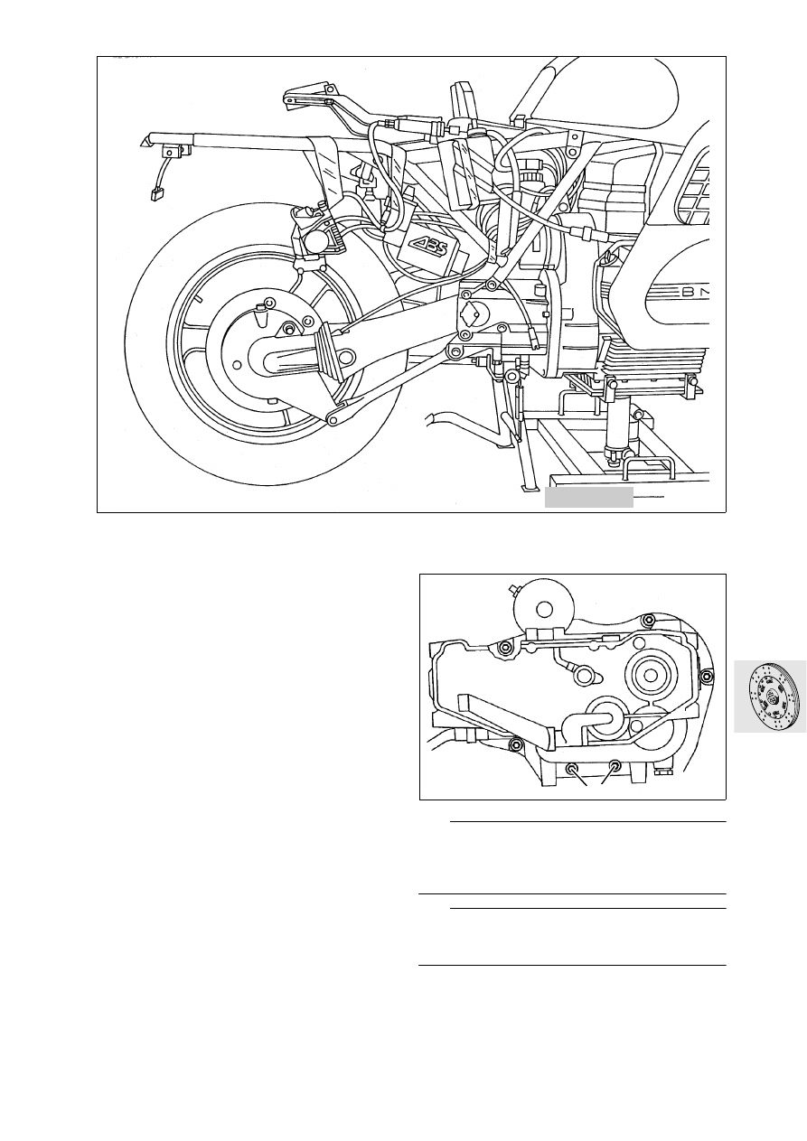
Removing clutch
•
Secure lifting gear, BMW No. 00 1 510, to the oil
sump.
•
Remove main stand.
•
Remove rear mudguard.
•
Remove right-hand footrest plate.
•
Remove Motronic control unit.
•
Remove battery.
•
[ABS I]
Remove ABS control unit.
•
[ABS I]
Secure pressure modulators to rear
section of frame.
•
[ABS II]
Remove ABS unit.
•
[ABS I]
Remove holder for demodulators.
•
Release bottom retaining bolts (1) holding trans-
mission.
•
Re-install main stand without switch for electric
side support.
•
Remove transmission together with the com-
plete rear wheel drive and rear wheel.
L
Note:
Keep transmission at installation height until the
clutch control rod can be seen completely, since it
can be easily bent.
L
Note:
To remove the ABS unit, see also Group 34, “Re-
moving ABS unit”.
LT210130
00 1 510
LT210140
1