BMW AG Motorcycle (K1100LT, K1100RS). Manual - part 8


  Index      Manuals     BMW AG Motorcycle (K1100LT, K1100RS). Repair Manual


Search            


Content   ..  6  7  8  9   ..


BMW AG Motorcycle (K1100LT, K1100RS). Manual - part 8


11.33

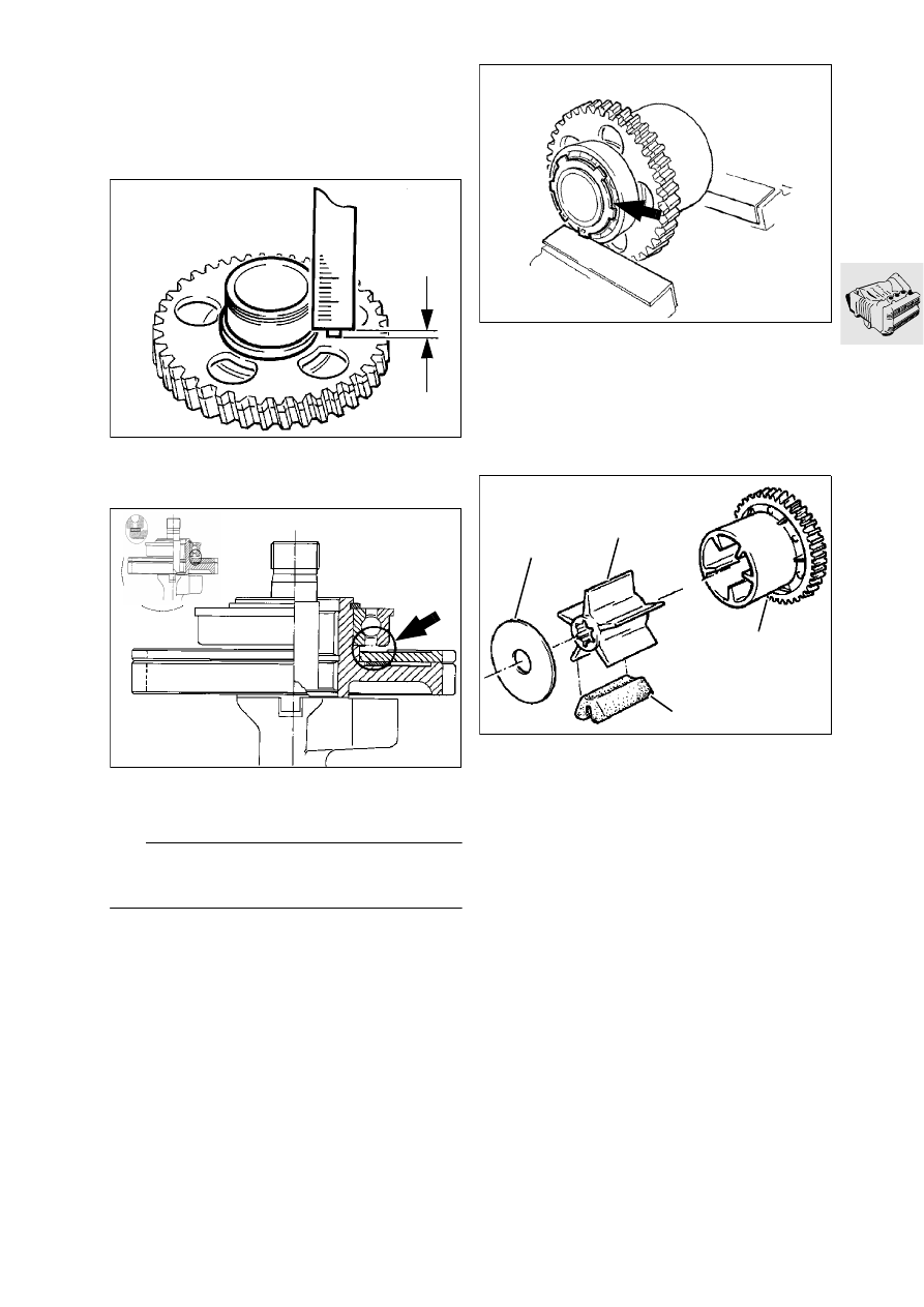
Assembling tensioning gear

Insert the tensioning spring.

Install tensioning gear with counter-holder, 
BMW No. 12 4 600.

Clamp the tensioning gear with damper housing 
together into a vice with soft jaws.

Measure distance “a” from ball bearing seat to 
tensioning gear.

Place a suitable spacing washer (arrow) on the 
tensioning gear.

L

 Note:

The thickness of the spacing washer must never ex-
ceed this measurement.

Heat the ball bearing to 80 °C and install it (with 
shoulder upwards).

Clamp the damper housing and the ball bearing 
together in the vice (with soft jaws).

Place the circlip (arrow) in the groove in front of 
the bearing, using Seeger circlip pliers.

The circlip must snap completely into the groove.

Installing damper

Insert damper rubbers (1) into damper
housing (2).

Push retaining plate (3) on to output shaft; heat 
the inner section of damper (4) slightly and press 
it on.

Push the damper housing on to the output shaft.

a

LT110470

LT110480

LT110490

3

4

2

1

LT110500

11.34

Assembling engine

Installing output shaft

Push circlip (1) and needle roller sleeve (2) on to 
the bearing point.

Place the output shaft in the crankcase.

L

 Note:

Gap of circlip (1) in crankcase (arrow).

1

2

LT110510

1

KR110521

11.35

Assembling the crankcase

Install O-rings (6,7) for the water and oil passag-
es.

Coat the sealing faces (which must be free from 
oil and grease) lightly with 3-Bond-1209.

Place the two halves of the housing together.

Screw in bearing bolts (4, 5) for the shouldered 
and needle roller bearings, and tighten alternate-
ly.

Tightening torques:

Shouldered bearing (4) ................................. 40 Nm
Needle roller bearing (5) ............................... 18 Nm
Retaining screws of two halves of the housing7 Nm

1

2

3

4

5

LT110530

6

7

KR110521

Installing oil mesh strainer

Note presence of O-ring (2).

Installing oil filter

Coat the oil filter sealing ring with oil.

Do not tighten the oil filter more than half a turn 
beyond the point where it makes contact.

Installing oil sump

Coat the sealing faces (which must be free from 
oil and grease) with 3-Bond 1209.

Tightening torques:

Retaining screws............................................ 7 Nm
Oil filter......................................................... 11 Nm

11.36

Measuring crankshaft bearing play

Measuring radial play

Crankshaft bearing points must be clean and 
lightly oiled.

Place the crankshaft in the crankcase and install 
the bearing caps so that the joint lines are 
aligned.

L

 Note:

Bearing caps 1…3 are marked; bearings 4 (thrust 
bearing) and 5 are not marked.

Tighten the bearings in the order shown, starting 
from the centre and working outwards.

Tightening torque:

Main bearings .............................................. 50 Nm

Turn the crankshaft to top dead centre at the 
bearing to be measured.

Take off the bearing cap.

Turn the crankshaft further by approximately an-
other 30°.

Wipe off oil at the bearing journal and bearing 
shell.

Measure bearing play with Plastigage Type Pg-1, 
BMW No. 00 2 590.

Place the Plastigage strip (arrow) over the entire 
width of the bearing, 6…8 mm (0.24…0.32 in) 
from the centre.

Tightening torque:

Main bearings .............................................. 50 Nm

L

 Note:

Do not turn the crankshaft any more.

Remove bearing cap.

Determine the width of the strip and thus the 
bearing play with the comparison scale (arrow).

Radial
clearance .... 0.020...0.056 mm (0.0008...0.0022 in)
Wear limit .............................. 0.110 mm (0.0043 in)

5

3

1

2

4

LT110540

LT110550

LT110560

11.37

Measuring endplay

Install the crankshaft and measure as for radial 
play.

Screw measuring fixture,
BMW No. 00 2 500, with dial gauge into the 
tapped hole for the timing case cover.

Move the crankshaft from one limit to the other 
and take the dial gauge reading.

Axial play..... 0.080…0.183 mm (0.0031…0.0072 in)
Wear limit .............................. 0.250 mm (0.0098 in)

Checking dimensions of crankshaft

If measured bearing play was too large, the di-
mensions of the crankshaft must be checked.
Regrinding stages “0” and “1” are available; the 
crankshaft is marked with the appropriate 
number of paint spots at the bearing point. If 
there are no paint spots, this indicates regrinding 
stage “0”.

Crankshaft dimensions.............. see Technical Data

LT110570

00 2 500

11.38

Installing crankshaft

Oil the bearings lightly before inserting the crank-
shaft.

Install the corresponding bearing caps with the 
grooves aligned.

L

 Note:

Bearing caps 1…3 are marked for identification; 
bearing caps 4 (thrust bearing) and 5 are not 
marked.

Tighten the bearings in the order shown, starting 
from the centre and working outwards.

Tightening torque:

Main bearings .............................................. 50 Nm

3

5

1

2

4

LT110580

11.39

Installing piston with conrod

Turn the corresponding crankpin to bottom dead 
centre.

The piston ring gaps must be offset by app. 120° 
in each case.

L

 Note:

The gap of the micro-chamfer ring in groove 2 is de-
termined by the pin.

Oil the piston rings, piston skirt and cylinder wall 
thoroughly.

LT110590

Using tensioning strap, BMW No. 11 2 925, com-
press the piston rings.

Insert the piston with conrod into the cylinder.

Drive the piston carefully into the cylinder with a 
hammer handle.

The arrow on the piston crown must point to-
wards the timing end of the engine (cyl. 1).

Make sure that the pistons are in the same 
weight category.

LT110600

11 2 925

11.40

Measuring big end bearing play

Turn the crankpin 30° away from bottom dead 
centre.

Wipe oil off crankpin and bearing cap.

Place Plastigage strip (arrow), Type PG-1,
BMW  No. 00 2 590, over the entire width of the 
bearing, 6…8 mm (0.24…0.32 in) away from the 
centre of the crankpin.

Attach the bearing caps with the joint lines 
aligned, and tighten them.

Tightening torque:

Big end bearings .......................................... 30 Nm

L

 Note:

The crankshaft must not be turned any more at this 
stage.

Tighten the big end bearings with wrench angle 
indicator (1), BMW No. 11 2 210.

Tightening torque:

Wrench angle   .................................................. 80°

Unscrew and remove the bearing cap.

Determine bearing play against comparison 
scale (arrow).

Bearing
play ............. 0.030…0.066 mm (0.0012…0.0026 in)
Wear limit .............................. 0.130 mm (0.0051 in)

If bearing shells are renewed, note paint marks 
on crankpin and on big end bearing.

Regrinding stages “0” and “1” are available; the 
crankpins are marked with a corresponding 
number of paint spots.

If there are no paint spots, this indicates regrind-
ing stage “0”.

L

 Note:

The crankshaft can only be reground in stage “0”, 
and must be hardened and finished afterwards.

Installing big end bearing

Move the crankpin of the cylinder concerned to 
bottom dead centre.

Oil the crankpin and attach the conrod.

Pull the protective tubes off the bolts.

Attach the bearing caps with the joint lines 
aligned, and tighten them.

Tightening torque:

Big end bearings .......................................... 30 Nm

Using wrench angle indicator,
BMW No. 11 2 500, tighten the big end bearing.

Tightening torque:

Wrench angle .................................................... 80°

LT110610

LT110620

11 2 210

1

LT110630


Content   ..  6  7  8  9   ..