BMW AG Motorcycle (K1100LT, K1100RS). Manual - part 7
 

  Index      Manuals     BMW AG Motorcycle (K1100LT, K1100RS). Repair Manual


Search            


Content   ..  5  6  7  8   ..


BMW AG Motorcycle (K1100LT, K1100RS). Manual - part 7


11.25

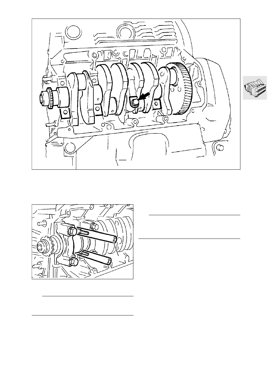
Removing crankshaft

Removing big end bearings

•

Move the piston in cylinders 1 and 4 to the bot-
tom dead centre (BDC) position.

•

Remove the big end bearing caps.

L

 Note:

Push protective tube (1) (app. 50 mm (2 in) long) on 
to big end bolts.

•

Repeat the work sequence at cylinders 2 and 3.

Removing main bearings

•

Take out all main bearing bolts except one (ar-
row).

•

Take off the bearing caps.

•

Take out the last bolt.

•

Take off the bearing cap, pressing the crankshaft 
in towards the housing while doing so.

L

 Note:

Bearing caps 1-3 are marked for identification. 
Bearing 4 (thrust bearing) and bearing 5 are not 
marked. Cylinder 1 = timing end of engine.

LT110330

1

LT110340

11.26

Removing pistons with conrods, strip-
ping down and re-assembling

Removing piston with conrod

•

Press the piston with conrod out from the crank-
shaft side.

Dismantling piston

•

Remove the circlip (1) at one side.

•

Press out piston pin (2) with drift, 
BMW No. 11 2 930.

•

Carefully remove piston rings (3).

•

Clean the piston.

1

3

1

2

LT110350

Checking piston dimensions

•

Measure piston diameter with a micrometer at 
distance “A”.

Make:  ...............................................Dimension “A”
KS............................................. 12.0 mm (0.472 in)
Mahle .......................................... 7.6 mm (0.299 in)

•

Measure piston ring side-flank clearance with 
feeler gauges.

•

Measure the piston ring end gap in the cylinder.

For side clearance and gap, see Technical data 
page 11.9

A

LT110360

11.27

Assembling pistons

•

Install piston rings, using piston-ring pliers.
1st groove: rectangular-section ring
2nd groove: micro-chamfer ring (note pin
for ring gap and TOP marking).
3rd groove: equal-chamfer ring with tubular
spring, (note TOP marking).

L

 Note:

The tubular spring gap must be offset by 180° from 
the equal-chamfer ring gap.

Checking cylinder dimensions

•

Set the internal micrometer to the nominal cylin-
der bore diameter.

•

Measure the cylinder bore at three heights and in 
a crosswise pattern: in the direction of forward 
travel and at a right angle to it.

Removing and installing small-end bushing

•

Press out the small-end bushing.

•

The gap in the new bushing, when pressed in, 
must be at an angle of 60° either to the left or the 
right of the centre axis.

•

Ream out the small-end bushing.

•

Drill the oil hole and deburr it.

e

 Caution:

It should be possible to push the piston pin through 
the small-end bushing with only light pressure.

•

Check that conrod bores are parallel.

•

The difference over the measured length “P” 
must not exceed 0.06 mm (0.0024 in).

Measured length “P”................... 150 mm (5.906 in)

1

2

3

LT110370

LT110380

30°

60°

60

°

LT110390

LT110400

11.28

Assembling pistons and conrods

L

 Note:

[LT] Modified conrod length and pistons from 1993 
model year on

•

Comply with conrod weight tolerances.

Weight tolerance .............................................± 4 g

•

Assemble piston and conrod.

L

 Note:

The oil bore in the conrod eye is on top in the in-
stalled position. The arrow marking on the piston 
crown must point in the forward-travel direction.

•

Install only pistons of the same make and the 
same weight category.

e

 Caution:

Renew the piston pin circlip each time it is removed.

Removing and installing crankshaft 
pinion and rotor flange

X 

Tightening torque:

Machine screw ............................................. 50 Nm

1

2

LT110410

11.29

Removing, dismantling and assem-
bling combined oil-water pump

Removing pump

•

Pull off the wires for the oil pressure and water 
temperature display at the switch.

•

Pull the wires out of the housing.

•

Remove housing cover (2) and loosen the gasket 
with light blows of a plastic-faced hammer.

•

Remove the housing and loosen the gasket with 
light blows of a plastic-faced hammer.

•

Pull off the housing.

Dismantling pump

•

Clamp the pump housing into a vise at the seal-
ing faces, using soft jaws.

•

Remove the impeller (5), holding the pump shaft 
to prevent it from moving.

•

Take off the impeller with spacing bushing (6).

•

Pull out pinion (8) and pump shaft (9).

•

Examine the pump housing for damage.

3

4

5

6

8

9

1

2

LT110422

11.30

Removing slipring seal and shaft sealing ring

•

Press out slipring seal (6) with a drift.

•

Using a 5 mm (0.2 in) wide screwdriver, carefully 
press out sealing ring (5).

Removing pressure relief valve

•

Loosen threaded union (12) and pull out
spring (13).

•

Pull valve piston (14) out with a magnet and ex-
amine it for damage.

Installing pressure relief valve

•

Oil valve piston (14) lightly before installing.

•

Insert spring (13) and insert and tighten the 
screw plug with a new seal.

X 

Tightening torque:

Screw plug (12) ............................................ 27 Nm

7

9

11

10

12

13

14

6

5

15

16

LT110432

Install the shaft sealing ring and slipring seal

•

Drive in sealing ring (5) from the water side with 
the open side downwards, using drift, 
BMW No. 11 1 640, and handle, 
BMW No. 00 5 500.

•

Press in slipring seal (6) with drift,
BMW No. 23 1 780, and handle, 
BMW No. 00 5 500.

Installing pump shaft and impeller

•

Oil pump shaft (7) lightly and push it into the 
housing from the oil side.

•

Place impeller (9) with spacing bushing (10) in 
position. When tightening, hold the pump shaft 
to prevent it from turning.

X 

Tightening torques:

Impeller screw (11) ....................................... 33 Nm
Oil pressure switch (15)................................ 40 Nm
Water temperature sensor or
Screw plug (16) .............................................. 9 Nm

11.31

Removing output shaft

Removing oil sump

•

After removing the screws, loosen the seal with 
light blows of a plastic-faced hammer.

Removing oil filter

•

Unscrew oil filter (1) with the oil filter wrench, 
BMW No. 11 4 650.

Removing lower section of crankcase

•

Take out retaining screws and screws (3) holding 
the output shaft.

•

With light blows of a plastic-faced hammer, loos-
en the gasket and take off the lower section of 
the housing. Note presence of O-rings.

•

Carefully lift out the output shaft; the needle roller 
bearing and circlip are loose on the shaft.

LT110440

2

3

1

Removing and installing oil level sight glass

•

Pierce the plastic disc with a large screwdriver 
and lever out the oil level sight glass.

•

Oil the sealing face of the oil level sight glass 
lightly and drive it in with a drift, 
BMW No. 00 5 550.

11.32

Stripping and assembling output shaft

Stripping down output shaft

•

Take off needle roller race (1) and circlip (2).

•

Pull output shaft (3) out of damper housing (4).

•

Drive the output shaft out of the inner section of 
the damper (5) with a plastic-faced hammer.

Stripping down tensioning gear

•

Clamp the damper housing into a vise with soft 
jaws, to take the load off circlip (7).

7

8

9

10

11

6

5

1

2

3

4

LT110450

7

LT110460

•

Remove circlip (7) with Seeger circlip pliers.

•

Using two-arm puller, BMW No. 00 8 400, and 
thrust block, BMW No. 33 1 307, pull off ball 
bearing (8).

•

Take off spacing ring (9).

•

Remove tensioning gear (10) with counter-hold-
er, BMW No. 12 4 600.

•

Remove tensioning spring (11).

L

 Note:

Inspect all parts for damage or wear.


Content   ..  5  6  7  8   ..