BMW AG Motorcycle (F 650 GS). Manual - part 30
 

  Index      Manuals     BMW AG Motorcycle (F 650 GS). Repair Manual


Search            


Content   ..  28  29  30  31   ..


BMW AG Motorcycle (F 650 GS). Manual - part 30


34.8

34 21 222 

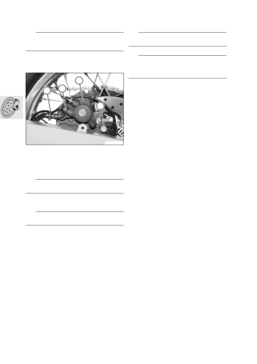
Removing and installing 

rear brake calliper

e

 Caution:

Refer to notes on the hazards involved in handling 
brake fluid.

•

Remove wheel cover together with chain cover.

•

Press the brake calliper against the brake disc in 
order to force the pistons back

•

Cut through cable tie (1).

•

[ABS] Remove fastener securing ABS sensor (4) 
and remove ABS sensor.

•

Disconnect brake line (2) at brake calliper and 
seal the line.

e

 Caution:

Do not operate the brake with the wheel removed.

–

Remove rear wheel.

a

....................................................See Group 36

e

 Caution:

Do not damage brake pads.

•

Remove brake calliper (3) from the rear swinging 
fork.

•

Installation is the reverse of the removal proce-
dure.

L

 Note:

Remove sealing rings for brake line.

e

 Caution:

Top up brake fluid and bleed brake system.
Operate brake several times until brake pads are 
correctly seated.

X 

Tightening torque:

Brake line to brake calliper ........................... 18 Nm
ABS sensor to bracket ................................... 9 Nm
Quick-release axle ..................................... 100 Nm
Wheel cover bracket to swinging arm............. 9 Nm

34 21 200 

Removing and installing rear 

brake pads

See Group 00

E340080

1

2

3

4

34.9

Removing and installing rear brake 
piston

–

Remove rear brake calliper.

•

Remove the split-pin keeper (1) from retaining 
pin (2).

•

Drive the retaining pin out towards the wheel 
side.

•

Remove brake pads (6).

•

Hold a cloth over the brake calliper.

e

 Caution:

Do not insert your fingers between the pistons; risk 
of injury.

•

Carefully press out brake piston (3), using a 
compressed air gun at the brake line connection.

•

Remove the two sealing rings (4, 5) from the 
brake piston bore.

•

Examine the brake calliper piston for damage.

•

Installation is the reverse of the removal proce-
dure: pay particular attention to the following.

•

Coat new sealing rings (4, 5) with brake fluid and 
install.

•

Coat the brake piston (3) with the assembly fluid 
supplied and install.

e

 Caution:

Keep the brake piston parallel with its bore when in-
stalling.

•

Using piston compressor, BMW No. 34 1 500, if 
necessary press the piston fully back.

•

Install the brake pads.

E340090

1

5

4

3

2

6

34.10

34 21 301 

Removing and installing 

rear brake disc

e

 Caution:

Do not operate the brake with the wheel removed.

–

Remove rear wheel.

a

....................................................See Group 36

L

 Note:

Retaining screws (1) are secured with Loctite 243 
and should be heated if necessary before removal.

•

Remove retaining screws (1) with brake disc.

•

Remove brake disc.

•

Installation is the reverse of the removal proce-
dure: pay particular attention to the following.

e

 Caution:

The inscription on the brake disc must face towards 
the outside.

•

Clean the threads of the securing screws and 
wheel hub, coat threads with Loctite 243 and in-
stall the screws.

X 

Tightening torque:

Brake disc to rear-wheel hub
(clean thread + Loctite 243)............................ 9 Nm

Checking brake disc for wear

See Group 00

Checking rear brake disc for lateral 
runout

•

Place motorcycle on its centre stand.

•

Remove wheel cover together with chain cover.

•

Attach dial gauge holder, BMW No. 00 2 500, to 
the rear swinging arm.

•

Using dial gauge, BMW No. 00 2 510, measure 
lateral runout.

Lateral runout.................... max. 0.25 mm (0.010 in)

Replacing primary sealing boot front 
brake master cylinder

See Group 00

E340100

1

E340110

00 2 500

00 2 510

34.11

Removing and installing front brake 
master cylinder

–

Place the motorcycle on its main (centre) stand.

e

 Caution:

Refer to notes on the hazards involved in handling 
brake fluid.

•

Drain the brake system.

•

Remove brake microswitch.

•

Disconnect brake hose (1) from the brake master 
cylinder.

•

Remove screws securing brake master 
cylinder (2).

•

Installation is the reverse of the removal proce-
dure: pay particular attention to the following.

L

 Note:

Replace the sealing rings for the brake hose.

e

 Caution:

Top up brake fluid and bleed brake system.
Operate brake several times until brake pads are 
correctly seated.

X 

Tightening torque:

Brake hose to brake master cylinder ............ 18 Nm
Brake master cylinder to handlebar ................ 9 Nm

32 72 119 

Removing and installing 

handbrake lever

See Group 32

Replacing primary sealing boot, 
rear brake master cylinder

See Group 00

34 31 001 

Removing and installing 

rear brake master cylinder

–

Place the motorcycle on its main (centre) stand.

e

 Caution:

Refer to notes on the hazards involved in handling 
brake fluid.
Do not operate the brake when dismantled.

•

Drain the brake system.

•

Disengage piston thrust rod (3).

•

Disconnect brake line (5).

•

Disconnect hose from reservoir (4).

•

Remove fasteners (6) securing brake master cyl-
inder.

•

Installation is the reverse of the removal proce-
dure: pay particular attention to the following.

•

Secure brake line to brake master cylinder.

E340200

1

2

E340250

3

6

5

4

34.12

e


Caution:

Top up brake fluid and bleed brake system.
Operate brake several times until brake pads rest on 
disc.

Play at piston thrust 
rod .............................. 0.5...1.5 mm (0.02...0.06 in)

X 

Tightening torque:

Brake line at master cylinder ........................ 18 Nm
Brake master cylinder to frame....................... 9 Nm

35 21 000 

Removing and installing 

footbrake lever

•

Remove footrest plate (1).

•

Disengage piston thrust rod (4).

•

Remove hexagon fit bolt (2).

•

Remove brake pedal (3), leaving torsion 
spring (5) on the frame.

•

Installation is the reverse of the removal proce-
dure: pay particular attention to the following.

L

 Note:

Grease the bearing bushing with 
Staburags NBU 30 PTM.
Check play at piston thrust rod and adjust if neces-
sary.
See removal and installation of brake master cylin-
der.

e


Caution:

Check operation of brake-light switch (6).

Play at piston thrust 
rod .............................. 0.5...1.5 mm (0.02...0.06 in)

X 

Tightening torque:

Brake pedal to frame.................................... 21 Nm

Checking play at piston thrust rod, 
adjusting if necessary

Checking play at piston thrust rod

•

With no load applied to the brake pedal, i.e. lug 
of lever against stop on frame (arrow), play must 
be perceptible at piston thrust rod (7).

L

 Note:

Adjust the piston thrust rod if no play is perceptible.

–

Adjusting play at piston thrust rod

a

........................................................ See below.

E340040

2

1

6

4

3

5

E340270

7

34.13

Adjusting play at piston thrust rod

•

Insert feeler gauge (1) 0.2 mm (0.008 in) thick be-
tween the lug of the brake pedal and the stop on 
the frame (arrow).

•

Slacken nut (2) on the thrust rod at the brake 
master cylinder.

•

Turn piston rod (3) clockwise to obtain play.

•

Carefully back off piston rod to take up play and 
tighten locknut.

•

Tighten the locknut on the piston rod and remove 
the feeler gauge.

X 

Tightening torques:

Locknut .......................................................... 9 Nm

34 52 044 

Removing and installing 

front ABS sensor

–

Place the motorcycle on its main (centre) stand.

–

Remove seat.

–

Remove left cover.

•

Remove the fastener securing ABS sensor (4) to 
the front fork.

•

Disconnect ABS plug (5).

•

Press ABS plug (6) to the rear and out of its hold-
er.

•

Cut the cable ties on the brake hose and the in-
strument carrier.

•

Remove the sensor cable from the holder on the 
front fork.

•

Remove the sensor and the cable.

•

Installation is the reverse of the removal proce-
dure.

•

Check the ABS sensor gap and adjust if neces-
sary.

a

....................................................See Group 34

X 

Tightening torques:

Front ABS sensor ........................................... 9 Nm

E340260

1

3

2

E340150

4

E340160

5

6

34.14

34 51 610 

Removing front ABS sensor 

ring

e

 Caution:

Do not operate the brake with the wheel removed.

–

Remove front wheel.

a

....................................................See Group 36

L

 Note:

Retaining screws (1) are secured with Loctite 243 
and should be heated if necessary before removal.

•

Remove retaining screws (1) from brake disc.

•

Remove sensor ring (2).

•

Installation is the reverse of the removal proce-
dure: pay particular attention to the following.

•

Clean the threads of the securing screws and 
wheel hub, coat threads with Loctite 243 and in-
stall the screws.

•

Check the ABS sensor gap and adjust if neces-
sary.

a

....................................................See Group 34

X 

Tightening torque:

Brake disc to front-wheel hub
(clean thread + Loctite 243)............................ 9 Nm

34 52 111 

Removing and installing 

rear ABS sensor

–

Place motorcycle on its centre stand.

–

Remove seat.

•

Remove wheel cover together with chain cover.

•

Cut through cable tie (3).

•

Remove fastener securing ABS sensor (4) and 
remove ABS sensor.

•

Disconnect ABS sensor plug (5) and unclip the 
plug from the control-unit holder.

–

Raise the rear frame.

a

.................................................... See Group 46

•

Remove the ABS sensor cable from the clip on 
the holder of the ABS control unit.

•

Cut the cable tie at the interface between brake 
line and brake hose.

•

Open 2 clips on the swinging arm and remove 
the ABS sensor cable.

E340070

1

2

E340080

3

4

E340280

5

34.15

•

Cut the cable ties on the brake hose.

•

Installation is the reverse of the removal proce-
dure.

•

Check the speed/ABS sensor gap and adjust if 
necessary.

a

....................................................See Group 34

X 

Tightening torque:

ABS sensor to holder ..................................... 9 Nm
Wheel cover bracket to swinging arm............. 9 Nm

34 51 619 

Removing and installing 

rear ABS sensor ring

e

 Caution:

Do not operate the brake with the wheel removed.

–

Remove rear wheel.

a

....................................................See Group 36

L

 Note:

Retaining screws (1) are secured with Loctite 243 
and should be heated if necessary before removal.

•

Remove securing screws (1) from sensor ring.

•

Remove sensor ring (2).

•

Installation is the reverse of the removal proce-
dure: pay particular attention to the following.

•

Clean the threads of the securing screws and 
wheel hub, coat threads with Loctite 243 and in-
stall the screws.

•

Check the speed/ABS sensor gap and adjust if 
necessary.

a

....................................................See Group 34

X 

Tightening torque:

Sensor ring to rear-wheel hub
(clean thread + Loctite 243)............................ 5 Nm

34 51 050 

Removing and installing ABS 

control unit

e

 Caution:

All work on the ABS control unit must be carried out 
by an authorised BMW workshop.

–

Remove the rear frame.

a

....................................................See Group 46

–

Remove front brake lines.

a

......................................................... See below

e

 Caution:

If brake fluid escapes, it may damage paint.
Line connections must be protected against dirt 
penetration; seal or cover ends of lines and ports.

•

Disconnect rear brake line from control unit.

•

Remove screws securing the control unit to the 
holder.

•

Disconnect plug for control unit (3).

•

Carefully push the rear brake lines to one side.

•

Lift the control unit, pull it to the rear and remove.

•

Installation is the reverse of the removal proce-
dure: pay particular attention to the following.

E340100

1

2

E340210

3


Content   ..  28  29  30  31   ..