BMW AG Motorcycle (F 650 GS). Manual - part 19
 

  Index      Manuals     BMW AG Motorcycle (F 650 GS). Repair Manual


Search            


Content   ..  17  18  19  20   ..


BMW AG Motorcycle (F 650 GS). Manual - part 19


16.10

B

W

 M

Removing and installing 
fuel-evaporation control valve

[USA version]
–

Place motorcycle on its centre stand.

–

Remove seat.

•

Remove the BMS control unit from the holder.

•

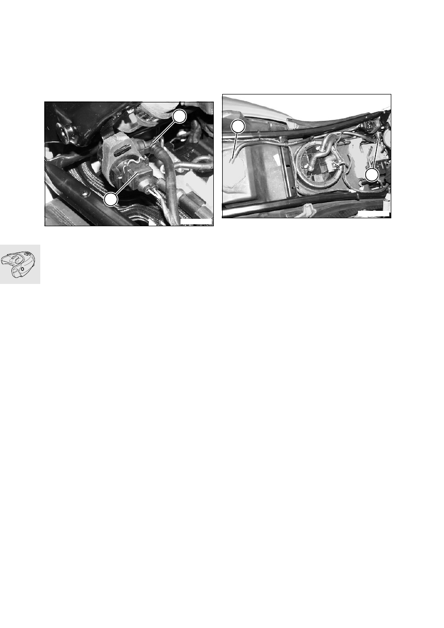
Disconnect plug (1) from fuel-evaporation con-
trol valve.

•

Disconnect the activated charcoal filter from fuel-
evaporation control valve (2).

•

Disconnect the breather hose from the throttle 
flap stub to the fuel-evaporation control valve.

•

Remove the fuel-evaporation control valve.

•

Installation is the reverse of the removal proce-
dure.

16 13 001 

Removing and installing 

activated charcoal filter

[USA version]
–

Place motorcycle on its centre stand.

–

Remove seat.

•

Disconnect the fuel hose from roll-over valve (3).

•

Disconnect the activated charcoal filter from fuel-
evaporation control valve (4).

–

Raise the rear frame.

a

.................................................... See Group 46

•

Remove the securing screw from the underside 
of the holder for the activated charcoal filter.

•

Pull the holder complete with the activated char-
coal filter down to remove.

•

Open the holder and remove the activated char-
coal filter.

•

Installation is the reverse of the removal proce-
dure.

X 

Tightening torques:

Rear frame to main frame ............................. 21 Nm
Brake fluid reservoir to rear frame .................. 5 Nm
Clamp for silencer ........................................ 55 Nm
Oxygen sensor to exhaust............................ 45 Nm
Exhaust manifold to cylinder head................ 20 Nm
Engine guard to frame.................................... 9 Nm

E160100

2

1

E160110

3

4

17.1

Contents

Page

17

Technical Data

............................................................................................................................... 3

Coolant circuit 

................................................................................................................................5

Thermostat, components 

.........................................................................................................6

Removing and installing coolant pump 

............................................................................7

Removing coolant pump

 ..............................................................................................................7

Installing coolant pump

 ................................................................................................................8

Adding coolant

 .................................................................................................................................8

Removing and installing coolant-temperature sensor

 ....................................................9

Checking cooling system for leaks 

..................................................................................10

Removing and installing coolant hoses 

.........................................................................10

Replacing coolant hose (radiator/water pump)

 ................................................................10

Replacing coolant hose (filler bowl/expansion tank)

 .....................................................10

Replacing coolant 

......................................................................................................................10

See Group 00 ....................................................................................................................................10

Removing and installing fan 

.................................................................................................10

Removing and installing radiator 

.......................................................................................11

Removing and installing thermostat 

................................................................................11

17 Radiator

17.2

17.3

17

Technical Data

F 650 GS

Cooling system

Cooling system capacity

Total capacity

l (Imp.pints/

US quarts) 1.3 (2.29/1.37)

Coolant circuit

l (Imp.pints/

US quarts) 1.20 (2.113/1.268)

Coolant expansion tank

l (Imp.pints/

US quarts) 0.10 (0.176/0.106)

Coolant

Use only nitrite-free long-term antifreeze and 
corrosion inhibitor.

Fan cut-in temperature

°C (°F) 102 (225)

Cut-in temperature for coolant warning 
light

°C (°F) 118 (245)

Pressure relief valve in end cover opens at

bar (psi) 1.5 

+0.2 

(21.34 

+2.85

)

Coolant mixing ratio

Water: 50%, antifreeze: 50%
Protection down to —25 °C (–13 °F)

Thermostat opening temperature

°C (°F) 85 (185)

Cooling system test pressure

bar (psi) 1.5 (21.34)

17.4

17.5

Coolant circuit

E170010

17.6

Thermostat, components

1 Coolant-temperature sensor
2 Thermostat housing
3 Thermostat
4 Cover
5 O-ring
6 Spring clip

E170020

3

4

2

5

6

1

17.7

11 51 025 

Removing and installing 

coolant pump

11 51 025 

Removing coolant pump

–

Remove seat.

–

Remove left cover.

a

....................................................See Group 46

–

Drain engine oil.

a

....................................................See Group 00

–

Place motorcycle on side stand.

–

Position a drip tray beneath the engine.

•

Remove drain plug (1) from water pump.

•

Hold a funnel below the drain and open the radi-
ator cap.

•

Drain off all the coolant.

–

Place motorcycle on its centre stand.

•

Remove the gear shift pedal.

–

Remove the starter motor.

a

....................................................See Group 12

•

Disconnect clutch cable at releaser shaft.

•

Disconnect the oil return line from the engine and 
the oil tank.

•

Disconnect the oil line from the cylinder head.

•

Using hose clip pliers, BMW No. 17 5 500, re-
move hose clips (13).

•

Remove water pump cover (2) with seal (3).

•

Drive out pin (5) and remove impeller (4).

•

Remove left engine cover (9).

•

Press out sealing rings (7, 8).

•

Remove shaft (6) by pulling inwards.

•

Remove washer (10), pin (11) and gear (12).

E170070

1

2

4

3

6

5

7

9

12

8

10

11

E170060

13


Content   ..  17  18  19  20   ..