BMW AG Motorcycle (F 650 GS). Manual - part 16


  Index      Manuals     BMW AG Motorcycle (F 650 GS). Repair Manual


Search            


Content   ..  14  15  16  17   ..


BMW AG Motorcycle (F 650 GS). Manual - part 16


12.8

12 11 060 

Removing/installing ignition 

trigger

Remove fasteners securing ignition trigger (2) in 
right cover.

Remove cable holder (1).

Remove the rubber grommet of ignition 
trigger (4) from the cover.

Remove ignition trigger (3).

Installation is the reverse of the removal proce-
dure: pay particular attention to the following.

Coat the rubber grommet of the ignition trigger 
with 3 Bond 1209 before inserting it into the cov-
er.

Tightening torque:

Ignition trigger in cover................................... 8 Nm

Removing/installing stator

Remove cable holder (5).

Remove fasteners securing stator (6).

Remove the rubber grommet of stator (7) from 
the cover.

Installation is the reverse of the removal proce-
dure: pay particular attention to the following.

Coat the rubber grommet of the stator with 
3 Bond 1209 before inserting it into the cover.

Clean the threads of the screws and coat with 
Loctite 243.

Tightening torque:

Stator to cover
(clean threads + Loctite 243)........................ 10 Nm
Cable holder to cover..................................... 8 Nm
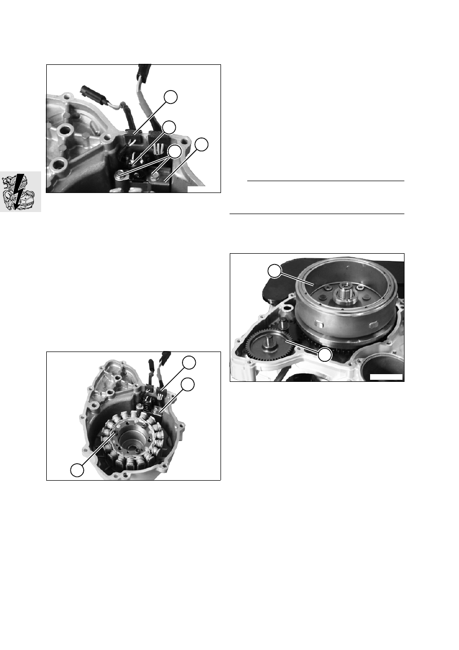
12 11 070 

Installing magnetic ignition 

trigger

12 11 070 

Installing magnet wheel

e

 Caution:

Tapers on crankshaft and magnet hub and hex nut 
must be clean and free of grease.

Apply a thin coat of Loctite 648 to the magnet 
hub taper.

Oil freewheel in freewheel housing.

Slide magnet wheel (8) onto crankshaft: woodruff 
key and keyway must be aligned.

Rotate starter double gear (9) counter-clockwise 
to enable the freewheel to slide on to the collar of 
the freewheel gear.

Clean the threads on the crankshaft and the 
threads of the nut.

Install snap ring and coat threads of hex nut with 
Loctite 243 and tighten.

E110380

2

1

3

4

E120060

6

5

7

E110370

9

8

12.9

Fit gasket.

Screw assembly handle,  BMW No. 12 5 500
into the central hole in the right engine cover.

Fit right engine housing cover and bolt together.

Remove assembly handle and screw in central 
plug.

Connect the plugs of the ignition trigger and the 
stator.

Clip the stator connector onto the plug.

Secure the cable cover to the engine.

Tightening torque:

Magnetic hub
(clean thread + Loctite 243)........................ 180 Nm
Engine cover, right ....................................... 10 Nm
Cable cover to engine .................................... 5 Nm

12 41 020 

Removing/installing or 

dismantling starter motor

12 41 020 

Removing/installing starter 

motor

e

 Caution:

Disconnect the negative battery cable first, then the 
positive cable.

Disconnect the battery.

Disconnect positive cable (1).

Remove fastener (2) from engine block and re-
move starter.

Installation is the reverse of the removal proce-
dure: pay particular attention to the following.

Check O-ring for damage and replace if neces-
sary.

e

 Caution:

Connect the positive battery cable first, then the 
negative cable.

Tightening torque:

Starter motor to engine block....................... 10 Nm
Positive cable to starter motor........................ 5 Nm

E120010

1

2

12.10

12 41 103 

Disassembling/assembling 

starter motor

Remove necked-down bolts (9).

Remove armature bearing cover (8) complete 
with brush-holder plate (6).

L

 Note:

Note thrust washers (2).

Remove fastener of positive contact (7), lift out 
brush holder and replace carbon brushes if nec-
essary.

Remove front cover (5).

Remove armature (3) from housing (1).

Using puller, BMW No. 00 8 400, pull the ball 
bearing (4) off the armature shaft.

L

 Note:

The insulation should be 0.5 mm (0.02 in) deeper 
than the commutator discs: if necessary, remachine 
with commutator saw.

Installation is the reverse of the removal proce-
dure: pay particular attention to the following.

Use a suitable tool such as a socket or similar to 
press the ball bearing onto the armature shaft.

Using protective jaws, clamp the armature in a 
vise and slide the brush-holder plate into posi-
tion, pushing the carbon brushes back for clear-
ance.

L

 Note:

Make sure that the mark on the housing (arrow) is 
aligned with positive contact point (10).

Tightening torque:

Necked-down bolts, starter housing .............. 5 Nm
Positive contact to starter motor .................... 4 Nm

E120020

3

4

5

9

6

1

2

7

8

E120070

10

12.11

12 12 011 

Replacing spark plug

See Group 00

12 12 085 

Replacing ignition lead

Remove left, right and centre covers.

Remove the battery.

Remove the intake air silencer together with the 
intake air pipe.

Remove the fastener for the intake air silencer 
from the oil tank.

Remove the fasteners for the intake air silencer 
from the retainer.

Remove the starter relay from the holder.

Slacken the fasteners for the lid of the electronic 
equipment box.

Remove the fasteners for the battery tray.

Disengage the clamp securing the breather hose 
and disconnect the hose from the intake air si-
lencer.

Press the oil tank slightly to the left and carefully 
disconnect the intake air silencer from the throt-
tle flap stub.

Pull the intake air silencer with intake air pipe and 
battery carrier to the rear to remove.

Cover/seal the throttle flap stub.

Disconnect the ignition lead from the ignition coil 
and the spark plug and remove.

Tightening torque:

Lid of electronic equipment box. .................... 4 Nm
Oil tank to intake air silencer .......................... 9 Nm
Intake air silencer to frame ............................. 9 Nm
Trim panel/cover ............................................ 3 Nm

12 13 000 

Removing/installing coil

Remove left, right and centre covers.

Remove the battery.

Remove the intake air silencer together with the 
intake air pipe.

Remove the fastener for the intake air silencer 
from the oil tank.

Remove the fasteners for the intake air silencer 
from the retainer.

Remove the starter relay from the holder.

Slacken the fasteners for the lid of the electronic 
equipment box.

Remove the fasteners for the battery tray.

Disengage the clamp securing the breather hose 
and disconnect the hose from the intake air si-
lencer.

Press the oil tank slightly to the left and carefully 
disconnect the intake air silencer from the throt-
tle flap stub.

Pull the intake air silencer with intake air pipe and 
battery carrier to the rear to remove.

Cover/seal the throttle flap stub.

Disengage cover (1) from the anchorages on 
main frame on each side and remove.

Disconnect starter coil (2) at plug.

Pull spark plug connector (4) off spark plug.

Remove screws securing ignition coil (3) to cylin-
der head cover.

Tightening torques:

Ignition coil to cylinder head........................... 9 Nm
Lid of electronic equipment box ..................... 4 Nm
Oil tank to intake air silencer .......................... 9 Nm
Intake air silencer to frame ............................. 9 Nm
Trim panel/cover ............................................ 3 Nm

E000030

1

2

3

4

12.12

13.1

Contents

Page

13

Technical Data

............................................................................................................................... 3

Removing and installing BMS control unit 

.....................................................................5

Removing and installing intake air pipe 

...........................................................................5

Removing/installing air temperature sensor

 .......................................................................5

Replacing air filter element 

....................................................................................................6

See Group 00 ......................................................................................................................................6

Removing and installing intake air silencer 

...................................................................6

Removing and installing intake air pipe

 ................................................................................6

Removing and installing injection nozzle 

.......................................................................7

Removing and installing throttle valve actuator 

.........................................................7

Replacing throttle-valve potentiometer 

...........................................................................8

Removing and installing throttle-valve stub pipe 

.......................................................8

Removing and installing intake pipe 

.................................................................................9

Checking fuel pressure

 .............................................................................................................9

Removing and installing fuel hoses 

.................................................................................10

Removing and installing feed and return lines

 .................................................................10

Removing and installing line to fuel injector

 ......................................................................10

Removing and installing throttle cable 

..........................................................................10

See Group 32 ....................................................................................................................................10

13 Fuel preparation and control

13.2

13.3

13

Technical Data

F 650 GS

Fuel grade

Super (premium), unleaded. 95 octane (RON)

Mixture preparation

Manifold injection

Fuel pressure

bar (psi) 3.5±0.2 (49.8±2.8)

Throttle stub pipe intl. dia.

mm (in) 46 (1.8)

Air filter

Paper filter

Intake stub pipe

mm (in) 43 (1.7)


Content   ..  14  15  16  17   ..