BMW AG Motorcycle (F 650 GS). Manual - part 15


  Index      Manuals     BMW AG Motorcycle (F 650 GS). Repair Manual


Search            


Content   ..  13  14  15  16   ..


BMW AG Motorcycle (F 650 GS). Manual - part 15


11.56

11 00 050 

Installing engine

Installation is the reverse of the removal proce-
dure: pay particular attention to the following.

Working from the right, manoeuvre the engine on 
the lifter into position below the motorcycle.

Raise the engine and tilt it to the rear.

Manoeuvre the bottom engine mount into posi-
tion.

Raise the engine and manoeuvre the fasteners at 
the cylinder head into position.

Install the bottom rear engine mount fastener.

Install the pivot pin of the swinging arm bearing.

Back off the adjusting screws for the cylinder 
head mounts until they are seated against the 
cylinder head on each side and the cylinder head 
itself is centered in the frame.

Tightening torque:

Water pump drain screw .............................. 10 Nm
Intake air silencer to frame ............................. 9 Nm
Engine guard to frame .................................... 9 Nm
Engine oil drain plug..................................... 40 Nm
Rear quick-release axle .............................. 100 Nm
Drive chain tensioning screws ...................... 10 Nm
Exhaust manifold to cylinder head................ 20 Nm
Silencer to exhaust manifold ........................ 55 Nm
Footrest plate to main frame, left/right .......... 30 Nm
Cable cover to engine .................................... 5 Nm
Voltage regulator to bracket ........................... 7 Nm
Chain drive sprocket to mainshaft
(clean threads + Loctite 243) ...................... 140 Nm
Sprocket cover to engine ............................... 2 Nm
Ground terminal to engine block .................... 8 Nm
Connecting cable, idle indicator ..................... 2 Nm
Engine shell to engine .................................. 41 Nm
Engine shell to bracing tube ......................... 21 Nm
Frame trussing to engine shell...................... 21 Nm
Frame trussing to main frame ....................... 21 Nm
Spring-strut adjusting knob bracket 
to frame.......................................................... 9 Nm
Radiator to main frame at top ......................... 9 Nm
Swinging-arm pivot .................................... 100 Nm
Frame to engine at rear ................................ 41 Nm
Gearshift pedal to engine ............................. 13 Nm
Brake pedal to frame .................................... 21 Nm
Cylinder head to frame ................................. 41 Nm
Cylinder head to frame adjusting sleeve

...............................................zero play max. 5 Nm

Cylinder head to frame locknut................... 100 Nm

e

 Caution:

Never start the engine after it has been dismantled 
and re-assembled until the engine oil circuit has 
been bled.

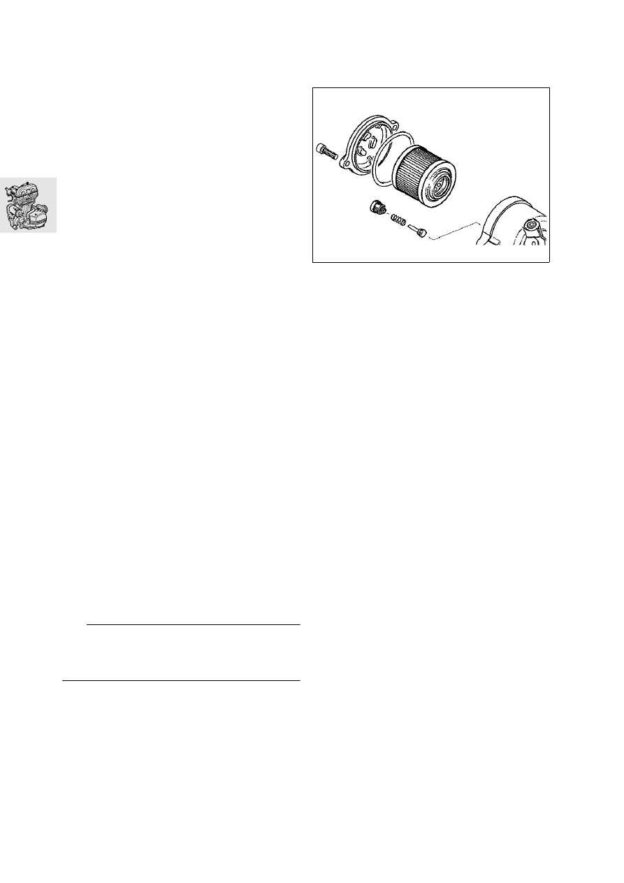
Bleeding engine oil circuit

Remove oil filter.

Remove pressure retaining valve (1).

Remove spark plug.

Turn engine over with the starter motor until oil 
emerges at the filter chamber.

Install pressure retaining valve.

Install oil filter.

Turn engine over with starter motor until oil 
emerges from the oil tank return line.

Switch on engine, run for a few minutes, then 
switch off.

Check oil and coolant levels and top up if neces-
sary.

Tightening torque:

Pressure retaining valve ............................... 24 Nm
Oil filter cover ............................................... 10 Nm

F110850

12.1

Contents

Page

12

Technical Data

............................................................................................................................... 3

Ignition magneto 

...........................................................................................................................5

Ignition magneto, components 

.............................................................................................6

Removing ignition magnet

 .......................................................................................................7

Removing right engine housing cover

 ...................................................................................7

Removing/installing ignition trigger

 .........................................................................................8

Removing/installing stator

 ...........................................................................................................8

Installing magnetic ignition trigger 

....................................................................................8

Installing magnet wheel

 ................................................................................................................8

Removing/installing or dismantling starter motor 

.....................................................9

Removing/installing starter motor

 ............................................................................................9

Disassembling/assembling starter motor

 ...........................................................................10

Replacing spark plug 

...............................................................................................................11

See Group 00 ....................................................................................................................................11

Replacing ignition lead 

...........................................................................................................11

Remove the intake air silencer together with the intake air pipe.  .......................................................11

Removing/installing coil 

.........................................................................................................11

Remove the intake air silencer together with the intake air pipe.  .......................................................11

12 Engine electrics

12.2

12.3

12

Technical Data

F 650 GS

Ignition system

Type

Fully transistorised ignition integrated in BMS.

Inductive sensor

190

-300

Ignition

Ignition system

BMS (mapped characteristic control)

Speed governing

rpm 7500

Ignition coil

Primary coil

m

500 ±50

Starter motor

Type

Permanent magnet motor with wedge-block free-
wheel, driving crankshaft via countershaft.

Power rating

kW 0.9

Ratio

1:32

Alternator

Type

Permanent excitation

Drive

Off crankshaft

Maximum output rating

W/V 400/14

Maximum current

A 29

Max. operating speed

rpm 7500

Spark plug

NGK

D8 EA

Thread

metric M 12 x 1.25

Electrode gap

mm (in) 0.6-0.7 (0.02-0.03)

12.4

12.5

Ignition magneto

E120050

12.6

Ignition magneto, components

1 Ignition trigger
2 Freewheel housing
3 Lock ring
4 Freewheel gear
5 Starter countershaft
6 Freewheel
7 Magnet rotor
8 Stator winding

E120040

8

7

6

4

2

3

1

5

12.7

12 11 070 

Removing ignition magnet

e

 Caution:

Never disconnect plug connection on ignition sys-
tem while engine is running.

11 14 859 

Removing right engine 

housing cover

Remove fasteners of cable cover (1).

Disconnect the plug of the stator (4) from 
connector (2).

Disconnect the plug of ignition trigger (3).

Remove retainer on right engine housing cover.

Remove central plug and install handle, 
BMW No. 12 5 500.

Remove the cover, noting the thrust 
washer (arrow).

Unscrew hex nut.

Heat hub to 80 °C (176 °F).

L

 Note:

Use temperature measuring device, 
BMW No. 00 1 900, to check the temperature.

Using puller, BMW No. 12 5 510, pull off magnet 
rotor.

E120030

3

2

4

1

E110180

12 5 500

E110190

E110210

12 5 510


Content   ..  13  14  15  16   ..