BMW AG Motorcycle (F 650 GS). Manual - part 6


  Index      Manuals     BMW AG Motorcycle (F 650 GS). Repair Manual


Search            


Content   ..  4  5  6  7   ..


BMW AG Motorcycle (F 650 GS). Manual - part 6


00.24

00 12 620 

Replacing spark plugs

(Inspection III)

Pull spark plug connector off spark plug.

Remove the spark plug with the a/f 18 socket 
wrench.

Installation is the reverse of the removal proce-
dure.

Tightening torques:

Spark plug.................................................... 20 Nm

Emptying drain hose from intake air 
silencer

(Inspections II and III)

Have a funnel and drip tray ready.

Remove the plug (arrow) and drain off all the oil.

e

 Caution:

Dispose of used oil in an environmentally compati-
ble manner.

00 13 630 

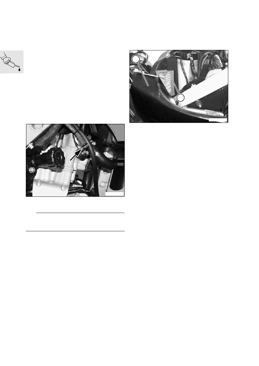
Replacing air cleaner 

element

(Inspection III)

Remove right cover.

Remove connecting flange from air filter box.

Pull intake air duct (1) out of the holder.

Remove air filter element (2).

Clean the intake air silencer.

Assembly is the reverse of the disassembly pro-
cedure.

Tightening torques:

Connecting flange .......................................... 5 Nm

E000130

E000140

1

2

00.25

00 16 617 

Replacing fuel filter

(Inspection III, every 20,000 km/12,000 miles)

d

 Warning:

Comply with safety precautions when handling or 
working with fuel; note that the fuel lines are 
pressurised.

Remove left cover.

Remove clips (2) and fastener (1) and pull the oil 
tank out of the holder.

Remove the BMS control unit from the holder.

Remove the fastener securing the fuel filter to 
frame (6).

Close off fuel supply line (7) and the line to the 
fuel injector (5) with hose clips, 
BMW No. 13 3 010.

Slacken the hose clamps.

d

 Warning:

Fuel escapes from the filter when the lines are dis-
connected.

Disconnect fuel lines (3, 5, 7) from the filter.

Remove clamp (4) from the fuel filter.

Installation is the reverse of the removal proce-
dure: pay particular attention to the following.

e

 Caution:

Note the installed positions of fuel feed line (7) and 
fuel return line (3).

Close hose clamps with pliers, 
BMW No. 13 1 500.

Tightening torques:

Fuel filter to frame .......................................... 9 Nm
Oil tank to intake air silencer .......................... 9 Nm
Air filter box to frame ...................................... 9 Nm
Connecting flange, air filter box
to battery tray................................................. 5 Nm

E000110

1

2

E130100

13 3 010

6

5

7

3

4

00.26

21 00 004 

Checking clutch play, 

adjusting if necessary

(Inspections I, II and III)

Release lever (1) on the gearbox must be located 
on the splines such that when it is pressed for-
ward as far as the release point, distance “A” is 
as specified.

Distance “A” .................  47...52 mm (1.85...2.05 in)

Adjust dimension “B” by turning adjusting 
screw (2) on the clutch handlebar lever.

Lock adjusting screw (2) with knurled nut (3).

Dimension “B” ............. 1.0...2.0 mm (0.04...0.08 in)

Checking wheel spoke tension, 
adjusting if necessary

(Inspection II)

Strike the spokes and listen for differences in the 
pitch of the sound.

If spokes are loose, tighten them with spoke nip-
ple wrench, BMW No. 36 3 800.

Vertical runout.......................... max. 2 mm (0.08 in)
Lateral runout........................... max. 2 mm (0.08 in)

E000240

A

1

E000200

B

3

2

00.27

Checking brake pads and discs for 
wear, replacing if necessary

(Inspections II and III)

Checking brake pads for wear

Brake pads, front brake

Visually inspect the brake pads.

The brake pad wear marks (arrows) must be 
clearly visible.

Brake pads, rear brake

Measuring brake pad thickness (arrows)

Minimum pad thickness ................. 1 mm (0.04 in)

Replacing brake pads

e

 Caution:

Do not operate the brake when dismantled.
Do not permit the brake pads to wear past the spec-
ified minimum thickness.
Always replace the brake pads as a complete set.

00 34 630 Brake pads, front brake

Press the brake calliper against the brake disc in 
order to force the pistons back.

Remove keeper (3).

Drive out retaining pin (2).

Remove the brake pads.

Remove fasteners (1) and remove brake calliper.

Make sure that spring (4) is correctly seated and 
installed right way round: engraved arrow must 
point in forward direction of travel.

Install the brake pads.

Install the keeper and the retaining pin.

Install brake calliper.

Operate brake several times until brake pads are 
correctly seated.

Tightening torques:

Brake calliper to fork slider tube................... 41 Nm

E000060

E000070

E340030

3

2

1

E340010

4

00.28

00 34 633 Brake pads, rear brake

Press the brake calliper against the brake disc in 
order to force the pistons back.

Remove keeper (1).

Drive out retaining pin (2).

Remove brake pads.

Installation is the reverse of the removal proce-
dure: pay particular attention to the following.

Operate brake several times until brake pads are 
correctly seated.

Checking the brake discs

Carefully check the brake discs for cracks, dam-
age, deformation and scoring.

Measure the thickness of the brake discs at sev-
eral points with a calliper gauge.

Brake disc wear limits
Front brake disc ...........................  4.5 mm (0.18 in)
Rear brake disc ............................  4.5 mm (0.18 in)

Checking the brake fluid level and 
topping up if necessary

(Inspection II)

L

 Note:

The volume of the brake fluid (MIN/MAX) is sufficient 
for lining thicknesses from new to the wear limit. It is 
not normally necessary to top up the fluid to accom-
modate lining wear.
A level below MIN indicates the possibility of other 
faults.

Brake fluid level (front brake)

Checking brake fluid level (front brake)

Turn the handlebars so that the cover of the res-
ervoir is horizontal.

The brake fluid must be between the top of the 
sight glass and the centre of the sight 
glass (arrow).

Topping up brake fluid level (front brake)

Release fasteners (3).

Remove cover complete with rubber gaiter.

Add brake fluid up to the top of the sight glass.

Installation is the reverse of the removal proce-
dure: pay particular attention to the following.

Wipe the rim of the reservoir, the rubber gaiter 
and the cover to remove brake fluid.

Brake fluid grade .........................................DOT 4

E340020

1

2

E000080

E000120

3

00.29

Brake fluid level (rear brake)

Checking brake fluid level (rear brake)

Maximum level ............................................ “MAX”
Minimum level ..............................................  “MIN”

Topping up brake fluid level (rear brake)

Take off cover (1) with rubber gaiter.

Top up the brake fluid level to the “MAX” 
mark (arrow).

Wipe the rim of the reservoir, the rubber gaiter 
and the cover to remove brake fluid.

Brake fluid grade .........................................DOT 4

Checking operation of brake system 
and freedom from leaks, repairing/
replacing if necessary

(Inspection III)

Check all brake lines for damage and correct 
routing.

Wipe down all threaded unions on the brake lines 
and check them.

Apply firm pressure to the brake lever and brake 
pedal and keep this pressure applied for a few 
moments. 

Release the brakes and check the brake lines for 
leaks.

d

 Warning:

Defective lines and threaded unions in the brake 
system must always be replaced without delay.

E0000090

1

00.30

00 34 606 

Changing brake fluid

(Inspection IV)

e

 Caution:

Refer to notes on the hazards involved in handling 
brake fluid.
Do not allow brake fluid to come into contact with 
painted parts of the motorcycle, because brake fluid 
destroys paint.

Changing brake fluid (front brake)

Turn the handlebars so that the cover of the res-
ervoir is horizontal.

Remove cover (1) complete with rubber gaiter 
and top up the level of brake fluid in the reservoir.

Connect the brake bleeding device to the bleed 
screw on the brake calliper.

Open the bleed screw by half a turn.

e

 Caution:

While bleeding the system, do not allow the brake 
fluid level to drop below the centre of the sight glass 
(arrow), as otherwise air will be drawn into the brake 
system. Bleed the system again if this happens.

Draw off brake fluid until it emerges clear and 
free from air bubbles. 

Tighten the bleed screw.

Installation is the reverse of the removal proce-
dure: pay particular attention to the following.

Before reassembling, carefully wipe the rim of 
the reservoir, the rubber gaiter and the cover to 
remove all traces of brake fluid.

Brake fluid grade .........................................DOT 4

Tightening torques:

Bleed screw ................................................... 7 Nm

Changing brake fluid (rear brake)

Remove cover (2) complete with rubber gaiter 
and top up the level of brake fluid in the reservoir.

Connect the brake bleeding device to the bleed 
screw on the brake calliper.

Open the bleed screw by half a turn.

e

 Caution:

Brake fluid level must not drop below the MIN mark 
during the bleeding process, otherwise air will be 
drawn into the brake system. Bleed the system 
again if this happens.

Draw off brake fluid until it emerges clear and 
free from air bubbles. 

Tighten the bleed screw.

Installation is the reverse of the removal proce-
dure: pay particular attention to the following.

Before reassembling, carefully wipe the rim of 
the reservoir, the rubber gaiter and the cover to 
remove all traces of brake fluid.

Brake fluid grade .........................................DOT 4

Tightening torques:

Bleed screw ................................................... 7 Nm

E000120

1

E0000090

2

00.31

Replacing primary sealing boot, 
front brake master cylinder

(Inspection III, every 40,000 km/24,000 miles for 
motorcycles with ABS)

Place the motorcycle on its main (centre) stand.

e

 Caution:

Do not allow brake fluid to come into contact with 
painted parts of the motorcycle, because brake fluid 
destroys paint.

Drain the front brake system.

Remove the hand-brake lever.

Remove thrust pin (2) with boot (1) and spring.

Carefully force back the brake piston.

Remove retaining ring (3).

Use pliers to remove brake piston (4).

Remove spring (6) with insert (5).

e

 Caution:

Note the washer between the brake piston and the 
boot.

Remove front boot (7).

Installation is the reverse of the removal proce-
dure: pay particular attention to the following.

e

 Caution:

Sealing lips of the boots toward the pressure cham-
ber.

Install new front boot.

Prior to installation, coat the brake piston and the 
boots with the assembly fluid supplied.

Lightly grease the thrust pin with 
Shell Retinax A.

Fill and bleed the brake system.

Tightening torques:

Pivot pin of handbrake lever ........................... 7 Nm
Locknut of handbrake lever ............................ 7 Nm

E340120

2

1

E340130

3

4

E340140

5

6

7


Content   ..  4  5  6  7   ..