BMW AG Motorcycle (F 650 GS). Manual - part 5


  Index      Manuals     BMW AG Motorcycle (F 650 GS). Repair Manual


Search            


Content   ..  3  4  5  6   ..


BMW AG Motorcycle (F 650 GS). Manual - part 5


00.16

00 13 624 

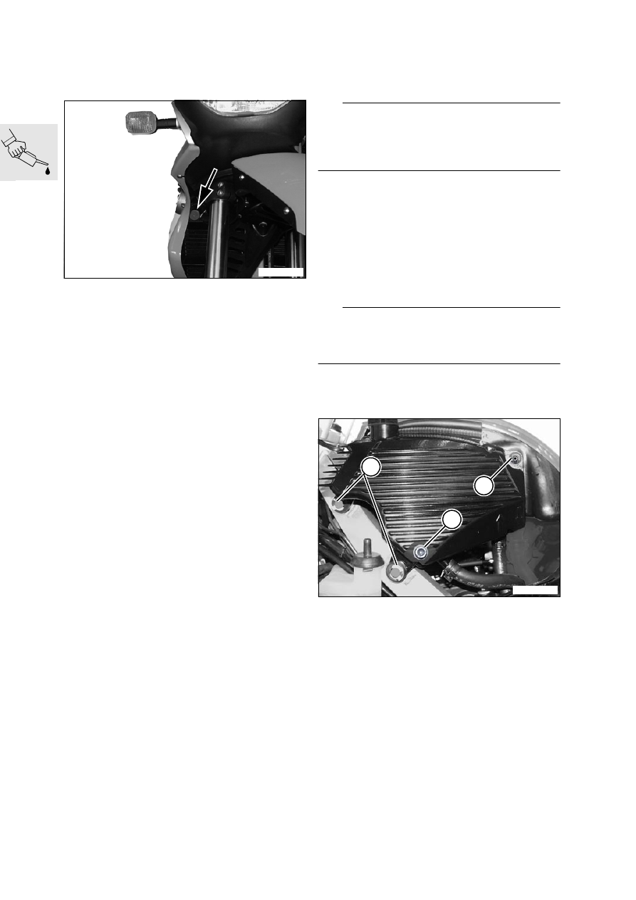
Reading the fault code 

memory with the MoDiTeC

(Inspections I, II, III and IV)

Unclip diagnosis plug (arrow) behind cover on 
right.

Connect the diagnosis unit to the diagnosis plug.

Read out the fault memory.

Carry out repairs as specified.

00 11 215 

Changing the engine oil and 

oil filter element

(Inspections I, II, III and IV)

L

 Note:

If an engine failure occurs, the oil tank and feed line 
must be cleaned with the material used for this pur-
pose in the workshop, and then blown through with 
compressed air.

00 11 215 

Preparatory work

Remove left cover.

a

.................................................... See Group 46

Remove engine guard.

Remove cover for chain sprocket from engine.

00 11 215 

Draining engine oil

d

 Warning:

Observe the hazard avoidance instructions for run-
ning internal combustion engines in enclosed spac-
es.

Warm up the engine to operating temperature.

Place a suitable container in position to catch the 
oil.

Slacken drain plug (2) in oil tank. 

Remove retaining screw (1).

Remove clamps (3).

Pull out the oil tank, tilt it to the left and slacken 
drain plug (2).

Use the spark-plug wrench (toolkit) to remove 
the filler cap from the oil tank.

Fully drain the tank.

Remove the oil drain plug from the engine and 
fully drain the oil from the engine.

E000050

E000110

2

1

2

3

00.17

00 11 215 

Replacing oil filter element

Remove the left-hand screw (3) securing the oil-
filter cover (1).

Remove the cable for the neutral indicating 
switch from its guide.

Engage the oil drain guide, BMW No. 11 7 511
on the pins (arrows) on the engine block.

Position a drip tray beneath the engine.

Remove the screws (2) and remove the oil-filter 
cover.

Remove the filter element.

Fully drain the oil and clean the oil-filter housing.

e

 Caution:

Dispose of the used oil and oil filter in an environ-
mentally compatible manner.

Fit a new filter element onto the oil-filter cover.

Coat the O-ring of the new filter element lightly 
with oil.

Check the O-ring of the oil-filter cover for dam-
age and replace if necessary.

Install the oil-filter cover complete with filter ele-
ment.

Installation is the reverse of the removal proce-
dure: pay particular attention to the following.

L

 Note:

Do not reinstall the engine guard, cover and chain 
sprocket cover at this stage, if other maintenance 
work has to be performed on assemblies normally 
concealed by these components.

Tightening torques:

Oil filter cover ............................................... 10 Nm
Cover for chain sprocket ................................ 2 Nm

00 11 215 

Filling with engine oil

Install the oil drain plug in the oil tank with a new 
sealing ring and tighten.

Install the oil drain plug in the engine with a new 
sealing ring and tighten.

Fill the oil tank with 2 l (3.5 Imp. pints/2.1 US 
quarts) of engine oil and install the filler cap.

d

 Warning:

Observe the hazard avoidance instructions for run-
ning internal combustion engines in enclosed spac-
es.

Run the engine for thirty seconds.

Add another 0.3 l


(0.53 Imp. pints/0.32 US 

quarts) of engine oil to the oil tank.

Installation is the reverse of the removal proce-
dure: pay particular attention to the following.

e

 Caution:

Make sure that when the engine is at operating tem-
perature, the oil level is not above the specified 
level (arrow).

Check the oil level with the engine at operating 
temperature and top up if necessary.

Operating fluids:
Brand-name HD oil, API classification SF, SG or SH; 
suffix letters CD or CE are permitted; alternatively, 
brand-name HD oil of CCMC classification G4 or 
G5; suffix PD2 is permitted.

Engine oil capacity:
For filter 
change.......... 2.3 l (4.05 Imp. pints/2.43 US quarts)

Tightening torques:

Oil tank drain plug ........................................ 21 Nm
Engine oil drain plug..................................... 40 Nm
Engine guard to frame.................................... 9 Nm

E000190

3

2

1

11 7 511

E000010

00.18

Checking coolant, topping up if nec-
essary

(Inspections I, II and III)

L

 Note:

Check coolant level only when the engine is cold.
Do not refill the coolant expansion tank if valve clear-
ance still has to be checked/adjusted.

Checking coolant

Check coolant level through the sight glass in the 
left cover.

Top up the coolant if the level is below the MIN 
mark.

Adding coolant

Remove left cover.

a

....................................................See Group 46

e

 Caution:

Anti-freeze protection must be guaranteed to at 
least -30 °C (-22 °F). Use only nitrite-free long-term 
antifreeze and corrosion inhibitor.
Do not top up expansion tank past the MAX 
mark (A).

Check antifreeze concentration in the expansion 
tank, top up antifreeze if necessary.

L


Note:

Mix the coolant in a mix ratio of 50 % antifreeze, 
50 % water.

Check coolant level in the expansion tank, top up 
coolant if necessary.

Maximum level........................................................ A
Minimum level......................................................... B

Installation is the reverse of the removal proce-
dure.

17 00 035 

Changing coolant

(Inspection IV, every 2 years)

Remove left cover.

a

.................................................... See Group 46

Place motorcycle on side stand.

Position a drip tray beneath the engine.

Remove drain plug (1) from water pump.

Hold a funnel below the drain and open the radi-
ator cap.

Drain off all the coolant.

E000020

A

B

E000210

1

00.19

Disconnect the coolant hose (arrow) at the frame 
on the left and drain the radiator.

Remove fastener (1), lift out the expansion tank 
and drain off all coolant.

e

 Caution:

Dispose of old coolant in an environmentally com-
patible manner.

L

 Note:

Do not install and refill the coolant expansion tank if 
valve clearance still has to be checked.

Install the expansion tank.

Install the drain plug with a new sealing ring and 
tighten.

Place motorcycle on its centre stand.

Slacken bleed screw (2) in cylinder head.

Connect a hose to the bleed screw.

Fill the radiator until coolant escapes at the bleed 
screw; repeatedly squeeze the coolant hoses to 
expel the air.

Tighten bleed screw (2).

Top up coolant until the level reaches the top of 
the filler neck (arrow).

Top up expansion tank to the MAX mark.

Capacity
Cooling 
system .......... 1.2 l (2.11 Imp. pints/1.27 US quarts)
In expansion 
tank............ + 0.1 l (1.17 Imp. pints/0.11 US quarts)

Antifreeze
Use only nitrite-free long-term antifreeze and corro-
sion inhibitor.

Concentration
Antifreeze .........................................................50%
Water ...............................................................50%

Run the engine for a short time, then switch it off.

Check coolant level and top up if necessary.

Installation is the reverse of the removal proce-
dure: pay particular attention to the following.

L

 Note:

Do not reinstall the cover at this stage, if other main-
tenance work has to be performed.

Tightening torques:

Drain plug .................................................... 10 Nm
Expansion tank to radiator ............................. 9 Nm
Bleed screw ................................................. 12 Nm

E170030

E000020

1

E170090

2

00.20

00 11 279 

Changing oil in telescopic 

forks

(Inspection III)

Place motorcycle on its centre stand.

Lift front wheel clear of the ground.

Remove the sealing caps from the fork legs.

Slacken clamp screws (1, 2) at top/bottom fork 
bridges.

Pull the fork legs up and tighten the clamp 
screws.

d

 Warning:

Note that plugs (4) at left and right are spring-load-
ed. Wear protective goggles when removing and in-
stalling.

Press plug (4) down and remove snap ring (3). 
Carefully allow the plug to ride up and remove.

Position a drip tray beneath the telescopic forks.

Slacken oil drain plugs (5) on left and right.

Allow all the oil to drain off.

e

 Caution:

Dispose of used oil in an environmentally compati-
ble manner.

Install the oil drain plugs (5) with new sealing 
rings and tighten.

Fill with specified quantity of oil.

Install plugs in left and right forks, complete with 
snap rings.

Slacken clamp screws (1, 2) at top/bottom fork 
bridges and lower the fork legs.

Tighten clamp screws at top and bottom fork 
bridges.

Install the sealing caps.

Oil content of each fixed fork tube

................... 0.60 l (1.06 Imp. pints/0.62 US quarts)

Operating fluids:
Telescopic fork................... BMW telescopic fork oil

Tightening torques:

Oil drain plug.................................................. 6 Nm
Clamp screws, 
top/bottom fork bridges ............................... 21 Nm

E310030

1

2

E310010

4

3

E310020

5

00.21

00 11 602 

Checking and adjusting 

valve clearances

(Inspections I, II and III)

00 11 601 

Checking valve clearances

Preparatory work

Remove left, right and centre covers.

Remove the battery.

Removing the intake air silencer together with 
the intake air pipe

Remove the fastener for the intake air silencer 
from the oil tank.

Remove the fasteners for the intake air silencer 
from the retainer.

Remove the starter relay from the holder.

Slacken the fasteners for the lid of the electronic 
equipment box.

Remove the fasteners for the battery tray.

Disengage the clamp securing the breather hose 
and disconnect the hose from the intake air si-
lencer.

Press the oil tank slightly to the left and carefully 
disconnect the intake air silencer from the throt-
tle flap stub.

Pull the intake air silencer with intake air pipe and 
battery carrier to the rear to remove.

Cover/seal the throttle flap stub.

Exposing the radiator

L

 Note:

When temporarily securing the expansion tank, 
make sure that the cap is above the level of the cool-
ant.

Disconnect the expansion tank from the radiator, 
pull it to one side and temporarily secure it to the 
handlebar with a cable tie or similar.

Unclip the MoDiTeC plug from its holder.

Disconnect plug for fan.

Disengage the clips at top and bottom and re-
move the fan.

Protect the interior of the radiator with cardboard 
or similar.

Exposing cylinder head

Disconnect ignition coil at plug (2).

Pull spark plug connector off spark plug.

Remove screws securing ignition coil (1) to cylin-
der head cover.

Disengage throttle cable from adapter (arrow).

Remove circlip (6) from throttle-cable holder and 
disengage throttle cable.

Disengage cover (4) from the anchorages on 
main frame on each side and remove.

Remove spark plug.

Use pliers, BMW No. 17 5 500, to release hose 
clip (5) and disconnect cylinder-head breather 
hose (7).

L

 Note:

Note the position of the two anchorages for ignition 
coil (1) on the cylinder-head cover.

Remove 8 fasteners (3) and remove the cylinder-
head cover with gasket.

Turning crankshaft to TDC position

Remove the central threaded plug in the magnet-
ic housing.

Use an Allen key to turn the crankshaft clockwise 
to the TDC position.

E000150

E000030

1

2

3

5

6

4

7

00.22

Checking valve clearance

Use a feeler gauge (arrow) to determine valve 
clearance.

Make a note of the valve clearances, or adjust 
them if necessary.

Valve clearances:
Inlet valve ............... 0.05...0.10 m (0.002...0.004 in)
Exhaust valve ...... 0.25...0.30 mm (0.010...0.012 in)

00 11 602 

Adjusting valve clearances

Secure yoke of valve-clearance adjuster, 
BMW No. 11 7 501, to the cylinder head.

Seal the aperture in the cylinder head with the 
cover plate (arrow).

Turn the camshaft until the points of the cams 
are up.

L

 Note:

Thruster toward outer edge of cylinder head.

Install shaft, BMW No. 11 7 502, thruster, 
BMW No. 11 7 503, and clamp block, 
BMW No. 11 7 504.

Turn the bucket tappet until the shim (arrow) can 
be levered out at the groove in the bucket tappet.

Secure thruster, BMW No. 11 7 503, on the 
shaft by tightening the screw (arrow).

Position thruster, BMW No. 11 7 503, on the 
edge of the bucket tappet.

Press down the bucket tappet and secure shaft, 
BMW No. 11 7 502, with clamp block, 
BMW No. 11 7 504.

L

 Note:

If the shim is too tight to be removed easily, the 
hold-down assembly is sitting on the shim instead of 
on the edge of the bucket tappet. If this happens 
back off the hold-down assembly and repeat the 
procedure.

Release the shim with a screwdriver or similar 
tool, then use magnetic holder, 
BMW No. 11 7 505, to remove. 

E000160

11 7 504

11 7 502

11 7 503

E000170

11 7 501

E000170

E000040

11 7 503

00.23

Before installing new shim, check thickness with 
a micrometer.

Position the shim in the bucket tappet.

Carefully release the clamp on the shaft, then re-
move the shaft and the hold-down assembly.

e

 Caution:

Check that the shim is correctly seated in the bucket 
tappet.

Installation is the reverse of the removal proce-
dure: pay particular attention to the following.

Installing cylinder head cover

Before installing the cylinder head cover, remove 
all traces of the gasket and clean the sealing face 
with degreasing agent. Also clean the groove 
and the seating faces for the gasket.

Installing fan shroud

Engage the tabs at the top and bottom of fan 
shroud (2) in the hooks on the radiator (1).

Installing intake air silencer

L

 Note:

Do not reinstall the intake air silencer at this stage, if 
the fuel filter has to be removed.
Make sure that the intake pipe is correctly seated on 
the throttle flap stub.

Installing the intake air duct

Introduce the fits of intake air silencer (5) with air 
filter element (6) and intake air duct (4) into the 
guide on the battery tray (3)/connecting flange.

If necessary, top up the coolant level in the ex-
pansion tank.

Valve clearances:
Inlet valve ............... 0.05...0.10 m (0.002...0.004 in)
Exhaust valve ...... 0.25...0.30 mm (0.010...0.012 in)

Tightening torques:

Cylinder head cover to cylinder head ........... 10 Nm
Ignition coil to cylinder head........................... 9 Nm
Lid of electronic equipment box ..................... 4 Nm
Spark plug in cylinder head .......................... 20 Nm
Oil tank to intake air silencer .......................... 9 Nm
Intake air silencer to frame ............................. 9 Nm
Connecting flange, air filter box
to battery tray................................................. 5 Nm
Expansion tank to radiator ............................. 9 Nm
Trim panel/cover ............................................ 3 Nm

E000180

1

2

E130090

5

6

4

3


Content   ..  3  4  5  6   ..