Motorcycle BMW R1150RT. Manual - part 62
 

  Index      motorcycles     Motorcycle BMW R1150RT - service repair manual 2001 year


Search            


Content   ..  60  61  62  63   ..


Motorcycle BMW R1150RT. Manual - part 62


33.15

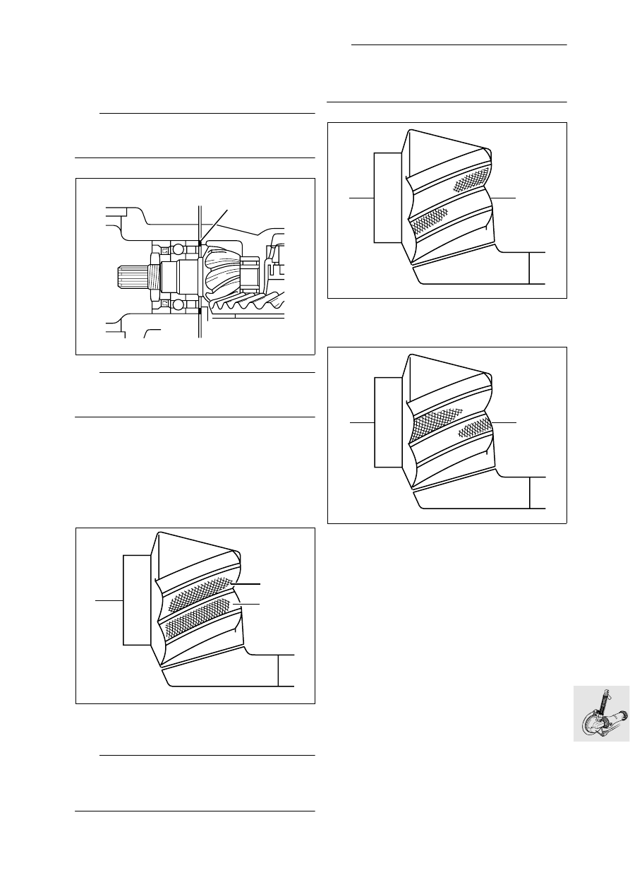
Checking tooth contact pattern

•

The contact pattern must be checked whenever 
the gearset, the housing or the drive pinion bear-
ing is replaced.

L

 Note:

Before checking the contact pattern, make sure that 
tooth backlash (provisional, if necessary) is correct.

L

 Note:

The contact pattern is adjusted at the shim 
washer (1) on the input bevel pinion.

•

Clean and degrease tooth flanks of crown wheel 
and bevel gear.

•

Coat three tooth flanks of the crown wheel with 
marking ink.

•

Install measuring fixture, BMW No. 33 2 600, 
centre crown wheel and use the balls of your 
hands to press it into the housing and turn it back 
and forth a few times.

•

If the correct shim is installed, the following con-
tact pattern appears with no load applied.

L

 Note:

The contact point is central on front flank “V”.
The contact pattern is closer to the larger diameter 
on trailing flank “R”.

e


Attention:

Teeth should never make contact at the smaller di-
ameter.

•

This contact pattern indicates that a thinner 
spacer shim should be installed.

•

This contact pattern indicates that a thicker 
spacer shim should be installed.

•

Clean the tooth flanks.

KR330250

1

KR330260

R

V

KR330270

KR330280

33.16

33 12 

Checking and adjusting backlash

•

Secure measuring device, BMW No. 33 2 600, 
with dial gauge to crown wheel and secure to 
housing with the knurled screw.

•

Secure measuring arm, BMW No. 33 2 603, 
centrally to crown wheel.

•

Using the balls of your hands, press the crown 
wheel into the housing and turn it to and fro to 
check tooth backlash.

L

 Note:

Check tooth backlash at three points 120 degrees 
apart; turn the bevel pinion with the crown wheel.

•

Compensate for excessive backlash by inserting 
a thinner shim washer, and for insufficient back-
lash by inserting a thicker shim washer (1).

L

 Note:

Install spacer with bevel on inside diameter toward 
crown wheel.

Backlash:
(Oil-free adjustment)

....................... 0.07...0.16 mm (0.0028...0.0063 in)

Preliminary tooth backlash

........................... 0.1...0.5 mm (0.0039...0.0197 in)

33 2 603

R21330130

33 2 600

90

°

S3300120

S3300100

1

33.17

Shimming housing cover

•

In order to obtain the correct taper roller bearing 
preload, the housing cover must be correctly 
shimmed. 

•

Using depth gauge, BMW No. 00 2 550, meas-
ure distance “a”.

•

Place measuring ring, BMW No. 33 2 601, in po-
sition and secure it.

•

Measure the distance from the ball bearing’s out-
er race through the window in the measurement 
disc to the housing flange surface to determine 
dimension “b”.

•

Distance “a” – distance “b” = shim thickness 
(without preload).

•

Apply a light coat of grease to the selected shim 
washer, and install it.

Preload:............ 0.05...0.1 mm (0.0020...0.0039 in) 

33 11 032 

Installing housing cover

•

Lightly oil the lip and outer edge of the sealing 
ring.

•

Using drift, BMW No. 33 1 860, and handle, 
BMW No. 00 5 500, drive in the sealing ring.

•

Heat housing cover to 80 °C (176 °F) and install. 

•

Tighten securing screws in diagonally opposite 
sequence.

X 

Tightening torque:

Housing cover .............................................. 35 Nm

33 12 

Installing splined element

•

Push the flexible gaiter on to the housing and se-
cure it with the clamping strap.

•

Coat splines on input pinion with 
Staburags NBU 30 PTM.

•

Fit sliding element to drive pinion.

•

Seat the retaining ring by tapping it gently (plastic 
hammer).

a

KR330290

00 2 550

33 2 601

S330130

S330140

33 1 860

00 5 500

33.18

33 10 050 

Installing rear-wheel drive unit

L

 Note:

Do not lay oil-filled rear-wheel drive on its side prior 
to installation, as this will cause oil to escape when 
the motorcycle is on the road (suction effect).

•

Coat splines of sliding element (arrow) with 
Staburags NBU 30 PTM.

•

Install the inner races of the needle roller bear-
ings with a small quantity of 
Staburags NBU 30 PTM.

•

Place rear-wheel drive with flexible gaiter in posi-
tion and introduce sliding element into universal 
shaft.

•

Install fixed-bearing stud bolt (1) with Loctite.

e

 Attention:

Make sure that the inner race never presses against 
the ends of the needles.

L

 Note:

Use an acetone-based cleaning agent such as
Loctite quick cleaner 706
Loctite Order No. 70636-AC

•

Screw in floating bearing stud (2) with Loctite.

e

 Attention:

When tightening threaded fasteners coated with 
Loctite 2701, always apply final torque without de-
lay.
Allow at least 3 hours for the Loctite to cure.

•

Tighten fixed bearing stud (1).

•

Tighten floating bearing stud (2).

•

Tighten locknut (3).

•

Tighten clamping strap (4) on gaiter.

•

Engage strut (5).

•

If necessary, fill with oil.

•

Install the rear wheel.

R22330010

2

1

3

4

5

6


Content   ..  60  61  62  63   ..