Motorcycle BMW R1150RT. Manual - part 60
 

  Index      motorcycles     Motorcycle BMW R1150RT - service repair manual 2001 year


Search            


Content   ..  58  59  60  61   ..


Motorcycle BMW R1150RT. Manual - part 60


33.7

33 12 

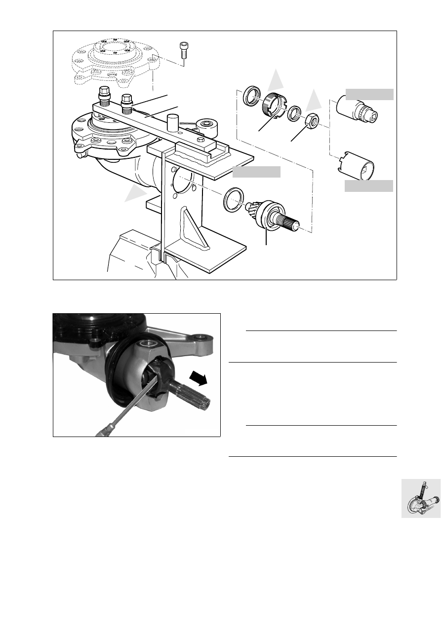
Removing input bevel pinion

•

Press out splined section of shaft.

•

If necessary, remove/install circlip.

•

Remove retaining strap and pull off the flexible 
gaiter.

•

Bolt the final-drive unit to the assembly stand, 
BMW No. 33 1 510/511.

•

Bolt the locking arm (1) to the retaining fixture.

•

Tighten grub screws until they are seated.

e

 Attention:

The grub screws must not project, or the neck of the 
housing could be damaged.

•

Screw home threaded sleeves (2) in rear wheel 
drive unit, then tighten with wheel studs.

•

Heat hex nut (3) on the input bevel gear 
to 100 °C (212 °F), and unscrew with 36 mm 
socket wrench insert and reducing adapter, 
BMW No. 33 1 720.

L

 Note:

If necessary, use cross-handle with two tubular ex-
tensions.

•

Heat the housing to max. 120 °C (248 °F) and re-
move threaded ring (4) with pin wrench, 
BMW No. 33 1 700.

•

To remove input bevel pinion (5), remove the 
crown wheel (

a

33.12).

S330020

h

100

h

120

S330030

33 1 700

33 1 720

2

1

5

h

120

4

3

w

w

w

33 1 510

33.8

•

Position rear wheel drive upright with retaining 
fixture, BMW No. 33 1 510.

e

 Attention:

To prevent the input bevel pinion from being dam-
aged when it falls out, use a soft underlay.

•

Heat the housing until the input bevel pinion is 
released (max. 120 °C/248 °C) and drops out.

•

Remove the input bevel pinion and the spacer.

33 12 

Disassembling input bevel pinion

•

Remove outer bearing race (1).

•

Clamp input bevel pinion (2) into vise with protec-
tive jaws (splines facing upwards).

•

Using puller, BMW No. 00 7 500, pull off both 
bearings at the same time.

•

Remove thrust ring (3).

•

Remove ball thrust bearing (4), inner race (5), roll-
er bearing cage (6) and outer race (7).

R21330010

w

h

120

33 1 510

R21330090

5

7

6

4

1

2

3

KR330100

00 7 500

33.9

33 12 Removing needle roller bearing for input 
bevel pinion

•

Heat the housing to 120 °C (248 °F).

•

Remove the outer ring of the needle roller bear-
ing using 
internal puller, BMW No. 00 8 573, threaded ex-
tension, BMW No. 00 8 575, and counter-sup-
port, BMW No. 00 8 572.

33 12 Installing needle roller bearing for input 
bevel pinion

•

Heat the needle roller bearing seat to 100 °C 
(212 °F).

•

Press in needle roller bearing using drift or the in-
put bevel pinion.

33 12 

Assembling input bevel pinion

•

Clean the threads of the input bevel pinion.

•

Heat the inner race (1) to 100 °C (212 °F) and 
push onto input bevel pinion (2) as far as the 
stop.

•

Push the outer race (3) together with the roller 
cage (4) on to the inner race.

•

Heat ball thrust bearing (5) to 100 °C (212 °F) and 
push fully on to input bevel pinion.

•

Allow input bevel pinion to cool down.

S330050

00 8 572

00 8 573

00 8 575

KR330131

1

2

3

4

5

h

100

w

w

h

100

33.10

33 12 

Installing input bevel pinion

•

Clean threads in the housing.

•

Clamp holder, BMW No. 33 1 510, in the vise in 
such a way that the input neck of the housing is 
pointing vertically upward.

•

Heat the neck of the housing to 
max. 120 °C (248 °F).

L

 Note:

Chill input bevel pinion prior to installation in refrig-
erator/freezer or similar, or use cooling spray.

•

Install spacer (2).

•

Install input bevel pinion (1) from above.

•

Clamp on the retainer, BMW No. 33 1 510, with 
the drive-side housing extension toward the 
front.

•

To secure the input bevel pinion, install the 
crown gear with housing cover.

•

Secure locking arm (8) to holder, 
BMW No. 33 1 510.

•

Insert outer race (3).

S330060

6

3

4

5

7

33 1 700

33 1 720

2

1

33 1 510

8

R21330070

1
2

33 1 510

w

j

120


Content   ..  58  59  60  61   ..