Motorcycle BMW R1150RT. Manual - part 54
31.12
31 42 405
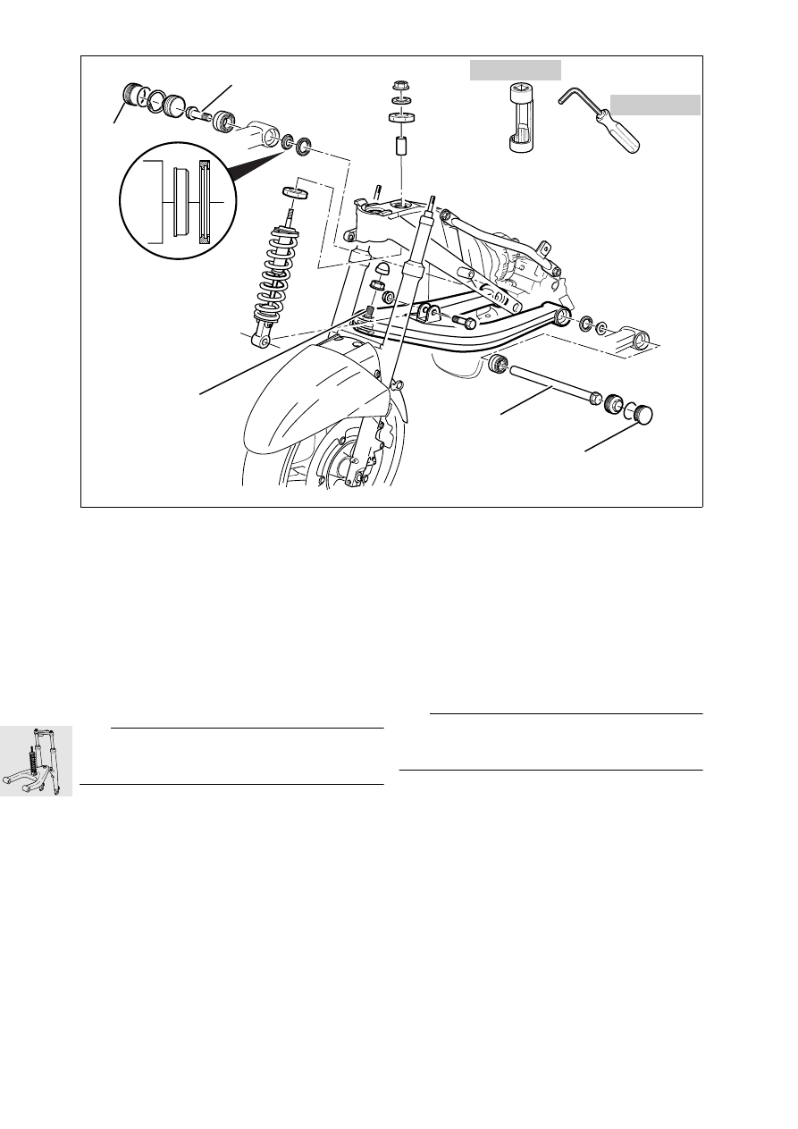
Removing and installing
leading link
•
Remove side panels (
•
Remove the intake air pipe.
•
Disengage suspension strut at bottom.
•
Heat ball joint mount (1) at leading link to
max. 120 °C (248 °F) and remove it.
•
Remove caps (2).
•
Slacken and turn flange of the left throttle valve
stub.
•
Remove screw (3).
•
Slacken fasteners of leading link pivot shaft (4).
e
Attention:
Protect parts against scratching; mask off if neces-
sary.
•
Pull telescopic fork forwards and carefully re-
move leading link by pulling forwards.
•
Installation is the reverse of the removal proce-
dure.
•
Apply a light coating of grease to the shaft before
installing.
•
Tighten the ball joint in the leading link using
socket, BMW No. 31 5 601, and Allen key,
BMW No. 31 5 603.
X
Tightening torque:
Leading link to ball joint
(clean thread + Loctite 2701)...................... 130 Nm
Leading link to engine:
right ............................................................. 73 Nm
Screw cap, left
(lightly coat threads with Optimoly TA).......... 42 Nm
Spring strut to leading link............................ 50 Nm
31 42
Disassembling and assembling
leading link
e
Attention:
Always install bearing by applying pressure to outer
race.
•
Press the bearing out/in with a suitable tool.
R22310070
4
2
31 5 603
31 5 601
1
2
3